

Page 1
Operating instructions for emergency stop switch ES-FB1W-XW
62
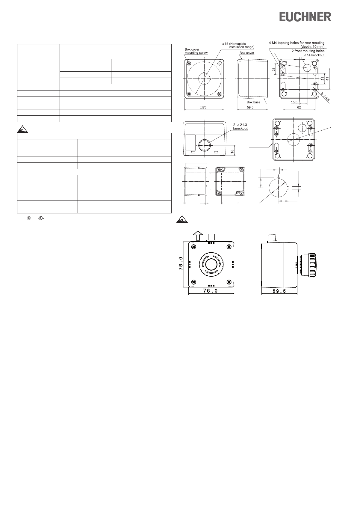
41
21
2-φ4.6
4 M4 tapping holes for rear mouting (depth: 10 mm)
2 front mouting holes
SAFETY NOTE
Turn off the power to the control unit before starting installation, removal,
wiring, and maintenance. Failure to turn power off may cause electric shocks
or fire hazard.
Use wires of a proper size to meet voltage and current requirements. Tighten
the terminal screws to recommended tightening torque. Improper wires and
loose terminals during operation will cause overheating and fire hazard.
Provide a proper protection against electric shocks.
Failure to turn power off may cause electric shock or fire hazard.
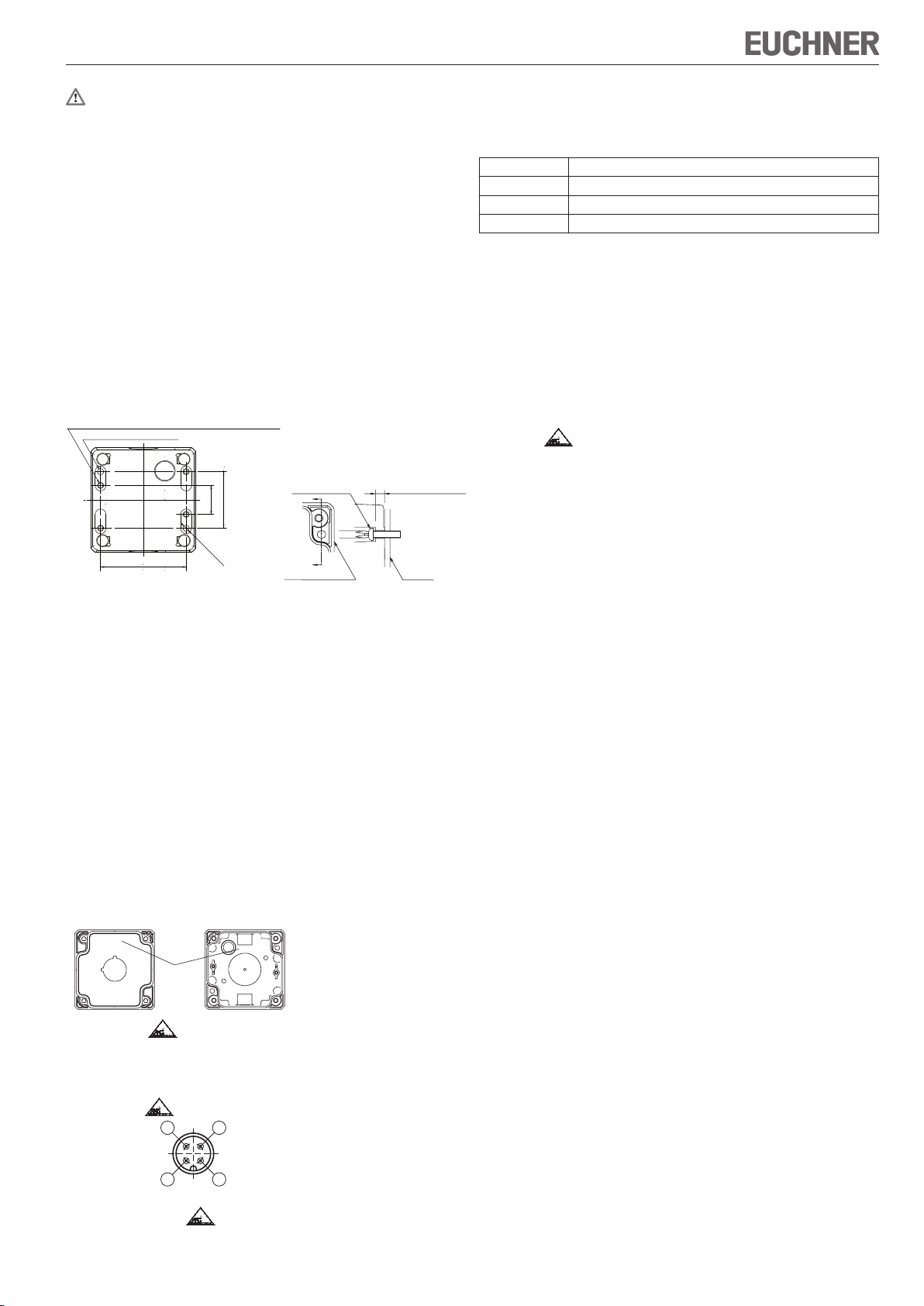
Mounting
Panel Mounting
1. Installing the FB series control box from the front
Use two M4 screws. (Recommended tightening torque: 1.4 to 2.0 Nm)
Determine the screw length in consideration of the box base and panel
thickness.
The cable is connected to the emergency stop switch on the box cover side with
a removable connector. To separate the box base and box cover completely,
remove the connector. This connector is equipped with a lock to prevent disconnection. Pull the connector while pressing the locking knob.
Screw (M4)
Box base Panel
2. Installing the FB series control box from the back
When installing from the back, insert M4 tapping screws into holes for the
tapping screws on the back of the box base (depth: 8 to 10 mm, tapping screw
hole diameter: Ø3.7 mm) [Recommended tightening torque: 1.3±0.1Nm.
3. Installation using accessories (FB9Z-PK1)
When using accessories for installation, refer to each instruction sheet.
Installing and removing the control unit
Refer to installation instructions for each control unit.
Installing a cable gland
Break a desired knockout to mount a cable gland using a hammer and a
screwdriver, and install the cable gland. When breaking the knockout to open
a cable gland hole, be careful not to damage the internal contact block.
Note that cracks or burrs on the cable gland hole will degrade the waterproof
characteristics.
Installing the box cover and box base
Attach the box cover to the box base so that the TOP mark on the box cover
and box base are in the same direction.
Use box cover mounting screws to attach the box cover to the box base.
(Recommended tightening torque: 1.3±0.1 Nm)
Make sure that the box cover and the box base are attached in the correct
direction. Otherwise, the ES-FB series control box may be damaged.
TOP
TOP
5.0 (Box base
thickness)
Applicable Wire
Determine the wire size in consideration of the control unit and cable thickness
of the cable gland.
When using plastic cable gland and multi-core cable
Gland port size Plastic cable gland
M20 5311 1220 (Skintop-ST-M), Applicable gasketGPM20 (LAPP, Germany)
G1/2 5380 6030 (Skintop-ST-PF), Applicable gasketGP 050 (LAPP, Germany)
PG13.5 5301 5030 (Skintop-ST), Applicable gasketGP13.5 (LAPP, Germany)
Locking nut for installing cable gland
(The locking nut for installing cable gland is not supplied. Order separately.)
Only UL approved cable glands are described.
When using the ES-FB control box in North America, be sure to use UL approved
plastic cable glands.
Tighten cable glands to a torque of 3.0±0.3Nm.
Insufficient tightening of the cable gland may degrade the waterproof characteristics.
Electric shock protection Class II is maintained only when a plastic cable gland is
used.
Determine the cable gland for a multi-core cable according to the outside diameter
of the cable sheath.
When wiring from the back of ES-FB series control box, use the Ø14 knockout on the
back of the control box. A cable gland cannot be installed to the Ø14 knockout.
Function
ES-XN/XW series emergency stop switches feature a slave connection to the
safety bus AS-Interface Safety at Work.The position monitoring of the safety
guard is carried out with two positively driven contacts.
When the button is in normal position it transmits a switch-specific, unique
safety code sequence with 8x4 bits via the AS-Interface. This code sequence
is evaluated by an AS-Interface safety monitor. The first positively driven NC
contact is represented by the AS-Interface input bits D0 and D1, while the
second positively driven NC contact is represented by D2 and D3.
The switch-specific safety code sequence is transmitted via the AS-Interface
input bits D0 to D3 when the safety guard is closed.
When the button is pushed, the values 0, 0, 0, 0 are transmitted in every bus
cycle by D0 to D3. The emergency stop switch must be configured correspondingly in the AS-Interface safety monitor (refer to the operating instructions of
the AS-Interface safety monitor used).
Notes for Operation
Wiring
Avoid foreign objects such as dust, liquid, and oil from entering the switch
while wiring.
Do not twist or pull the cable or cable gland with excessive force.
Otherwise, the wire, ES-FB series control box, and control units may be
damaged.
Because the ES-FB series control box is not provided with a PG
terminal, a bonding circuit cannot be interconnected.
Operation
Avoid any contact with oil or coolants. Otherwise, the control box may
be damaged.
Use ES-FB-series control box indoors.
"TOP"
Mark
Addressing
M12 connector type
The address setting device with an „M12 AS-i line connector,“ enabling direct
connection of the M12 connector. The address can be set from this state.
Pin Assign
1 AS-Interface +
2 Not used
3 AS-Interface -
4 Not used
4 3
1 2
Wiring
M12 connector type
Connect one end of the special cable with M12 connector cable for ES-FB -XW
that is sold separately and the other connector to AS-Interface flat cable.
Page 2
Operating instructions for emergency stop switch ES-FB1W-XW
T O P
Specifications
Applicable Standards IEC/EN60529
Standard Operating
Conditions
Degree of Protection IP65
Electric Shock Protection Class II
Material Box Cover, Box Base: Polycarbonate
Applicable Control Unit ES-XW series control unit and accessories
Weight (approx.) 125g
Environment
Operating temperature Non-illuminated: -25 to 55°C (no freezing)
Storage temperture -40 to 70°C (no freezing)
Operating humidity 45 to 85% RH (no condensation)
Pollution degree 3
Structural specifications
Protection grade IP65
Weight Ø 40 M12 sensor connector type: 195g
Connector M12 connector
Compatible cable M12 connector cable for ES-FB
1) For
and pollution degree is 2.
UL50, UL508
CSA C22.2 No.94, CSA C22.2 No.14
Operating Temperature -25 to +60ºC (no freezing)
Relative Humidity 45 to 85 “RH (no condensation)
Storage Temperature -40 to +80ºC (no freezing)
Pollution Degree 3
Box cover mounting screw: Stainless steel
Illuminated: -25 to 50°C (no freezing)
1)
Ø 60 M12 sensor connector type: 205g
Ø 40 AS-Interface piercing type : 235g
Ø 60 AS-Interface piercing type : 245g
Dimensions
55
3
2
22.3
φ
Box base
3.2
13
45
45
22.3
φ
3.2
13
Subject to technical modifications; no responsibility is accepted for the accuracy of this information. © EUCHNER GmbH + Co. KG 105185-02-04/09
EUCHNER GmbH + Co. KG Kohlhammerstraße 16 D-70771 Leinfelden-Echterdingen Tel. +49/711/75 97-0 Fax +49/711/75 33 16 www.euchner.de info@euchner.de
 Loading...