

Page 1

Electronic-Key-System
Manual
Electronic-Key Adapter
with serial Interface
Order No. 088 796
Page 2

Manual EKS Electronic-Key Adapter serial
Table of contents
1 General notes .............................................................................................................................................. 4
1.1 Use of the manual ................................................................................................................................. 4
1.2 CE conformity........................................................................................................................................ 4
1.3 Approvals .............................................................................................................................................. 4
1.4 Correct use............................................................................................................................................ 4
1.5 Incorrect use.......................................................................................................................................... 4
1.6 Obligations on the operating organization ............................................................................................ 4
1.7 Explanation of symbols ......................................................................................................................... 5
1.8 Abbreviations......................................................................................................................................... 5
2 Safety precautions...................................................................................................................................... 6
3 Function....................................................................................................................................................... 7
3.1 Functional description ........................................................................................................................... 7
4 Technical data ............................................................................................................................................. 8
4.1 Dimension drawing, Electronic-Key adapter/front panel cut-out ........................................................... 8
4.2 Technical data, Electronic-Key adapter ................................................................................................ 8
4.3 Pin assignment...................................................................................................................................... 9
4.3.1 Serial interface socket ............................................................................................................... 9
4.3.2 Power supply and Out signal 24 V screw terminals ................................................................. 9
4.4 DIP switch settings .............................................................................................................................. 10
4.5 OUT output.......................................................................................................................................... 10
4.6 LED display ......................................................................................................................................... 10
5 Mounting.................................................................................................................................................... 11
6 Electrical connection................................................................................................................................ 12
6.1 Connection of power supply................................................................................................................ 12
6.2 Connection of function earth ............................................................................................................... 12
6.3 Serial interface connection .................................................................................................................. 13
6.3.1 RS232 wiring diagram ............................................................................................................. 13
6.3.2 RS422 wiring diagram ............................................................................................................. 13
088796-02-03/05 Subject to technical modifications Page 2/24
Page 3

Manual EKS Electronic-Key Adapter serial
7 Setup .......................................................................................................................................................... 14
8 Operating the Electronic-Key-System using the serial interface......................................................... 15
8.1 Special features of the serial interface ................................................................................................ 15
8.2 Communication ................................................................................................................................... 15
8.3 Basic message structure..................................................................................................................... 15
8.3.1 Special features of the 3964R data transfer protocol [1]......................................................... 16
8.4 Commands for writing and reading an Electronic-Key read/write ....................................................... 18
8.4.1 Write process........................................................................................................................... 18
8.4.2 Read process .......................................................................................................................... 19
8.4.3 Reading the serial number ...................................................................................................... 20
8.5 Command for resetting........................................................................................................................ 21
8.6 Command overview............................................................................................................................. 22
8.7 Status numbers ................................................................................................................................... 22
9 Exclusion of liability ................................................................................................................................. 23
10 Service and repair..................................................................................................................................... 23
11 Guarantee .................................................................................................................................................. 23
12 Bibliography .............................................................................................................................................. 23
088796-02-03/05 Subject to technical modifications Page 3/24
Page 4

Manual EKS Electronic-Key Adapter serial
1 General notes
1.1 Use of the manual
This manual describes the technical features and the function of the EKS Electronic-Key adapter
EKS-A-ISX-G01-ST09/03 with serial interface (order no. 084 750). The complete evaluation and interface
electronics are integrated in this unit.
1.2 CE conformity
The EKS Electronic-Key adapter with serial interface conforms to the EMC directive 89/336/EEC (92/31/EEC,
93/68/EEC) and the low voltage directive 73/23/EEC (93/68/EEC, 98/79/EC).
The Electronic-Key adapter complies with the following European / international standards:
EN 61000-6-2 Electromagnetic compatibility (EMC). Generic standards - Immunity for industrial
environments
EN 55011 Industrial, scientific and medical (ISM) radio-frequency equipment - Radio disturbance
characteristics - Limits and methods of measurement
1.3 Approvals
The EKS Electronic-Key adapter with serial interface is certified to (certificate number 170205 – E240367).
For use and operation as per the
requirements, a power supply for use in class 2 circuits must be used.
1.4 Correct use
As part of a higher-level overall system, the EKS Electronic-Key adapter is used for access control and
monitoring on control systems (PC/PLC) or parts of control systems for machine installations.
1.5 Incorrect use
The EKS Electronic-Key adapter is not a safety component in the context of the machinery directive.
Without additional precautions the EKS Electronic-Key adapter must not be used to provide a safety function,
particularly if failure or malfunction of the unit could endanger the safety or health of persons in the operating
area of a machine.
1.6 Obligations on the operating organization
The manufacturer and the organization operating the higher-level overall system, e.g. a machine installation, is
responsible for the observance of national and international safety and accident prevention regulations
applicable in the specific case.
088796-02-03/05 Subject to technical modifications Page 4/24
Page 5

Manual EKS Electronic-Key Adapter serial
1.7 Explanation of symbols
The following symbols are used in this manual to identify important instructions and useful information:
Information!
Important information is provided to the user here.
Warning!
Risk of damage to material or machine.
Danger!
Risk to life and limb.
1.8 Abbreviations
The following abbreviations are used in this manual:
ADT Acknowledgement Delay Time
BCC Block Check Character
CDT Character Delay Time
CTS Clear To Send
DIP Dual Inline Package
DLE Data Link Escape
E²PROM Electrically Erasable Programmable Read-Only Memory
EKS Electronic-Key-System
ETX End of TeXt
GND Signal GrouND
LED Light Emitting Diode
NAK Negative AcKnowledgement
PA PolyAmide
PLC Programmable Logic Control
ROM Read-Only Memory
RxD Receive Data
STX Start of TeXt
TxD Transmit Data
088796-02-03/05 Subject to technical modifications Page 5/24
Page 6
Manual EKS Electronic-Key Adapter serial
2 Safety precautions
The Electronic-Key adapter must only be employed and used in accordance with this manual.
The Electronic-Key adapter is typically operated as part of a higher-level overall system,
e. g. a machine installation.
When designing machines and using the Electronic-Key adapter, the national and international safety
and accident prevention regulations specific to the application must be observed, e.g.:
EN 60204, Safety of machinery. Electrical equipment of machines
EN 292, Safety of machinery. Basic concepts, general principles for design
EN 954, Safety of machinery. Safety related parts of control systems. General principles for design
The Electronic-Key adapter is not a safety component in the context of the machinery directive.
Without additional precautions the EKS Electronic-Key adapter must not be used to provide a safety
function, particularly if failure or malfunction of the unit could endanger the safety or health of persons
in the operating area of a machine.
The organization operating the overall higher-level system is responsible for conformity with the
national and international safety and accident prevention regulations applicable to the special
application.
Mounting and electrical connection must be performed only by authorized personnel.
For use and operation as per the requirements, a power supply for use in class 2 circuits must
be used.
Modifications to the electronics of the Electronic-Key adapter and any other changes, especially
mechanical modifications and reworking, are not permissible.
088796-02-03/05 Subject to technical modifications Page 6/24
Page 7
Manual EKS Electronic-Key Adapter serial
3 Function
3.1 Functional description
The EKS is used for access control and monitoring on control systems (PC/PLC) or parts of control systems for
machine installations.
Instead of passwords, coded Electronic-Keys are assigned. In this way unauthorized access to control and
display systems is prevented to the greatest possible extent.
The EKS uses a non-contact, inductive read/write identification system.
It comprises:
Electronic-Key
Electronic-Key adapter
The user is responsible for organizing the programming of the application, integration in an overall system and
the assignment and use of the freely programmable memory in the Electronic-Key.
The Electronic-Key adapter is a read/write system with integrated evaluation unit and interface.
Due to the non-contact transfer of data, it was possible to design the Electronic-Key adapter with the high
degree of protection of IP 67 from the access side, i.e. it is suitable for industrial use. The Electronic-Key
adapter can be installed as per DIN 43700 in any control panel with a standard cut-out of 33 mm x 68 mm. The
Electronic-Key adapter is fastened by means of screw clamp elements from the rear side of the panel in order to
exclude unauthorized manipulation from the operator side.
The system connection is made using the integrated serial interface (RS232/RS422 switchable).
Setup and system integration can be realized straightforwardly and quickly on the Electronic-Key adapter with
serial interface. Data communication is in accordance with the transfer protocol 3964R.
On Electronic-Keys read/write with 116 bytes, the memory is organized in 4-byte blocks. This means a multiple
of 4-byte sized blocks must always be written.
The current state of the Electronic-Key adapter is displayed using a 2-color LED.
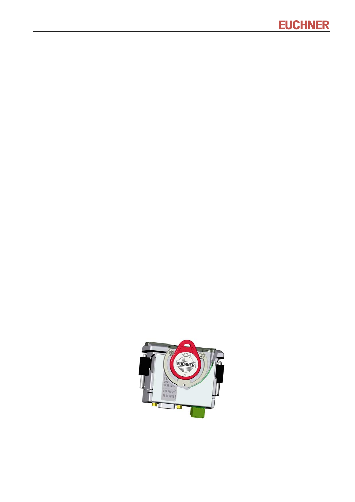
The Electronic-Keys are tag shaped. The complete, battery-less transponder with memory chip and antenna is
integrated into the Electronic-Key.
For operation, the Electronic-Key is inserted in the Electronic-Key adapter and is held in place by a spring clip.
The power supply for the transponder and the data are transferred without contact between the Electronic-Key
adapter and the Electronic-Key.
Cut-away illustration of Electronic-Key adapter
The data carrier in the Electronic-Key is equipped with a combined memory:
116 bytes E²PROM (programmable) plus an additional 8 bytes ROM (serial number)
088796-02-03/05 Subject to technical modifications Page 7/24
Page 8
Manual EKS Electronic-Key Adapter serial
4 Technical data
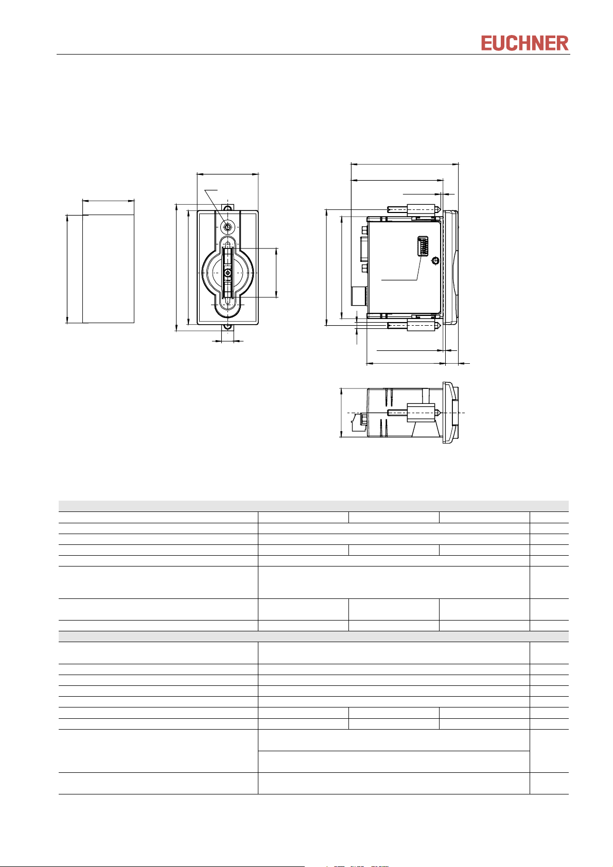
4.1 Dimension drawing, Electronic-Key adapter/front panel cut-out
Front panel cut-out
according to DIN 43700
33
68
40
LED
76
83
75
8
32
67
M4
32
70,5
60,7
max. 4mm
DIP switch
1,5 Rubber seal
51,5
8,5
4.2 Technical data, Electronic-Key adapter
General parameters Value Unit
min. typ. max.
Housing Plastic (PA 6 GF30 gray)
Degree of protection according to EN 60529 IP 67 in mounted condition
Ambient temperature at UB = DC 24 V 0 + 55 °C
Mounting cut-out according to DIN 43700 33 x 68 mm
Connection type for power supply Miniature plug connector 3-pin,
Conductor cross-section max. 1.5 mm²,
tightening torque 0.22 Nm
Operating voltage UB
(regulated, residual ripple < 5 %)
Current consumption 100 mA
Interface, data transfer
Interface to host control serial RS232 / RS422
Transfer protocol 3964R
Baud rate 9.6 kbaud
Data format 1 start bit, 8 data bits, 1 parity bit (even parity), 1 stop bit
Connection type for serial interface Sub-D 9-pin socket
Cable length RS232 5m
Cable length RS422 1000 m
Out output
Level
LED display Green: "Ready" (in operation)
20 24 28 DC V
(selectable via DIP switch)
Active if there is a functional Electronic-Key in the Electronic-
Key adapter (Electronic-Key active).
Pin 8 Sub-D socket serial interface: RS232
Pin 3 screw terminal power supply: +24 V DC
Yellow: "Electronic-Key active" *
* The LED illuminates yellow if there is a functional Electronic-Key in the Electronic-Key adapter.
088796-02-03/05 Subject to technical modifications Page 8/24
Page 9

Manual EKS Electronic-Key Adapter serial
4.3 Pin assignment
4.3.1 Serial interface socket
Pin assignment
RS232 RS422
Function
earth
Function
earth
Function
Active if there is a functional Electronic-Key in the ElectronicKey adapter, level RS232 (Electronic-Key active). Used as
CTS signal
Electrically connected to the housing
5
9
SUB-D socket
1
6
9-pin
PIN
1 - RxD - Data wire B1 receive data (signal B1 receive data)
2 TxD - Transmit data
3 RxD - Receive data
4--5 GND - Signal ground
6 - TxD - Data wire B transmit data (signal B transmit data)
7 - TxD + Data wire A transmit data (signal A transmit data)
8OUT-
9 - RxD + Data wire A1 receive data (signal A1 receive data)
Housing
4.3.2 Power supply and Out signal 24 V screw terminals
The coded plug for the connection of the power supply is included with the Electronic-Key adapter.
PIN Designation Function
123
1 UB Power supply DC + 24 V
Coded plug, 3-pin
with screw terminals
Max. conductor cross-section 1.5 mm²
Tightening torque 0.22 Nm
2 0V Power supply DC 0 V
Active if there is a functional Electronic-Key in
3OUT
the Electronic-Key adapter,
level DC +24 V (Electronic-Key active)
088796-02-03/05 Subject to technical modifications Page 9/24
Page 10

Manual EKS Electronic-Key Adapter serial
4.4 DIP switch settings
Using the DIP switches S1 to S8, various parameters can be set.
Write protection can be enabled using DIP switch S1. In this way the writing of data to the Electronic-Key
read/write is prevented.
The settings are only applied when the power supply is switched on.
DIP switches, 8-pole:
ON
123
switch
* The read-only transponder type can also be read using the Electronic-Key adapter with serial interface. However, we do
not recommend using this transponder type in new installations.
4567
DIP
S8 OFF = Electronic-Key read/write ON = Electronic-Key read-only * OFF
S7 OFF
S6 OFF
S5 OFF
S4 ON OFF ON
S3 ON
S2 OFF
S1 ON = write protection for Electronic-Key read/write OFF
Functions Factory setting
8
RS232
ON
RS422
ON
It is imperative that all DIP switches without a function (S2 and S5 to S7) are set to OFF! In this way
problems with any functions added in the future will be avoided.
4.5 OUT output
The OUT output signal changes from inactive (0) to active (1) if there is a functional Electronic-Key in the
Electronic-Key adapter. This signal can be used for control purposes to detect whether there is a Electronic-Key
in the Electronic-Key adapter. The function is identical to the "Electronic-Key active" LED display (yellow).
The OUT output is available on the Electronic-Key adapter with two different levels. On pin 8 of the serial
interface socket with RS232 level (for use as CTS signal on the RS232 interface) and on pin 3 of the power
supply screw terminal with a level of DC + 24 V (inactive = 0 V, active = DC + 24 V) for use as a handshake
signal e.g. with a PLC.
4.6 LED display
The operating statuses of the Electronic-Key adapter are displayed on a 2-color LED on the front.
The illumination of the LED with any color indicates that the operating voltage is present.
Color Operating status Description
Green Ready Electronic-Key adapter supplied with power and ready.
Yellow Electronic-Key active There is an Electronic-Key in the Electronic-Key adapter and it has been detected.
088796-02-03/05 Subject to technical modifications Page 10/24
Page 11

Manual EKS Electronic-Key Adapter serial
5 Mounting
Mounting must be performed only by authorized personnel.
To achieve the degree of protection IP 67, it is necessary to install the Electronic-Key adapter in a
clean, flat metal plate at least 2 mm thick and to tighten the screws to a tightening torque of at least
0.25 Nm.
The Electronic-Key adapter is intended for mounting in control panels with a cut-out measuring
33 mm x 68 mm according to DIN 43700 (see page 8 chapter 4.1 Dimension drawing, Electronic-Key
adapter/front panel cut-out). The device is fastened using screw clamp elements from the rear side of the panel.
The screw clamp elements for front panel mounting are included with the Electronic-Key adapter.
1. Insert Electronic-Key adapter, with seal already bonded in place, into the mounting cut-out from the front.
2. Insert screw clamp elements in the housing of the Electronic-Key adapter and tighten to min. 0.25 Nm.
After mounting, again check the Electronic-Key adapter for firm seating and correct sealing of the front
plate.
088796-02-03/05 Subject to technical modifications Page 11/24
Page 12

Manual EKS Electronic-Key Adapter serial
6 Electrical connection
Electrical connection may only be performed by authorized personnel trained in EMC and with the
device and wiring isolated.
For use and operation as per the requirements, a power supply for use in class 2 circuits must
be used.
The Electronic-Key adapter is only allowed to be connected if it is electrically isolated.
Otherwise the Electronic-Key adapter may be damaged.
If connected incorrectly, the Electronic-Key adapter may be damaged.
Observe electrical characteristics and pin assignment (see page 8 chapter 4.2 Technical data,
Electronic-Key adapter).
All the electrical connections must either be isolated from the mains supply by a safety transformer
according to IEC/EN 61558-2-6 with limited output voltage in the event of a fault, or by other equivalent
isolation measures.
When installing connections, the operating organization must ensure compliance with the EMC safety
requirements in accordance with EN 55011 and EN 61000-6-2.
The equipotential bonding system of the machine installation must comply with EN 60204-1, chapter 8,
Potentialausgleich (Equipotential bonding).
Do not lay connection cables in the immediate vicinity of sources of interference.
6.1 Connection of power supply
(For information on pin assignment see page 9 chapter 4.3.2 Power supply )
It is imperative that the following points are observed:
The connections must be made as appropriate to maintain EMC performance.
A power supply of suitable EMC performance must be used for the power supply.
Conductor cross-section maximum 1.5 mm².
Tighten the terminal screws on the plug to 0.22 Nm.
6.2 Connection of function earth
The function earth must be electrically connected via the interface cable screen and the electrically conductive
connector housing to the Electronic-Key adapter housing.
The function earth must be connected to PE!
088796-02-03/05 Subject to technical modifications Page 12/24
Page 13

Manual EKS Electronic-Key Adapter serial
6.3 Serial interface connection
6.3.1 RS232 wiring diagram
EKS
9 - Pin
TxD
RxD
GND
OUT
2
3
4
5
6
7
8
6.3.2 RS422 wiring diagram
TxD+
7
RxD+
9 - Pin
PC or PLC
2
Receive Data
3
Tra nsm i t Da ta
4
Data Term Ready
5
Signal Ground
6
Data Set Ready
7
Request to Send
8
Clear to Send
25 - Pin
3
2
20
7
6
4
5
Shield
TxD-
RxD+
9
1
RxD-
GND GND
5
RxD-
TxD+
TxD-
088796-02-03/05 Subject to technical modifications Page 13/24
Page 14

Manual EKS Electronic-Key Adapter serial
7 Setup
Setup is to be performed in the following sequence:
1. Set the DIP switches on the Electronic-Key adapter
(see page 10 chapter 4.4).
2. Check mounting and electrical connection are correct
(see page 11 chapter 5 Mounting and page 12 chapter 6 Electrical connection).
3. After the power supply is switched on, the LED on the front of the Electronic-Key adapter illuminates green.
This indicates that the power supply is present.
4. Insert Electronic-Key in the Electronic-Key adapter. The LED changes to yellow.
088796-02-03/05 Subject to technical modifications Page 14/24
Page 15

Manual EKS Electronic-Key Adapter serial
8 Operating the Electronic-Key-System using the serial
interface
8.1 Special features of the serial interface
If there is an Electronic-Key within the operating distance of the Electronic-Key adapter, the LED on the front
changes from green to yellow. At the same time the OUT handshake signal (for use as CTS signal) changes
from inactive (0) to active (1). This signal can be used for control purposes to detect whether there is an
Electronic-Key in the Electronic-Key adapter.
8.2 Communication
In this chapter primarily the communication between PC/PLC and the Electronic-Key adapter (referred to as
device in the following tables) is described.
The Electronic-Key adapter is addressed over the serial interface. The commands are given over this serial
interface.
The transfer messages for the commands
Program (write) Electronic-Key
Read Electronic-Key
are based on the transfer protocol 3964R [1]
8.3 Basic message structure
Every command and any related data blocks are transferred from and to the Electronic-Key adapter in a
message core within the message frame as per the protocol 3964R (Figure 1: Basic command structure in the
3964R protocol).
In the 3964R protocol, the recipient acknowledges the message received by sending back an acknowledgement
character (DLE). If the acknowledgement is negative (NAK), the complete protocol is repeated. If it is not
possible to correctly transfer the protocol after a total of six attempts, the process is aborted.
Acknowledgement from
the recipient
+ -
DLE NAK
DLE NAK
Connection setup
Message data max. 128 bytes
Message core
Connection termination
Figure 1: Basic command structure in the 3964R protocol
Description Byte no.
3964R procedure start STX
Number of message bytes 0
Command identification
Device address 3 01
User data description
User data 7 ... n
3964R procedure termination
1
2
4
5
6
Transmit data in
ASCII format
T or R
command
hex
Start address
Start address
Number of items of data
DLE
ETX
BCC
088796-02-03/05 Subject to technical modifications Page 15/24
Page 16

Manual EKS Electronic-Key Adapter serial
8.3.1 Special features of the 3964R data transfer protocol [1]
The 3964R data transfer protocol is a comparatively reliable protocol for the electronic exchange of data
between PC/control system and a peripheral connected, because the data transfer is performed using a
standardized protocol.
On control systems with an integrated 3964R driver (see e. g. [1] ) it is not necessary for the user to become
involved in the details of setting up the connection and data integrity. Here it is sufficient to use the program to
pass the message core to the 3964R driver.
However, on control systems without a 3964R driver or on the connection of the Electronic-Key adapter to the
PC, the user must also program the connection setup as well as retries and DLE duplication.
Integration of the Electronic-Key adapter with serial interface into the user’s PC application is supported by an
optionally available ActiveX module (order no. 084 708) (usable if user programs on MS Windows® support
ActiveX). EKS can thus be used in conjunction with process visualization.
8.3.1.1 Basic information on data transfer procedures using a protocol [1]
Numerous conventions must be agreed for a data transfer procedure; codes, operating modes, transfer speeds
and the algorithmic process for the transfer. The definition of this algorithmic process is termed the transfer
protocol (for short: protocol).
A transfer protocol in general defines the following phases of the data transfer:
Connection setup: request from A to B for the transfer of data
Data transfer from A to B
Connection termination: conclusion of the transfer of data
8.3.1.2 The 3964R transfer protocol [1]
Unlike protocol-free data transfer procedures, 3964R is a data transfer with protocol. This means that the actual
data that need to be transferred are enclosed in specific control characters. The 3964R driver permits
comparatively reliable data transfer as the recipient must signal to the sender readiness to receive (connection
setup) and acknowledge correct reception after completion of the data transfer. W ith the 3964R transfer
protocol, data integrity is increased by an additional block check character.
The 3964R driver interprets the following control characters:
DLE (10
STX (02
NAK (15
ETX (03
) Data Link Escape
hex
) Start of Text
hex
) Negative Acknowledgement
hex
) End of Text
hex
At the end of each data block in the 3964R transfer protocol, a block check character (for short: BCC) is sent
to assure data integrity. The block check character is the even longitudinal parity (XOR operator on all data
bytes) of a block sent or received. The block check character is formed starting with the first byte of the
message core after the connection is setup and ends after the characters DLE and ETX during connection
termination.
8.3.1.3 The control system sends [1]
To setup the connection, the control system sends the control character STX. If, before the acknowledgement
delay time (ADT, typically: 2 s) elapses the peripheral responds with the control character DLE, the control
system switches to transfer mode. If the peripheral responds with the control character NAK, any other
character (except DLE) or the acknowledgement delay time elapses without a reaction, the attempt to setup the
connection has failed. After a total of 6 unsuccessful attempts (3964R protocol specification) the process is
aborted. If the attempt to setup the connection is successful, the characters with the information as contained in
the send buffer in the control system are transferred to the peripheral at the selected transfer speed.
088796-02-03/05 Subject to technical modifications Page 16/24
Page 17

Manual EKS Electronic-Key Adapter serial
The peripheral monitors the amount of time between the incoming characters. The gap between two characters
must not be more than the character delay time (CDT, typically: 100 ms).
All 10
values contained in the message core must be sent twice so that the recipient recognizes that here
hex
information is being transferred and not the control character DLE (DLE duplication).
After the data has been sent, the control system adds the following characters as an end identifier: DLE ETX
BCC.
Then the control system waits for an acknowledgement character from the peripheral. If the peripheral sends
the control character DLE within the acknowledgement delay time (ADT, typically: 2 s), the data block has been
received correctly. If, on the other hand, the peripheral responds with the control character NAK, any other
character or the acknowledgement delay time elapses without a reaction, the control system starts again from
the beginning by setting up a connection with STX. After a total of 6 unsuccessful attempts (3964R protocol
specification) to send the data block, the process is aborted and the control system sends the control character
NAK to the peripheral.
8.3.1.4 The control system receives [1]
If the control system receives the control character STX from the peripheral when the control system is idle, it
responds with DLE. If the control system receives another character (except STX) when it is idle, it waits until
the character delay time (CDT, typically: 100 ms) has elapsed and then sends the control character NAK.
After each character, the next character is awaited during the character delay time (CDT). If the character delay
time elapses without the reception of a character, the control character NAK is sent to the peripheral.
When the control system detects the character string DLE ETX BCC, it ends reception. The control system
compares the block check character BCC with the longitudinal parity calculated internally. If the block check
character is correct and no other reception errors have occurred, the control system sends the control character
DLE. If the BCC is erroneous, the control character NAK is sent to the peripheral. A retry is then expected. If it
is not possible to receive the block correctly after a total of 6 attempts (3964R protocol specification) or the retry
is not started by the peripheral within the block waiting time of 4 s, the control system aborts the reception.
If transfer errors occur during reception (lost characters, frame errors, parity errors), the control system
continues to receive data until the connection is terminated and then sends the control character NAK to the
peripheral. Then a retry in the form described above is awaited.
8.3.1.5 Summary of the most important points
DLE duplication:
For the control system to be able to differentiate between the control character DLE and a randomly
occurring 10
value in the information to be transferred, a 10
with the 10
value as a character in the information to be transferred, on the occurrence of a 10
hex
value occurs in the message core, this character must be transferred again so that it is not
hex
value must be sent again. This means that if a byte
hex
hex
interpreted by the receiving end as the control character DLE for terminating the connection.
The block check character (BCC):
At the end of each data block, a block check character is sent to assure data integrity. The block check
character is the even longitudinal parity (XOR operator on all data bytes) of a block sent or received. The
block check character is formed starting with the first byte of the message core after the connection is
setup and ends after the characters DLE and ETX during connection termination.
Retries on errors:
If an error occurs for any reason during the data transfer, a total of 6 attempts are made to transfer the
data correctly.
088796-02-03/05 Subject to technical modifications Page 17/24
Page 18

Manual EKS Electronic-Key Adapter serial
8.4 Commands for writing and reading an Electronic-Key read/write
Write and read processes are always initiated by the PC/PLC (control system) using a "command message".
The Electronic-Key-System then sends a reply message to the control system.
PC/PLC (control system) Electronic-Key-System
Command message
−→
Reply message
←
On Electronic-Keys read/write with 116 bytes, the memory is organized in 4-byte blocks. This means a
multiple of 4-byte sized blocks must always be written.
The start address must be given in the range byte number 0 to byte number 112, always in 4-byte steps
(byte number 0, 4, 8 ... 112)!
However, during reading it is possible to access the memory by bytes without the above mentioned
restriction during writing.
8.4.1 Write process
When this command is used, the Electronic-Key must be in the Electronic-Key adapter and is only
allowed to be removed from within the operating distance after reception of the reply message.
Command message (message core, PC/PLC → EKS, see Figure 2):
TP (device addr.) (start addr. user data) (number of bytes of user data) (user data)
Reply message (message core, EKS → PC/PLC, see Figure 3):
RF (device addr.) (00
Byte no. Description
0 Number of message bytes 0B ... 7B 11 ... 123
1
2
3 Device address 01 1
4
5
6 Number of bytes of user data 04 ... 74 4 ... 116
7 ... 122 User data ASCII or hexadecimal or BCD (code transparent)
Command identification
Start address for the user data
Figure 2: Command message write Electronic-Key read/write (message core)
hex
,00
) (status number)
hex
Contents
ASCII hexadecimal decimal
T
P
54
50
00
00 ... 70
84
80
0
0 ... 112
088796-02-03/05 Subject to technical modifications Page 18/24
Page 19

Manual EKS Electronic-Key Adapter serial
Byte no. Description
0 Number of message bytes 07 7
1
2
3 Device address 01 1
4
5
6 Status number *
Command identification
Padding data
ASCII hexadecimal decimal
R
F
Figure 3: Reply message write Electronic-Key read/write - status (message core)
* Status number 00
: No error
hex
02
: Electronic-Key not in the operating distance
hex
(For further status numbers see chapter 8.7)
8.4.2 Read process
Command message (message core, PC/PLC → EKS, see Figure 3):
TL (device addr.) (start addr. user data) (number of bytes of user data)
Contents
52
46
00
00
82
70
0
0
Reply message (message core, EKS → PC/PLC, see Figure 5 or Figure 6):
For this command there are two possible replies:
RL (device addr.) (start addr. user data) (number of bytes of user data) (user data)
or
RF (device addr.) (00
hex
,00
) (status number)
hex
The reply message RL (see Figure 5) stands for correct reception of the data.
If an Electronic-Key cannot be read, an RF reply message is received (see Figure 6). The status number then
indicates the cause of the error.
Byte no. Description
0 Number of message bytes 07 7
1
2
3 Device address 01 1
4
5 Start address for the user data
6 Number of bytes of user data 01 ... 74 1 ... 116
Command identification
ASCII hexadecimal decimal
T
L
Contents
54
4C
00
00 ... 73
84
76
0
0 ... 115
Figure 4: Command message read Electronic-Key read/write (message core)
088796-02-03/05 Subject to technical modifications Page 19/24
Page 20

Manual EKS Electronic-Key Adapter serial
Byte no. Description
0 Number of message bytes 08 ... 7B 8 ... 123
1
2
3 Device address 01 1
4
5 Start address for the user data
6 Number of bytes of user data 01 ... 74 1 ... 116
7 ... 122 User data ASCII or hexadecimal or BCD (code transparent)
Command identification
ASCII hexadecimal decimal
R
L
Contents
52
4C
00
00 ... 73
Figure 5: Reply message read Electronic-Key read/write (message core)
Byte no. Description
0 Number of message bytes 07 7
1
2
3 Device address 01 1
4
5
6 Status number *
Command identification
Padding data
ASCII hexadecimal decimal
R
F
Contents
52
46
00
00
Figure 6: Reply message read Electronic-Key read/write - status (message core)
* Status number 02
: Electronic-Key not in the operating distance
hex
(For further status numbers see chapter 8.7)
82
76
0
0 ... 115
82
70
0
0
8.4.3 Reading the serial number
The Electronic-Key read/write contains a unique 8-byte serial number. This number is written by laser during the
Electronic-Key production process and can never be changed or deleted. The serial number is used for reliable
identification of each individual Electronic-Key. It is necessary that all 8 bytes are completely evaluated for
reliable differentiation. The serial number is appended to the freely programmable user data.
The serial number can be read using the command TL (see section 8.4.2 Read process) using the start address
byte no. 116 and 8 as the number of bytes.
088796-02-03/05 Subject to technical modifications Page 20/24
Page 21

Manual EKS Electronic-Key Adapter serial
8.5 Command for resetting
Using the command message TA the Electronic-Key adapter can be reset to its initial condition via the software.
Command message (message core, PC/PLC → EKS, see Figure 7):
TA (device addr.) (00
hex
, 00
hex
) (00
hex
)
Reply message (message core, EKS → PC/PLC, see Figure 8):
RF (device addr.) (00
The reply message RF with status number 00
hex
, 00
hex
) (00
hex
)
(see Figure 8) stands for correct processing of the cancel
hex
command.
Byte no. Description
0 Number of message bytes 07 7
1
2
3 Device address 01 1
4
5
6 Number of bytes of user data 00 0
Command identification
Start address for the user data
Figure 7: Command message cancel (message core)
Byte no. Description
0 Number of message bytes 07 7
1
2
3 Device address 01 1
4
5
6 Status number 00 0
Command identification
Padding data
Figure 8: Reply message cancel (message core)
Contents
ASCII hexadecimal decimal
T
A
ASCII hexadecimal decimal
R
F
54
41
00
00
Contents
52
46
00
00
84
65
0
0
82
70
0
0
088796-02-03/05 Subject to technical modifications Page 21/24
Page 22

Manual EKS Electronic-Key Adapter serial
8.6 Command overview
Description Command message Reply message
Program (write) Electronic-Key
Read Electronic-Key
(also read the serial number)
TP (see chapter 8.4.1) RF (see chapter 8.4.1)
TL (see chapter 8.4.2 and 8.4.3) RL (see chapter 8.4.2)
or
RF (see chapter 8.4.2)
Reset device
TA (see chapter 8.5) RF (see chapter 8.5)
8.7 Status numbers
Value Description
00
02
03
06
17
18
4x
50
hex
hex
hex
hex
hex
hex
hex
hex
No error
Electronic-Key not in the operating distance
Parity bit error on Electronic-Key read-only
Write process aborted. Start address or number of bytes is not a multiple of the block size 4
Read attempt when the Electronic-Key adapter is set to Electronic-Key read/write and an Electronic-Key
read-only is inserted
Read attempt when the Electronic-Key adapter is set to Electronic-Key read-only and an Electronic-Key
read/write is inserted
General Electronic-Key communication error (renewed write or read necessary)
Write attempt despite enabled write protection
088796-02-03/05 Subject to technical modifications Page 22/24
Page 23

Manual EKS Electronic-Key Adapter serial
9 Exclusion of liability
Exclusion of liability under the following conditions:
if the unit is not used for its intended purpose
non-compliance with safety regulations
if mounting and electrical connection are carried out by unauthorized personnel
if modifications are made
10 Service and repair
No servicing is required.
Remove dirt from the Electronic-Key and the Electronic-Key adapter using a soft cloth and solvent-free,
non-abrasive cleaning agents.
Repairs are only to be made by the manufacturer.
11 Guarantee
The “General Terms and Conditions” of EUCHNER GmbH + Co. KG apply.
12 Bibliography
[1] SIEMENS AG manuals, connection components for S7 control systems
Controler (PLC) S7-300CPU-Data
CPUs 312C to 314C-2DP/PtP
Only RS422/485
Point-to-point communication CP 340 SIEMENS order No.
Installation and parameter assignment 6ES7340-1AH00-8BA0
Point-to-point communication CP 341 SIEMENS order No.
Installation and parameter assignment 6ES7341-1AH00-8BA0
Point-to-point communication CP 441 SIEMENS order No.
Installation and parameter assignment 6ES7441-2AA00-8BA0
088796-02-03/05 Subject to technical modifications Page 23/24
Page 24

EUCHNER GmbH + Co. KG Telefon 0711 / 75 97 - 0
Kohlhammerstraße 16 Telefax 0711 / 75 33 16
D-70771 Leinfelden-Echterdingen
www.euchner.de
.
info@euchner.de
 Loading...