

EUCHNER EKS-A-IIX-G01-ST02/03, EKS-A-IIXA-G01-ST02/03/04, EKS-A-AIX-G18, EKS-A-AIXA-G18 Application
Page 1
Application
Integration of EKS with PROFINET interface in BECKHOFF TwinCAT 3
EN
Page 2

Application EKS
Integration of EKS with PROFINET interface in BECKHOFF TwinCAT 3
Contents
1. About this document ............................................................................................. 3
1.1. Version ..........................................................................................................................................3
1.2. Scope ............................................................................................................................................3
1.3. Target group ..................................................................................................................................3
1.4. Supplementary documents ..............................................................................................................3
1.5. Notice ............................................................................................................................................3
2. Components/modules used .................................................................................. 4
2.1. EUCHNER ......................................................................................................................................4
2.2. Others ...........................................................................................................................................4
2.3. Software ........................................................................................................................................4
3. Functional description ........................................................................................... 4
4. Overview of the communication data ..................................................................... 5
4.1. Input ..............................................................................................................................................5
4.2. Output ...........................................................................................................................................5
5. Installing the GSD le ............................................................................................ 6
6. Setting the control system parameters .................................................................. 7
7. Conguring and setting the parameters of the EKS with PROFINET interface .......... 8
7.1. Conguring the PROFINET network ...................................................................................................8
7.2. Conguring the EKS with PROFINET interface .................................................................................... 9
7.3. Setting the EKS parameters ..........................................................................................................11
7.4. Assigning PROFINET device names to the EKS ................................................................................12
8. Using the BECKHOFF library ............................................................................... 14
8.1. Installation of the library ................................................................................................................14
8.2. Calling the library and description of the block interface ..................................................................16
8.2.1. Calling the library ..........................................................................................................16
8.2.2. Description of the block interfaces .................................................................................18
8.2.3. Complete EKS data type call ..........................................................................................18
9. Linking the input and output areas in EKS ............................................................ 19
10. Reading and writing Electronic-Key data ............................................................. 21
10.1. Transferring program to the PLC ....................................................................................................21
10.2. Reading content of the memory in the Electronic-Key using the block interface ..................................21
10.3. Writing content of the memory in the Electronic-Key using the block interface....................................21
11. Important note – please observe carefully! ......................................................... 22
2
(Application) AP000240-01-01/19
Page 3

Application EKS
Integration of EKS with PROFINET interface in BECKHOFF TwinCAT 3
1. About this document
1.1. Version
Version Date Change/addition Chapter
01-01/19 10.01.2019 Prepared All
1.2. Scope
The purpose of this document is the integration and conguration of the EKS with PROFINET interface (from device version
as per table) in BECKHOFF TwinCAT 3.
Order no. Designation Device version
106305 EKS-A-IIX-G01-ST02/03 V3.0.0
106306 EKS-A-IIXA-G01-ST02/03/04 V3.0.0
122352 EKS-A-AIX-G18 V1.X.X
122353 EKS-A-AIXA-G18 V1.X.X
1.3. Target group
Design engineers and installation planners for safety systems on machines, as well as setup and servicing staff possessing
special expertise in handling safety components as well as expertise in the installation, setup, programming and diagnostics
of programmable logic controllers (PLC) and bus systems.
1.4. Supplementary documents
The overall documentation for this application consists of the following documents:
Document title
(document number)
Manual
(2516210)
Possibly enclosed data
sheets
Contents
Electronic-Key-System
Manual EKS and EKS FSA with PROFINET IO interface
Item-specic information about deviations or additions
www
1.5. Notice
This application is based on the manual for the EKS with PROFINET interface. Please refer to the manual for the technical
details and other information. In the rest of this document the EKS with PROFINET interface is referred to as the "EKS" for short.
AP000240-01-01/19 (Application)
EN
3
Page 4

Application EKS
Integration of EKS with PROFINET interface in BECKHOFF TwinCAT 3
2. Components/modules used
2.1. EUCHNER
Description Order number / item
EKS with PROFINET interface 106305 / EKS-A-IIX-G01-ST02/03
TIP!
More information and downloads about the aforementioned EUCHNER products can be found at www.euchner.com.
Simply enter the order number in the search box.
2.2. Others
Description Order number / item
CX9020-0110-M930 CX9020-0110-M930
2.3. Software
Description Version
Microsoft Visual Studio 2013 Shell (Integrated) Version 12.0.21005.1 REL
Microsoft .NET Framework Version 4.7.03056
TcMeasurement 1.0
TcProjectCompare 1.0.0.9
TcTargetBrowserPackage Extension 1.0
TcXaeDebuggerLiveWatch 1.0
TcXaeHelper 1.0
TcXaeModules 1.0
TwinCAT XAE Base 3.1.0.0
TwinCAT XAE EventLogger 1.0
TwinCAT XAE PLC 3.1.0.0
3. Functional description
EKS PROFINET devices are read/write systems with electronics for the inductive bidirectional interface to the transponder
and the interface electronics.
The system is connected via the integrated PROFINET interface, which is designed as an RJ45 socket. A separate switch
may be required for the PROFINET connection. The EKS does not have an integrated switch.
The current state of the Electronic-Key adapter is displayed using a 3-color LED.
The Electronic-Key is placed on the Electronic-Key adapter for operation. The power supply for the transponder and the data
are transferred between the Electronic-Key adapter and the Electronic-Key without using any contacts.
4
(Application) AP000240-01-01/19
Page 5

Application EKS
Integration of EKS with PROFINET interface in BECKHOFF TwinCAT 3
4. Overview of the communication data
4.1. Input
PROFINET Bit 7 Bit 6 Bit 5 Bit 4 Bit 3 Bit 2 Bit 1 Bit 0
Byte 0
(Status byte)
PROFINET Description Function
Byte 1
.
.
.
Byte 127
4.2. Output
PROFINET Bit 7 Bit 6 Bit 5 Bit 4 Bit 3 Bit 2 Bit 1 Bit 0
Byte 0
(command byte)
Job in progress Job nished - - - - Electronic-Key
Receive data
- - - - - - - Write Electron-
Max. 124 bytes user data from the Electronic-Key plus 3 bytes reserve. If fewer bytes of data were
selected during conguration, these are lled with 0hex.
detected
Device ready for
operation
ic-Key
PROFINET Description Function
Byte 1
Byte 2
Byte 3 Not used
Byte 4
.
.
.
Byte 119
Byte 120
.
.
Byte 127
Start address
Number of bytes
Transmit data
Not used
Denes rst byte in the memory in the Electronic-Key that is written on setting bit no. 0 in the
command byte. Start address of user data: byte no. 0, 4, 8 … 112.
Denes the number of bytes in the memory in the Electronic-Key that are written on setting bit no.
0 in the command byte. Number of bytes of user data: 4, 8, 12 … 116 bytes.
If bit no. 0 in the command byte is set to 1, the content of these bytes is written to the Electronic-Key
starting from the start address dened.
TIP!
You will nd further information in the manual.
NOTE!
On the Electronic-Key read/write with 116 bytes freely programmable, the memory is organized in
4-byte blocks. This means the start address for writing must be given in the range byte number 0 to
byte number 112, always in 4-byte steps (byte number 0, 4, 8 ... 112). Also a multiple of 4-byte sized
blocks must always be written (4, 8, 12 ... 116 bytes).
During reading it is possible to access the memory byte-by-byte without the above-mentioned restriction for writing.
AP000240-01-01/19 (Application)
EN
5
Page 6

Application EKS
Integration of EKS with PROFINET interface in BECKHOFF TwinCAT 3
5. Installing the GSD le
You will require the corresponding GSD le in the GSDML format to integrate the EKS into TwinCAT 3, depending on the
design of the EKS:
Design Related GSD le
compact
(Order No. 106305/106306)
modular
(Order No. 122352/122353)
You will nd the GSD les in the download area at www.euchner.com. Always use the latest GSD le.
Please proceed as follows to integrate the GSD le in TwinCAT 3:
Open the path as shown in Figure 1 and then add the unpacked GSDML and bitmap le.
GSDML-V2.31-Euchner-EKS_3.x.x_109539-YYYYMMDD.xml
GSDML-V2.31-EUCHNER-EKS_PN_modular_126145-YYYYMMDD.xml
Figure 1: Adding GSD le
6
(Application) AP000240-01-01/19
Page 7
Integration of EKS with PROFINET interface in BECKHOFF TwinCAT 3
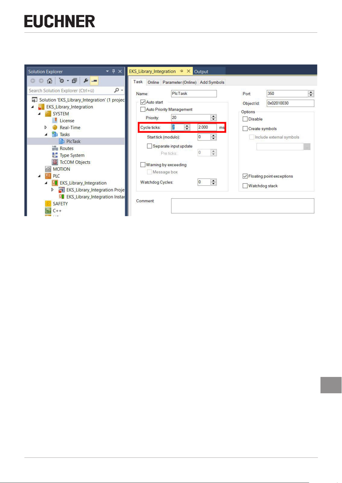
6. Setting the control system parameters
Specify the cycle time for the PlcTask. Use the value 2 for this purpose.
Application EKS
Figure 2: Setting the control system parameters
EN
AP000240-01-01/19 (Application)
7
Page 8
Application EKS
Integration of EKS with PROFINET interface in BECKHOFF TwinCAT 3
7. Conguring and setting the parameters of the EKS with PROFINET interface
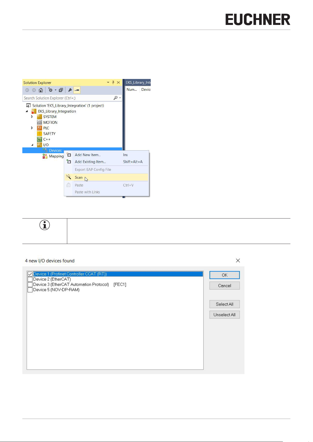
7.1. Conguring the PROFINET network
Add the PROFINET network as follows:
1. In Solution Explorer click I/O, right-click Devices and choose Scan.
Figure 3: Adding PROFINET network
NOTE!
To undertake scans the TwinCAT must be in the Cong Mode.
2. Select the PROFINET controller and accept using OK.
Figure 4: Selection of PROFINET controller
8
(Application) AP000240-01-01/19
Page 9

Application EKS
Integration of EKS with PROFINET interface in BECKHOFF TwinCAT 3
3. You are then prompted as to whether a search is to be made for additional boxes (devices). Please answer this prompt
with No because it cannot be ensured the correct EKS will be congured.
Figure 5: Rejecting search for devices
7.2. Conguring the EKS with PROFINET interface
4. Right-click the PROFINET controller and then choose Add New Item...
Figure 6: Adding a device
AP000240-01-01/19 (Application)
EN
9
Page 10

Application EKS
Integration of EKS with PROFINET interface in BECKHOFF TwinCAT 3
5. Select the corresponding GSDML le.
Figure 7: Selection of the GSDML le
6. Select the corresponding EKS.
Figure 8: Selection of the EKS
10
(Application) AP000240-01-01/19
Page 11

Integration of EKS with PROFINET interface in BECKHOFF TwinCAT 3
7.3. Setting the EKS parameters
The following PROFINET parameters must be set:
Ì Device name (factory setting from GSD le): [eks-pn].
Ì IP address: xed
Application EKS
Figure 9: PROFINET parameters
Ì IO cycle real time settings
These values are already set to the recommended default values.
EN
Figure 10: PROFINET real time settings
AP000240-01-01/19 (Application)
11
Page 12

Application EKS
Integration of EKS with PROFINET interface in BECKHOFF TwinCAT 3
7.4. Assigning PROFINET device names to the EKS
There are two ways of assigning a device name to the EKS. Either using the EKS web browser (see manual) or using TwinCAT.
In the following we show name assignment using TwinCAT.
1. To assign the name to the EKS using TwinCAT, please right-click the PROFINET controller and then choose Scan.
Figure 11: Searching for devices online
12
(Application) AP000240-01-01/19
Page 13

Integration of EKS with PROFINET interface in BECKHOFF TwinCAT 3
2. Select the EKS from the list. Enter the device name in Stationname and accept using Set Stationname.
Application EKS
Figure 12: Assigning device name
TIP!
As an alternative to MAC address comparison, you can use Start Signal to see whether you have
selected the correct subscriber. The LED ashes on the EKS.
EN
AP000240-01-01/19 (Application)
13
Page 14

Application EKS
Integration of EKS with PROFINET interface in BECKHOFF TwinCAT 3
8. Using the BECKHOFF library
The library is intended to assist you during programming. The library contains pre-prepared data that you can then use.
Open the page with the EKS applications in the download area at www.euchner.com and download the library for the EKS.
8.1. Installation of the library
1. Click the PLC tab and open the Library Repository.
2. Install the library and select the path where you have saved the library.
Figure 13: Installing library
NOTE!
As soon as the library is installed, it is displayed in (Miscellaneous).
14
(Application) AP000240-01-01/19
Page 15

Application EKS
Integration of EKS with PROFINET interface in BECKHOFF TwinCAT 3
3. Next you must add the library to the project. In Solution Explorer, right-click References and then choose Add library.
Figure 14: Adding library to the project
4. Select the library prepared by EUCHNER.
Figure 15: Selection of the library
AP000240-01-01/19 (Application)
EN
15
Page 16

Application EKS
Integration of EKS with PROFINET interface in BECKHOFF TwinCAT 3
8.2. Calling the library and description of the block interface
8.2.1. Calling the library
1. To be able to use the library, the blocks from the library must be called in the main program (MAIN). For this purpose,
open the block and select the programming section. You can select the blocks with the aid of the Input Assistant that
can be opened using the right mouse button or the F2 key.
Figure 16: Opening the Input Assistant
2. You will nd the library on the Categories tab. Select Function Blocks. You will nd the EUCHNER library in the window
on the right. You can select two function blocks from the library. EKS_Read is required to read the Electronic-Key data
and EKS_Write to write data to the Electronic-Key.
Figure 17: Selecting the blocks (function blocks)
16
(Application) AP000240-01-01/19
Page 17

Application EKS
Integration of EKS with PROFINET interface in BECKHOFF TwinCAT 3
3. The blocks must be instanced. In our example we assign the name EKS_Read_01 for the data type EKS_Read. Then you
can repeat this process (step 1 to 3) for the data type EKS_Write.
Figure 18: Declaring the data type
4. The program must now be built. In this way the input and output variables for the project are generated; these variables
must be linked later to the read and write submodules. Click the BUILD tab and select Build Solution or use the shortcut:
Ctrl+Shift+B
Figure 19: Automatically generated input and output variables
AP000240-01-01/19 (Application)
EN
17
Page 18

Application EKS
Integration of EKS with PROFINET interface in BECKHOFF TwinCAT 3
8.2.2. Description of the block interfaces
Parameter Data type Description
Device_ready_for_operation BOOL After completion of the conguration of the device, ready for operation is signaled.
Electronic_Key_detected BOOL Indication that an Electronic-Key is detected.
Job_nished BOOL Provides feedback on the successful completion of a write process.
Job_in_progress BOOL Indicates that a write process is in progress.
Receive_data ARRAY [0...123] OF BYTE Electronic-Key data
Table 1: Read block interface
Parameter Data type Description
Write_Electronic_Key BOOL Set this bit to issue the write command.
Start_address BYTE Denes the rst byte to be written in the memory in the Electronic-Key.
Number_of_bytes BYTE Denes the number of bytes of data to be written in the memory in the Electronic-Key.
Transmit_data ARRAY [0...115] OF BYTE The content of this byte is written to the Electronic-Key.
Table 2: Write block interface
8.2.3. Complete EKS data type call
Figure 20: Complete call in PROGRAM MAIN
18
(Application) AP000240-01-01/19
Page 19

Application EKS
Integration of EKS with PROFINET interface in BECKHOFF TwinCAT 3
9. Linking the input and output areas in EKS
The read (Inputs) and write (Outputs) modules must be linked using the variables generated in chapter 8.2.1.
1. In Solution Explorer, open the tree as shown below. Double-click the read (Inputs) module to open the properties.
Figure 21: EKS read (Inputs) module in the hardware conguration
AP000240-01-01/19 (Application)
EN
19
Page 20

Application EKS
Integration of EKS with PROFINET interface in BECKHOFF TwinCAT 3
2. In the properties for the read (Inputs) module, click the Linked to... button .
Figure 22: Properties of the read (Inputs) module
3. Select the input variable and click OK. To link the output variables, undertake steps 1-3 again for the write (Outputs)
module that is to be found in Solution Explorer in Term 3 (Write: 128 bytes).
Figure 23: Adding the input variables
20
(Application) AP000240-01-01/19
Page 21

Application EKS
Integration of EKS with PROFINET interface in BECKHOFF TwinCAT 3
10. Reading and writing Electronic-Key data
10.1. Transferring program to the PLC
Transfer the program to the control system by clicking Activate conguration .
10.2. Reading content of the memory in the Electronic-Key using the block interface
In the following an extract of the status bytes and part of the data in the memory in the Electronic-Key are shown using the
block interface. Go online by clicking Login . To read the Electronic-Key data, it is only necessary to place the Electronic-Key in the Electronic-Key adapter. The Electronic-Key data are transferred cyclically to the PLC.
Figure 24: Reading Electronic-Key data example
10.3. Writing content of the memory in the Electronic-Key using the block interface
The same block interface has been prepared such that data can also be written to the Electronic-Key. For this purpose the
start address and the number of bytes must be dened (cf. Chapter 4.2). In this example the rst 8 bytes of the memory in
the Electronic-Key are written. In the Receive_data array complete the data in the Prepared value column, set the Write_Elec-
tronic_Key bit to TRUE and transfer everything by clicking the Force value button. Then the Write_Electronic_Key bit
must be reset to the value FALSE.
EN
Figure 25: Writing Electronic-Key data example
AP000240-01-01/19 (Application)
21
Page 22

Application EKS
Integration of EKS with PROFINET interface in BECKHOFF TwinCAT 3
11. Important note – please observe carefully!
This document is intended for a design engineer who possesses the requisite knowledge in safety engineering and knows
the applicable standards, e.g. through training for qualication as a safety engineer. Only with the appropriate qualication
is it possible to integrate the example provided into a complete safety chain.
The example represents only part of a complete safety chain and does not fulll any safety function on its own. In order
to fulll a safety function, the energy switch-off function for the danger zone and the software within the safety evaluation
must also be considered, for example.
The applications provided are only examples for solving certain safety tasks for protecting safety doors. The examples
cannot be comprehensive due to the application-dependent and individual protection goals within a machine/installation.
If questions concerning this example remain open, please contact us directly.
According to the Machinery Directive 2006/42/EC, the design engineer of a machine or installation has the obligation to
perform a risk assessment and take measures to reduce the risk. While doing this, the engineer must comply with the
applicable national and international safety standards. Standards generally represent the current state-of-the-art. Therefore, the design engineer should continuously inform himself about changes in the standards and adapt his considerations
to them. Relevant standards include EN ISO 13849 and EN 62061. This application must be regarded only as assistance
for the considerations about safety measures.
The design engineer of a machine/installation has the obligation to assess the safety technology him/herself. The examples must not be used for an assessment, because only a small excerpt of a complete safety function was considered in
terms of safety engineering here.
In order to be able to use the safety switch applications correctly on safety doors, it is indispensable to observe the
standards EN ISO 13849-1, EN ISO 14119 and all relevant C-standards for the respective machine type. Under no circumstances does this document replace the engineer’s own risk assessment, and it cannot serve as the basis for a fault
assessment.
In particular in relation to a fault exclusion, it must be noted that a fault can only be excluded by the machine’s or installation’s design engineer and this action requires justication. A general fault exclusion is not possible. More information
about fault exclusion can be found in EN ISO 13849-2.
Changes to products or within assemblies from third-party suppliers used in this example can lead to the function no
longer being ensured or the safety assessment having to be adapted. In any event, the information in the operating instructions on the part of EUCHNER, as well as on the part of third-party suppliers, must be used as the basis before this
application is integrated into an overall safety function. If contradictions should arise between the operating instructions
and this document, please contact us directly.
Use of brand names and company names
All brand names and company names stated are the property of the related manufacturer. They are used only for the
clear identication of compatible peripheral devices and operating environments in relation to our products.
22
(Application) AP000240-01-01/19
Page 23

Application EKS
Integration of EKS with PROFINET interface in BECKHOFF TwinCAT 3
AP000240-01-01/19 (Application)
EN
23
Page 24

Application EKS
Integration of EKS with PROFINET interface in BECKHOFF TwinCAT 3
24
Euchner GmbH + Co. KG
Kohlhammerstraße 16
D-70771 Leinfelden-Echterdingen
info@euchner.de
www.euchner.com
Edition:
AP000240-01-01/19
Title:
Application EKS
Integration of EKS with PROFINET interface in BECKHOFF TwinCAT 3
Copyright:
© EUCHNER GmbH + Co. KG, 01/2019
Subject to technical modications; no responsibility is accepted for the accuracy of this information.
(Application) AP000240-01-01/19
 Loading...