

Eubiq E-GENESIS 1 Installation Manual
3
Fasten the screws into the
wall plugs.
4
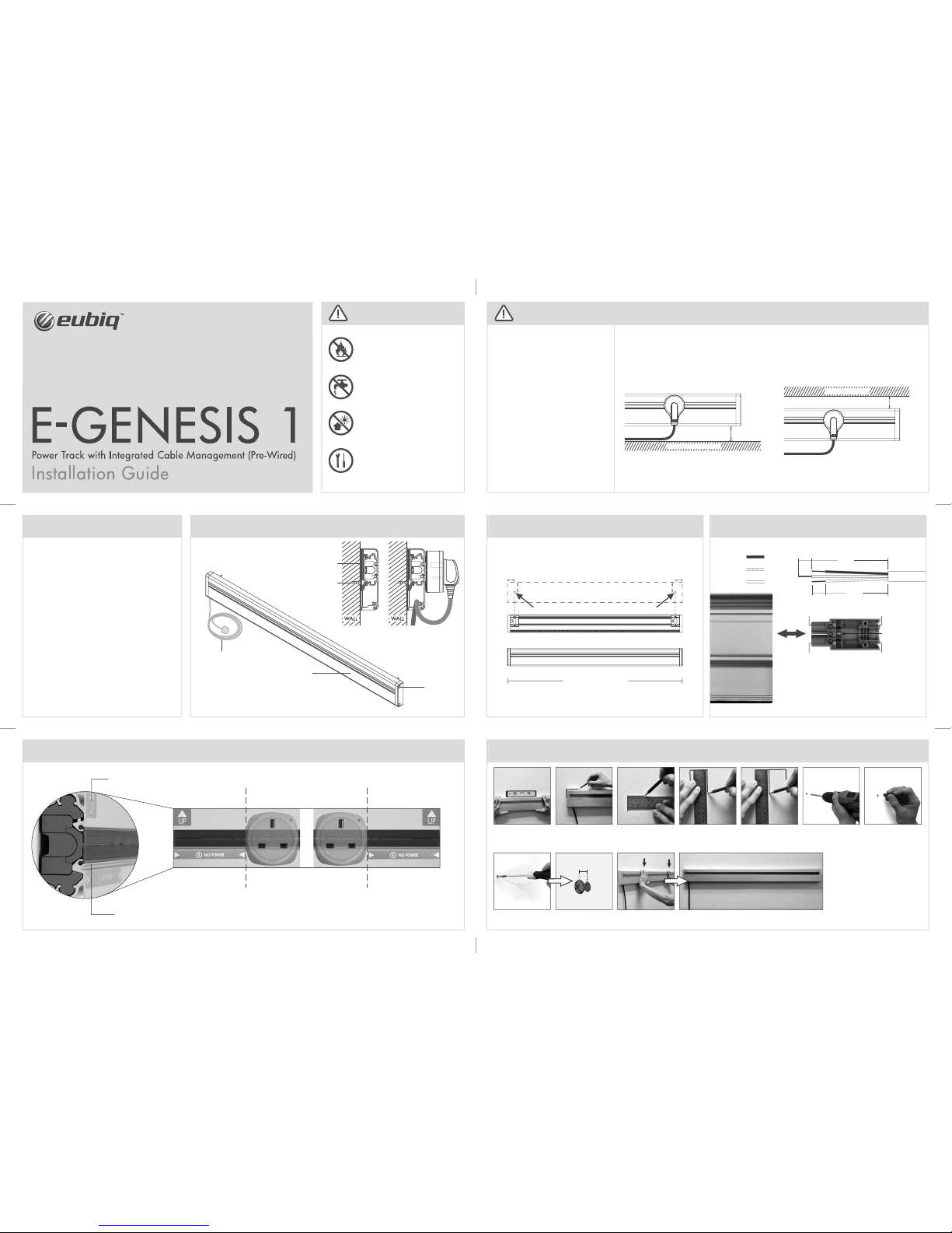
Installation of E-GENESIS 1
Drill holes based on both
markings on the wall.
Use Concrete drill bit Ø
5.5mm.
Measure 55mm from the
top of the track and do
marking for drilling.
Repeat step 3 and 4 on
the other end.
Measure 40mm from th e
side of the edge.
Mark out the guides on
both end.
Place the E-GENESIS 1 on
the wall and use a level
to ensure a horizontal
alignment.
Insert wall plugs into the
drilled holes. Use a mallet
if necessary.
2 5 6 7
DMK-005-024-01 ENG
1
Wiring Instructions
1) Do not perform in damp environment.
2) If in doubt, please consult a qualified electrician.
10mm
10mm
50mm
40mm
Live (Brown or Red)
Earth (Green or Green/Yellow)
Neutral (Blue or Black)
Prepare leads as shown:
Live Terminal
Earth Terminal
Neutral Terminal
Live Indicator
Neutral Indicator
Drilling Measurement
40mm
40mm
55mm55mm
Drill here
wall
Back View
Front View
Drill here
Drill on the circular markings using a 5.5mm concrete drill bit (not
included).
FIG. 3
Marking & Drilling Measurement Overview
Length of E-GENESIS 1
Technical Specifications
Rated Voltage : 250 V a.c. Single-phase
Rated Current : 13 / 16 Amp maximum
Frequency : 50Hz / 60Hz
Rated Impulse Withstand Voltage : 4000 V a.c.
Connection of Adaptor or Tap-off Unit : Intended to be connected and
disconnected when system is
energised and with a load
connected
Terminal Connecting Capacity
Live, Neutral & Earth : Rigid 2.5mm
2
to 6mm2
Flexible 1.25mm2 to 2.5mm
2
(16Amp)
Ambient Operating Temperature : -5
o
C to 45oC (not to exceed an
average of more than 35
o
C in
any 24 hours period)
Maximum Installation Altitude : 2000 meters
Resistance to Impact : Heavy Impact
Degree of Protection : IP4X
Degree of Pollution : 2 (Non-conductive pollution with
temporary conductivity caused
by condensation)
Track Material : Aluminum
Insulation Material : Polycarbonate
Dimension (Height x Depth) : 100mm x 28.5mm
Weight : Estimated 1.8kg (1000mm)
INSTALLING PARTY
All Power Tracks must be installed by a qualified
electrician.
USE OF EARTH LEAKAGE CIRCUIT BREAKER(ELCB)
It is a mandatory requirement that all installations
of electrical power source must be connected to an
ELCB to provide protection against overload, short
circuits and earth leakages faults. Failure to comply
can be hazardous.
INSTALLATION LOCATION
All Power Tracks must be installed at location that
complies with safety rules and regulations of
respective country.
INSTALLATION SURFACE
All Power Tracks must be installed on flat surface.
RECOMMENDED INSTALLATION CLEARANCE
Refer to FIG.1 & 2 on the right for more information
on the minimum clearance (from the floor or any
furniture fixtures) required for ‘twist-on’ adaptors
and accessories.
PLEASE READ BEFORE INSTALLING
Minimum Clearance for E-GENESIS 1 Installation
FIG. 1
Minimum clearance of 25mm from the bottom required.
FIG. 2
Minimum clearance of 20mm from the top required.
25mm
20mm
CEILING/CABINET
Product Orientation
V-GROOVE
‘UP’ Indicator
Adaptors are not to be
inserted within this region.
Adaptors are not to be
inserted within this region.
Product Overview
E-GENESIS 1
Pre-wired with 3m of
1.5mm² 3-core cable
Screw
Mounting Peg
Side View Side View with adaptor
Screw Cap
Keep away from fire.
Keep away from water.
Not for outdoor use.
To be installed by a
qualified electrician/
installer.
CAUTION
Align and hook the openings on the rear side of the E-GENESIS 1 with the screws on the wall.
Apply a downward force to secure the track.
2mm
8
Leave 2mm gap between
the screw head and the
wall surface for mounting.
9 10 11
Force
FLOOR/HOME FIXTURE
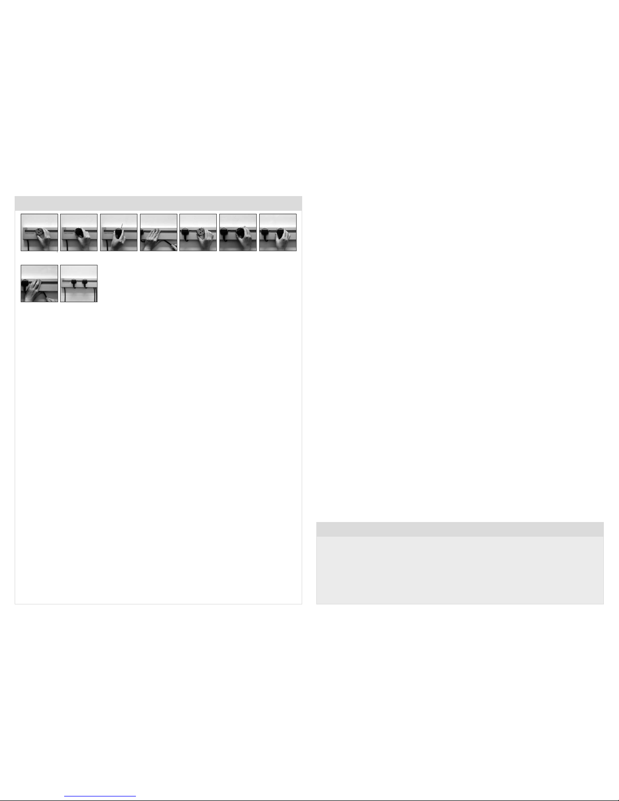
Cable Management
DMK-005-024-01 ENG
3 Years Limited Warranty
1. Eubiq Pte Ltd (”Eubiq”) warrants to the end-user of the product (”the Customer”) that the product will be free from defects in materials and
workmanship under normal use for a period of three (3) years from the date of retail purchase by the original end-user purchaser (”Warranty
Period”).
2. The Customer should access and refer to Eubiq’s website at www.eubiq.com for a list of Eubiq authorised dealers to contact for warranty service.
3. All requests for warranty service must be made within the Warranty Period, and be accompanied by the original dated proof of purchase.
ALL RIGHTS RESERVED. EUBIQ AND GSS ARE THE REGISTERED TRADEMARKS OF EUBIQ PTE LTD.
Tuck in excess length of
cable through the rubber
retainer.
With the LED indicator
lights up, the plug is now
switched on.
Insert plug and turn
adaptor fully upright.
(click sound)
Insert adaptor and turn 45
clockwise.
Repeat step 1.
Repeat step 4.
Repeat step 2. Repeat step 3.
End result, power with
cable management.
7
2 3 4 5 6 7
8 9
1
LED indicator
 Loading...