

Page 1

Installation, Operation and Maintenance
V SERIES Wallmount Air
Conditioners R410A
Series
REV. 10/26/16
1
678628-W
Page 2
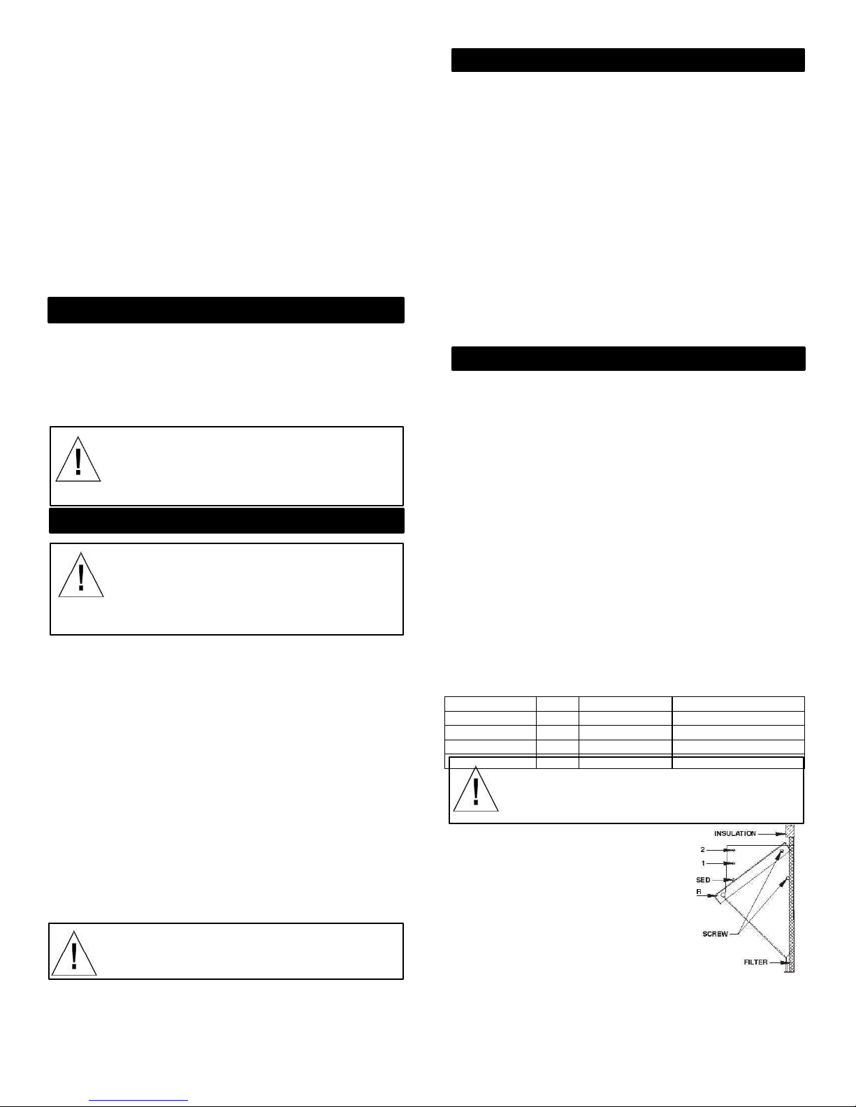
Your equipment is covered by a LIMITED WARRANTY against
UNIT M
ODEL QTY. FILTER SIZE TYPE 18,24,30,36 1 16 x 25 x 1 (st
andard) Disposable 18,24,30,36 1 16 x 25 x 2 (optional) Pleated 48, 60 1 20 x 30 x 1 (st
andard) Disposable 48, 60 1 20 x 30
x 2 (optional) Pleated
defects in material and workmanship.
This is a vertical, wallmount unit designed for many different
applications in both residential and commercial settings. It is selfcontained and arrives completely assembled, factory-charged and
wired. The unit is 100% run-tested at the factory to ensure proper
operation. Your unit is supplied with high-quality copper tubing and
enhanced aluminum-finned coils for high heat transfer efficiency
and long life. The unit cabinet is constructed of G-90 galvanized
steel. All exterior surfaces are finished with a baked-on polyester
coating. This will provide excellent corrosion protection in most
applications. However, if the unit is installed in an area with a
corrosive atmosphere, such as near an industrial plant or on the
seacoast, additional coating should be considered to extend the
life of the coils and cabinet.
This unit was designed for up to 105ºF of ambient temp
erature.
INSPECTION AND UNPACKING
A thorough inspection of the shipping container should be made
immediately upon receiving your unit. Look for any punctures or
openings. If it appears as if damage has occurred, it should be
noted on the freight bill before signing. The delivering carrier
should be contacted immediately to inspect damage, and no
installation work should begin until this inspection is completed.
OPERATING INSTRUCTIONS
If heating and cooling functions are controlled by separate
thermostats,
during the cooling season to prevent simultaneous operation of the
heating and cooling systems. Reverse the procedure during the
heating season.
If the same thermostat controls both heating and cooling
functions, set the thermostat to either HEAT or COOL as desired.
Set the desired temperature on your thermostat and set the fan
switch
(for air circulation only when the air conditioning system is
operating).
IMPORTANT: Wait at least three (3) minutes after turning the air
conditioner off before trying to restart. If an attempt is made to start
the compressor before the refrigerant pressures are equalized, the
compressor motor may trip on its overload. An additional waiting
period will be required before restarting.
turn the furnac
to “ON”
e
thermostat
(for
continuous air circulation) or to “AUTOMATIC
to the “OFF
”
position
MAINTENANCE
1. Always install and keep filters clean. Check filters every 2
weeks. Clean or replace if necessary. The factory-installed filter is
located behind the center front access panel.
”
DANGER: BEFORE PERFORMING ANY
WORK ON THIS EQUIPMENT, POWER SUPPLY
MUST BE TURNED OFF AT THE HOUSEHOLD
SHOCK, INJURY, DEATH, OR DAMAGE TO EQUIPMENT.
SERVICE BOX TO AVOID THE POSSIBILITY OF
SAFETY RULES
WARNING: FAILURE TO FOLLOW THESE
RULES AND INSTRUCTIONS COULD CAUSE A
MALFUNCION OR DESTRUCTION OF
PROPERTY DAMAGE, SERIOUS BODILY INJURY, OR
DEATH.
1. Installation and repair MUST be done by a qualified person.
2. AVOID ELECTRICAL SHOCK! Turn power OFF when
3.Close cover(s) before returning breaker(s)
4. Please observe good safety practices by wearing personal
5. Installation MUST conform to local codes. In the absence of
In our continuing effort to improve our product, specifications may
change without notice. If there are any questions, please see the
contact information on the last page of this manual.
In all cases, the equipment MUST be installed in accordance with
the installation instructions described in this manual.
EQUIPMENT WHICH COULD RESULT IN
he equipment should be inspected before use and at least
T
once annually by a professional service person.
servicing. There may be more than one disconnect switch
to de-energize unit.
protective equipment such as gloves and safety glasses to
avoid injury.
local codes, refer to the National Electrical Code (NEC),
ANS/NFPA No. 70-1993 and recommendations made by
the National Board of Fire Underwriters.
to “ON”
position.
WARNING: IMPROPER INSTALLATION MAY
AMAGE EQUIPMENT, CAN CREATE A HAZARD,
D
AND WILL VOID THE WARRANTY
REV. 10/26/16
TO CHANGE SYSTEM FILTER:
A. Turn the power to the unit off at the unit disconnect. The
disconnect is located on the front of the T Series unit
behind a small access door.
B. Remove the front center access door from the unit.
C. Remove and replace the filter with the type and size
indicated in the table below.
D. Replace the access door and turn on the power to the unit.
NOTE: If your system has a filter grille installed in the return air
opening, the unit filter should have been discarded during
installation.
The filter installed into the return air grille assemb
replaced with the same size and type provided with the grille.
If your system is equipped with a fresh air intake, the filter for the
fresh air assembly is accessed through the front center panel. The
filter is a permanent washable type.
WARNING: SERIOUS INJURY MAY RESULT IF
WATER SPRAY IS DIRECTED TOWARD LIVE
ELECTRICAL CONNECTIONS OR POWER
SOURCES.
TO CLEAN FRESH AIR INTAKE FILTER:
A. Follow steps A and B above.
“TO
CHANGE SYSTEM FILTER”.
B. Gently pull out the filter from the bottom.
C. Wash the filter with water.
D. Reinstall the filter, by sliding it into the
retaining rail.
E. Replace the access door and turn the
power on to the unit.
2. Keep the outdoor coil clean. Wash it
down with a garden hose if necessary.
2
ly should be
678628-W
Page 3

BE SURE THE UNIT DISCONNECT IS IN THE “OFF” POSITION
2.Locating the unit as close as possible to the main duc
t
3.
The clearance to combustibles is 0" on all sides, and 1/4
"
unit. Two-inch disposable filters can also be used and are
4.
The condenser air inlets (left, right and bottom inlets)
accommoda
te 2" filters. Th
e filter rack o
n th
is series i
s
5.
The condenser air outlet should be located at least 6’ awa
y
Maintenance section for the procedures for changing th
e
properly sized to allow a m
aximum velocity of 400 FP
M.
WHEN USING A FILTER GRILLE, THE FACTORY-INSTALLED
7.Service clearanc
e is 28" from th
e electrical box acces
s
center,
upper, an
d l
ower front access panels
.
8.The wall selected for unit installation MUST be able to or be
made to safely support the weight of the unit.
9.Do NOT locate where heat, lint or e
xhaust fumes w
ill b
e
discharged on the unit (as from dryer ven
ts)
.
AND THAT ALL ELECTRICAL POWER TO THE UNIT IS
TURNED OFF BEFORE CLEANING THE SYSTEM.
Remove any loose grass, leaves, papers, etc., from the area
around the condenser coil. These could reduce the air supply
through the coil and reduce the amount of cooling capacity.
3. Since the air conditioner is located outdoors, it is exposed to all
weather elements. Treat it with a good automobile paste wax
twice a year (in the spring and fall).
Check with your contractor if you have any questions regarding
the maintenance or operation of your unit.
INSTALLATION
. CODES
A
The installer SHALL comply with all local, state, and federal codes
and/or regulations pertaining to this type of equipment and its
installation. Such codes and/or regulations should take
precedence over any recommendations contained herein.
Installations SHALL be made in accordance with the National
Electrical Code, local codes, and recommendations made by the
National Board of Fire Underwriters.
B. UNIT SITE SELECTION
1. To eliminate noise from being transmitted into noise
sensitive areas, the unit should NOT be installed on walls
adjoining bedrooms, sleeping quarters, or adjacent to
windows.
system or area to be conditioned, will prevent lengthy duct
runs and unnecessary thermal and air-pressure losses.
for the first three (3) feet of supply duct.
SHALL be located at least 8" away from walls or other
obstructions for unrestricted airflow.
from any obstructions to prevent recirculation of condenser
air.
Bottom of the unit SHALL be located at least 12" away from
6.
the ground or other obstructions for unrestricted airflow.
5. R
eturn and supply grilles must be used when the return
and supply are not ducted. When a supply grille is used
in the installation, the louver spacing must be no greater
than 5/8 inch.
6. If the factory-installed filter is used on your installation,
access to the filter is made through the center panel on the
front of the unit.
IF A REMOTE FILTER IS USED, SUCH AS A FILTER GRILLE,
THE FACTORY-INSTALLED FILTER MUST BE REMOVED AND
DISCARDED.
D. DUCTWORK
1. Properly-sized duct systems are critical for satisfactory
operation of any air conditioning system. All ductwork
MUST be correctly sized for the design air flow requirement
of the equipment.
2. The recommended operation duct static is to deduct 0.07"
W.C. for any size of heater 5 kW to 20 kW on factory or
field-installed heaters.
3. Ductwork routed through wall cavities, as well as any duct
not in conditioned space, MUST be insulated. Supply
ducting routed through exterior walls MUST be insulated
with 1" insulation to the back of the unit.
4. Supply and return air ducts should be flush with the exterior
wall and sized to fit over the unit duct collars in order to
compress the collar air gasket.
5. If supply duct is flashed to the exterior of a building
onstructed with combustible material, the flashing MUST
c
be insulated in order to maintain the required clearances
to combustible materials. Required clearance is 1/4" for
the first three (3) feet of supply duct.
E. FILTERS
1. One-inch disposable filters are supplied standard in each
available as an option. The filter rack is adjustable to
adapted by bending the retaining brackets. Refer to the
filters.
If a filter grille is used in the installation, the filter should be
2.
FILTER MUST BE REMOVED.
panel located on the front of the unit and 28" from the
C. UNIT PREPARATION
1. The V Series model units have top rain flashing built onto
the unit. The bottom-mounting flange for all models is
shipped
Installation”
flange.)
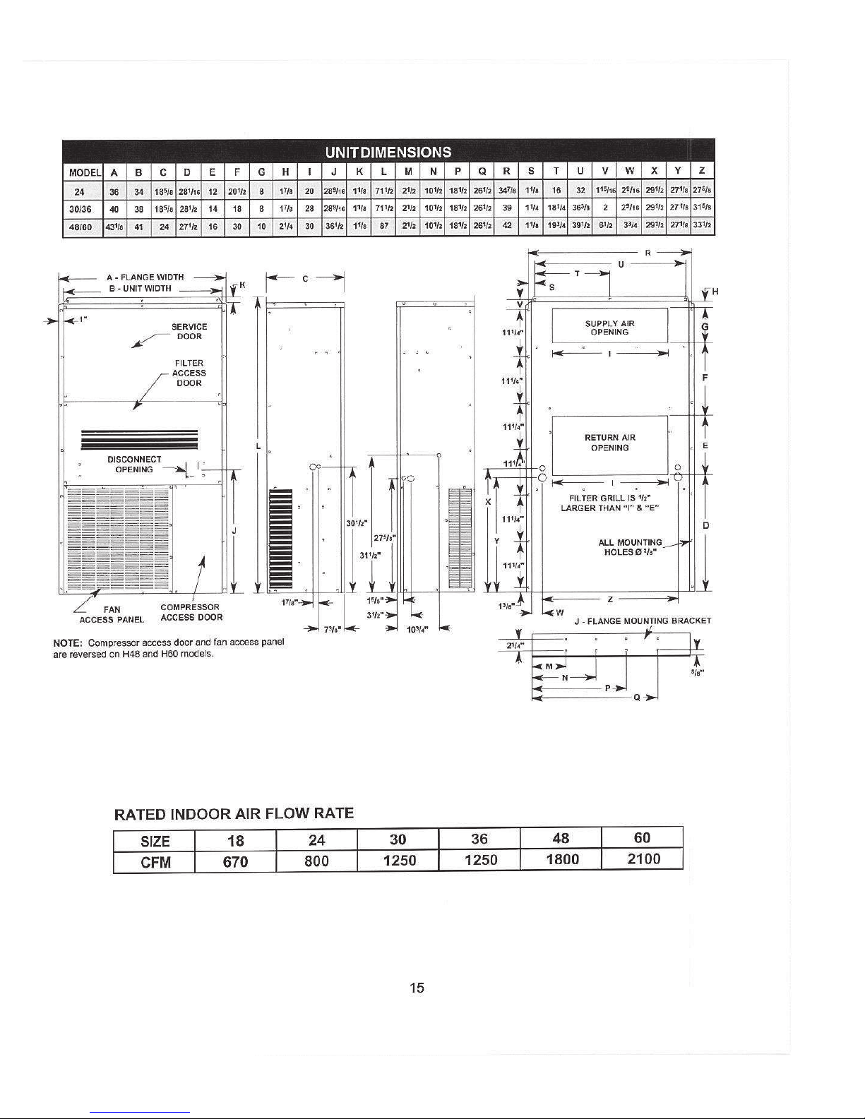
2. Electrical entrances are located on the right side, left side,
and back of all V Series units. Refe
Electrical Hook-up” for details
3. Bend the lids of return and supply opening to form return
and supply air collars and install air gaskets.
4. The supply and return air ducts should be checked to be
sure they:
a. Match the openings on the unit to be installed.
b. Have the same distance between them vertically as
separately and in place
for
the
recommended use
the openings on the unit to be installed.
. (Refe
.
REV. 10/26/16
r to “Secti
r to “Section H.
on
of
the bottom
J. Uni
F. ELECTRICAL POWER
The installer MUST check available power to make certain it
matches the unit nameplate rating and that constant voltage can
be maintained to the unit. Unsatisfactory and unsafe performance
could otherwise result. The local power company should be
contacted about questions concerning power supply.
G. BREAKER/DISCONNECT ASSEMBLY
These units are standard equipped from the factory with a unit
t
disconnect. This is in the form of a circuit breaker (230V models)
or disconnect (460V models). If an optional electric heat kit is to be
installed, follow the instructions included with the heater assembly.
See Figure 1 for reference.
3
678628-W
Page 4
WARNING: ELECTRICAL EQUIPMENT
Wire Gauge Maximum Length 20
45' 18 60' 16 100' 14 160' 12 250'
SHOULD BE INSTALLED BY A QUALIFIED,
LICENSED ELECTRICIAN. IMPROPER
EQUIPMENT, CAN CREATE A HAZARD AND WILL VOID
WARRANTY.
ELECTRICAL HOOK-UP MAY DAMAGE
H. ELECTRICAL HOOKUP
The line voltage electrical service can be routed through the right
side panel, the right side of the back panel, or left side panel. Each
area is supplied with two line voltage knock-outs (1/2" – 3/4" and
1" – 1¼"). Low voltage wiring can be routed through the right or left
side panel.
NOTE: When ro
compartment, conduit MUST be used (even though this is a dry
area) to comply with the NEC code. A 11/4" conduit is supplied
for this application. Refer to the ELECTRICAL DATA tables for
minimum wire size and maximum breaker size. All wire sizes listed
under the dual-feed circuit column are based on no more than
three (3) conductors in the same conduit. If two circuits or more
than three (3) conductors are to be routed in the same conduit, the
ampacity of the wire size listed MUST be derated. Refer to Article
310 of the NEC code for adjustment factors. Be sure to install a
ground wire of the proper size
uting line voltage through the return air
to the unit’s equipmen
t ground lug.
condition for which it will be used. For example, a unit to be
installed on a building that is intended to be transported will
require more wall strength than a unit installed at a
permanent site. Existing walls may need additional
reinforcement. NEVER RELY ON EXTERIOR SIDING OR
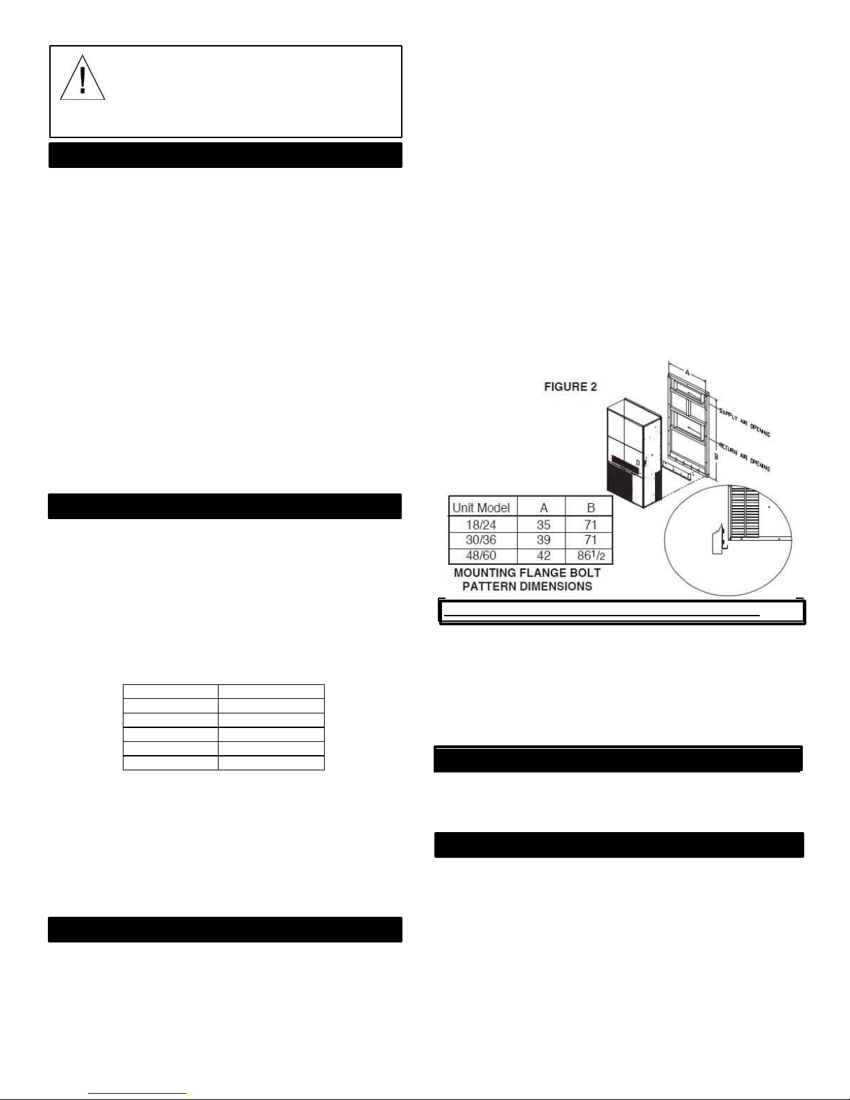
PLYWOOD TO SUPPORT THE UNIT. Figure 2 at right
represents a typical installation of a single-story stud wall at
a permanent site. Since building materials and techniques
vary with regions and intended use, a building contractor
and/or local building code official MUST be consulted for
suitable construction methods.
2. Locate and attach the lower mounting bracket in the
desired location on the building.
3. Apply a suitable amount of caulk or silicone across the
entire length of the top rain flashing and side mounting
flanges.
4. Remove the flanges on both ends of the pallet and slide the
unit approximately 2” off
into location with fork truck, taking care to align unit with
lower mounting bracket.
5. While allowing a small portion of weight on the lower
bracket, push the unit against the wall and fasten
appropriately.
the rear
of
pallet. Lift unit gently
I. LOW VOLTAGE WIRING
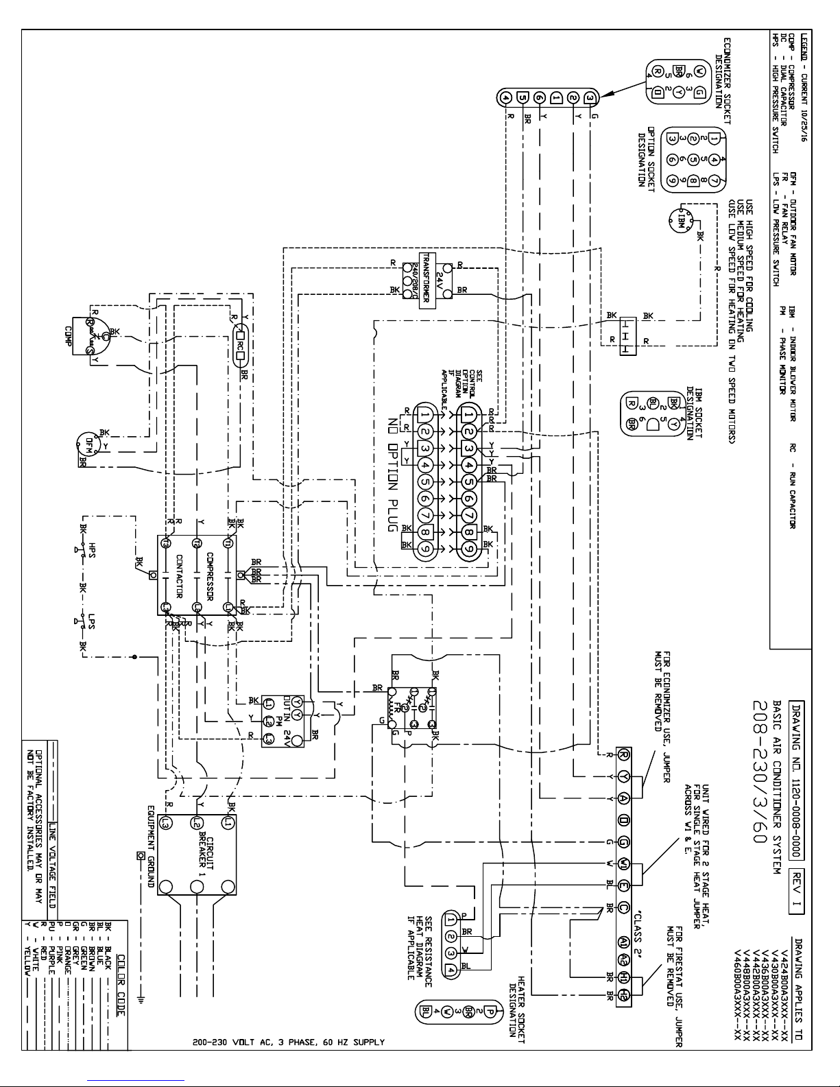
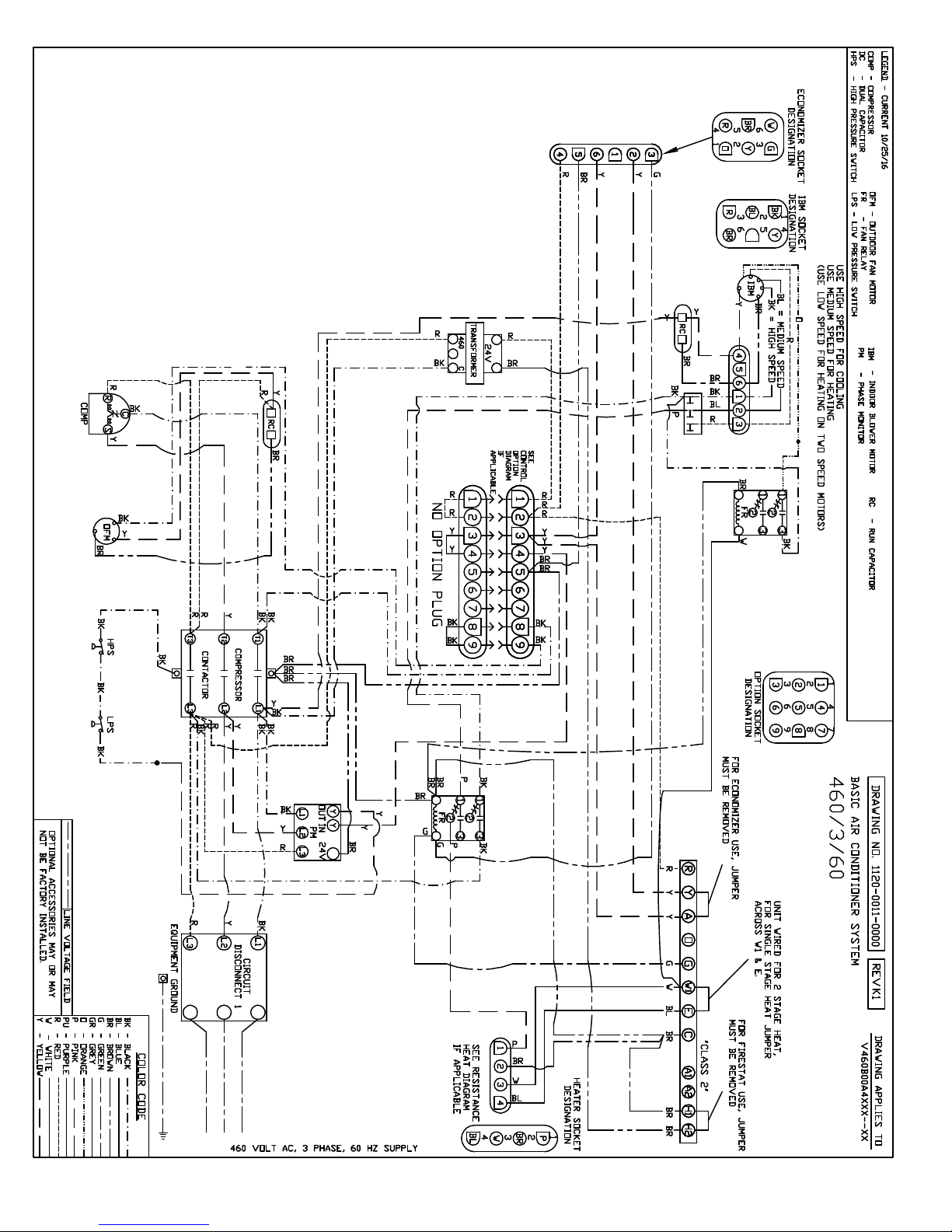
230 volt, 1- and 3-phase units are equipped with dual-primary
voltage transformers for 208/240 volt operation. These models are
factory wired to the 240 volt tap. For 208 volt operation connect the
factory-installed black wires from the 240 volt tap to the 208 volt
tap. The acceptable voltage range of the tap is as follows.
Five (5) conductor thermostat wires should be run from the
thermostat location to the unit. Thermostat wire should be sized as
shown on the table below.
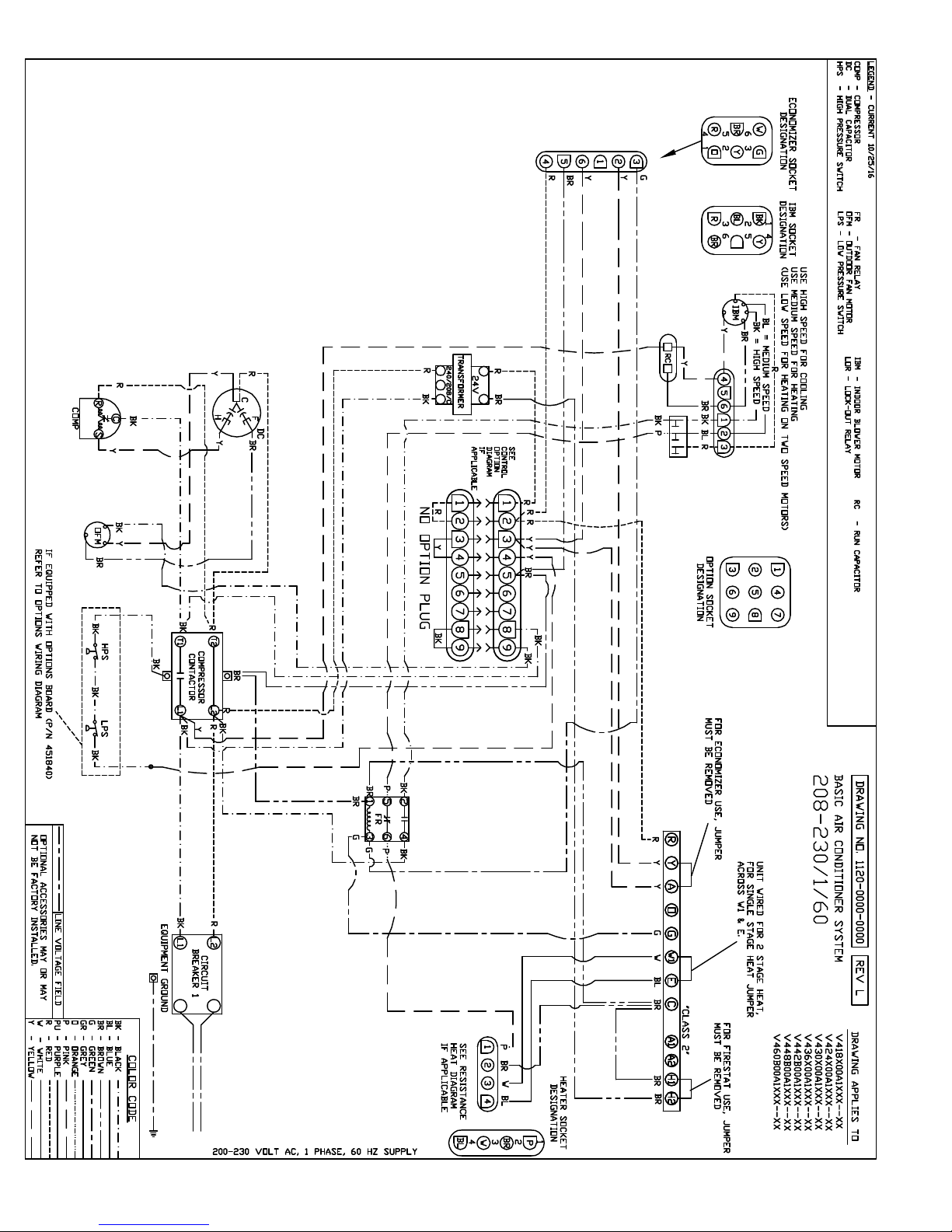
Refer to wiring diagrams for connection details.
Tap Voltage Range
240 Volt 253 - 216
208 Volt 220 - 187
STAGING OF ELECTRIC HEAT
All V Series units with electric heat assemblies above 10 kW may
be wired for single or two-stage heat. These models come factory
wired for single-stage operation. For two-stage operation, remove
the jumper bar from between the W1 and E terminal. Wire the firststage heat to terminal W1. Wire the second-stage heat to terminal
E.
J. UNIT INSTALLATION
V SERIES UNITS ARE FOR USE IN SINGLE-STORY
NGS ONLY
BUILDI
1. As previously stated, the wall that the unit is to be installed
onto MUST be strong enough to support the unit under the
REV. 10/26/16
SPECIAL NOTES FOR UNIT INSTALLATION
1) Minimum 12” clearance at the bottom of the unit for
unrestricted airflow.
2)
Ensure the ambient temperature uniformity around unit
3)
Intake and discharge of the outdoor air flow must not be
restricted or altered.
4)
All insulation and sealing related to the installation must
be completed properly
5) External Static pressure should not exceed the minimum
value in the AHRI Standard 390
K. CONDENSATE DRAIN
A 3/4” drain hose is located on the bottom side of
drain may be extended for condensate removal to comply with
local codes (use fitting size or larger). Install a condensate trap on
this line.
L. AVAILABLE OPTIONS
Eubank wallmount air conditioners and heat pumps have the
ability to equip a variety of options:
Electric Heat 5-20kW Energy
Recovery Ventilator Sound
Attenuation Module Powered
Ventilation Damper
Low Ambient Packages
Economizer
Lead Lag Controllers
Option kits must be installed according to the respective
installation manual to ensure safe and reliable operation.
Installation manuals are included with the option kit or can be
4
found on the Eubank website, www.EubankNCC.com.
the unit. The
678628-W
Page 5
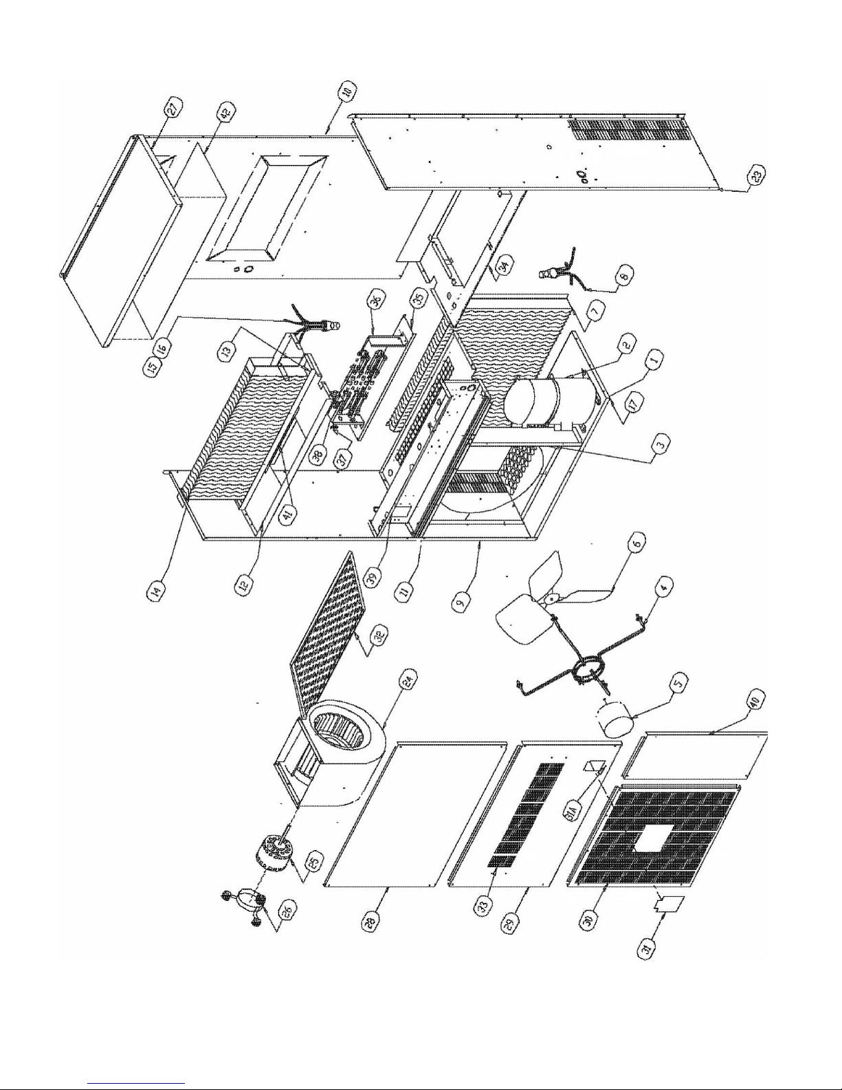
EXPLODED PA ATS DRAWi NG - 18 / 24 / 30 / 36
REV. 10/26/16
5
678628-W
Page 6
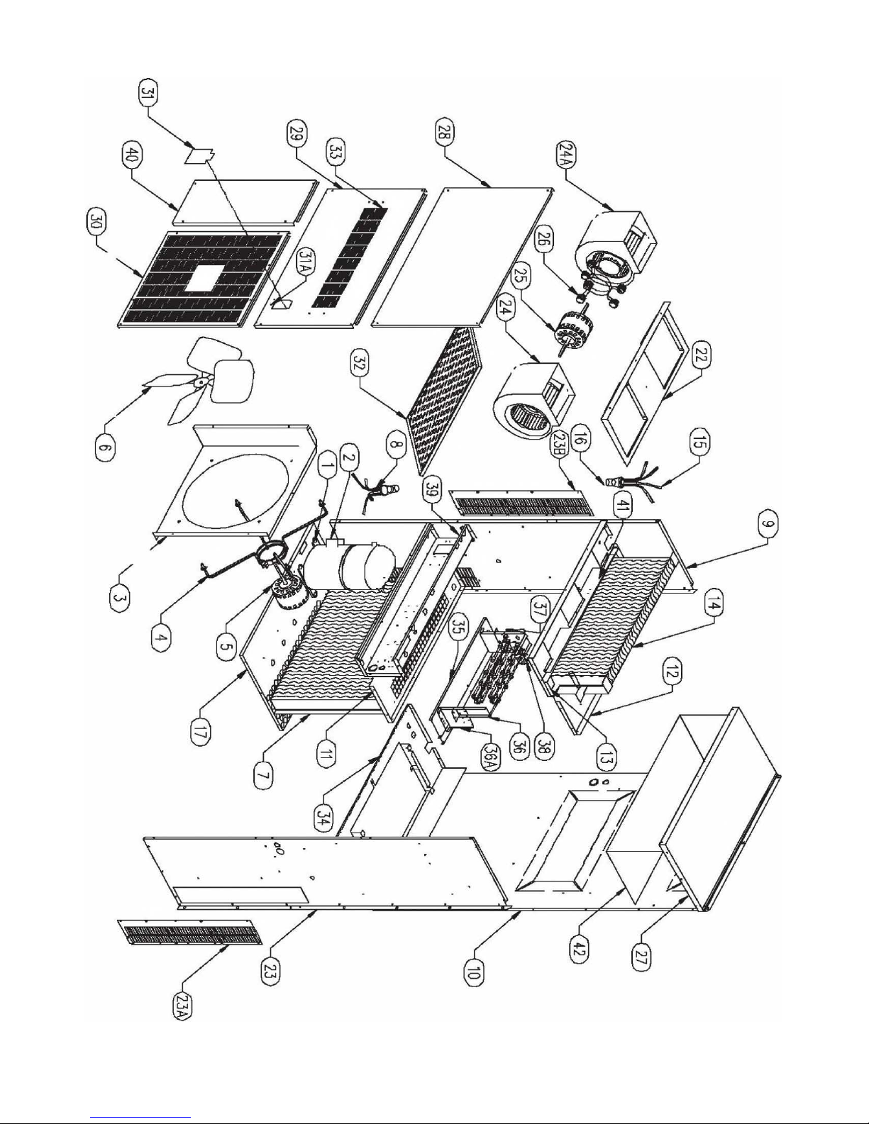
EXPLODED PARTS DRAWING -
48/60
REV. 10/26/16
6
678628-W
Page 7
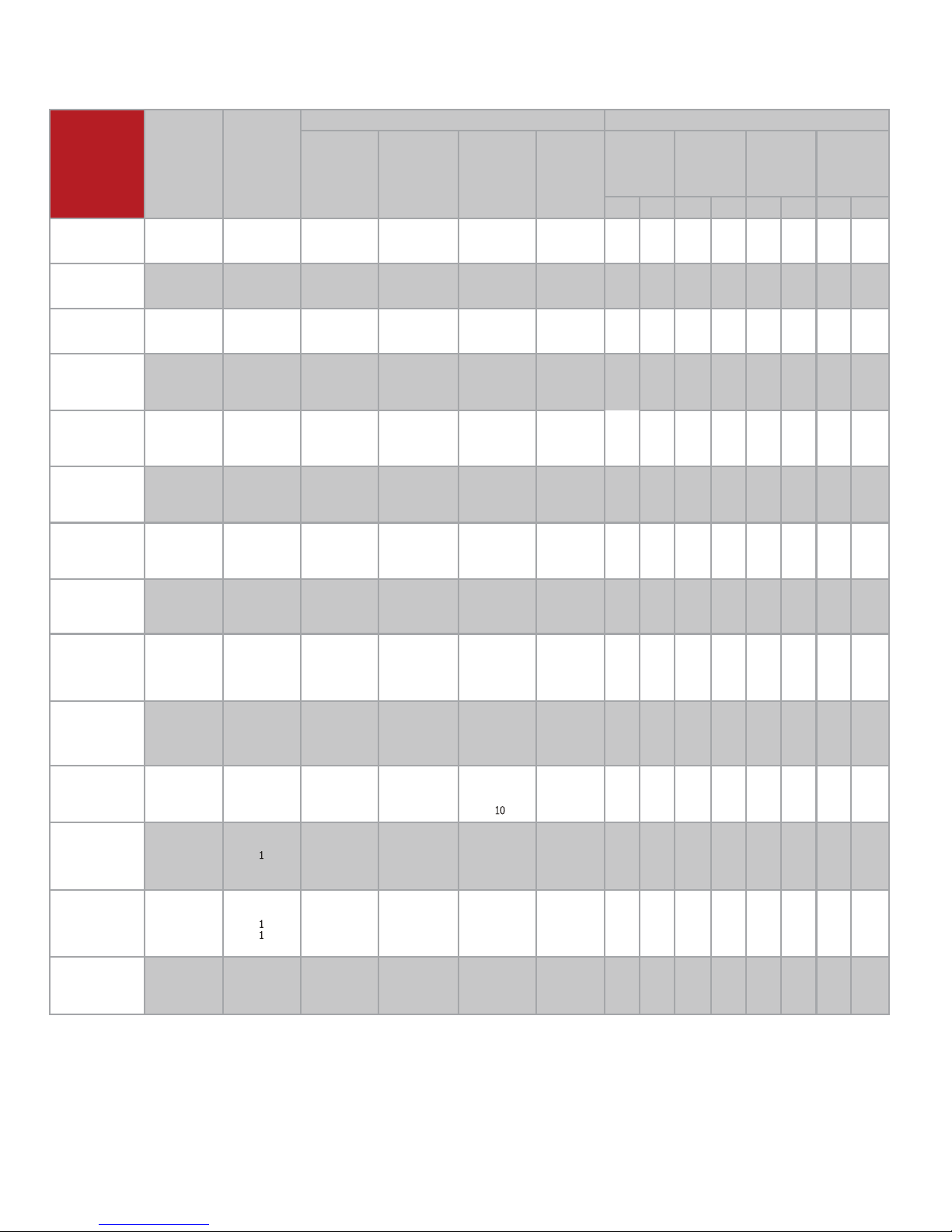
V Series AC Electrical Data
MODEL NO.
HEATER kW
[1]
VOLT/
PHAS
E 60
Hz
NO. OF
FIELD
CKTS.
SINGLE-FIELD CIRCUIT DUAL-FIELD CIRCUIT
FIELD
POWER
WIRE SIZE
CKT1 CKT2 CKT1 CKT2 CKT1 CKT2 CKT1
CKT2
V418B00A
10
208-230/1
1
1
1
30
60
14
10
6
14
10
10
V424B00A
208-230/1
1
1
1
30
30
60
14
10
6
10
10
V424B00A
208-230/3
1
1
1
208-230/1
1
1
1
24
12
10
6
10
10
V430B00A
208-230/3
1
1
1
30
14
12
10
10
V436B00A
10
15
208-230/1
1
1
1
26
60
10
10
6
10
10
10
26 52 30 60 10 6 10
10
V436B00A
9
15
208/230/3
1
1
1
1
20
30
30
12
12
10
8
10
V436B00A
9
15
460/3
1
1
1
1
10
15
15
30
14
14
14
14
14
V448B00A
10
15
60
10
10
10
10
10
52 30 60 10 6 10 10
V448B00A
9
15
18
208-230/3
1
1
1
1
1
24
24
30
30
60
12
12
10
6
10
10
V448B00A
9
15
460/3
1
1
1
1
15
15
14
14
14
14
14
10
V460B00B
10
15
208-230/1
1
1
60
60
60
8
8
6
10
10
10
52
60 10 6
10 10
V460B00B
9
15
18
208-230/3
1
1
1
50
60
10
10
10
6
6
10
10
10
10
V460B00B
9
15
460/3
1
1
1
1
30
14
14
14
10
10
& ELECTRIC
5
5
10
6
9
V430B00A
5
10
POWER
MCA
14
29
55
19
29
55
13
20
30
30
56
MOP
[2]
40
20
20
25
40
40
60
FIELD POWER
WIRE
SIZE
[3]
14
12
10
GROUND
WIRE
SIZE
[3]
10
12
10
10
10
MCA
MOP
[2]
[3]
GROUND
WIRE
SIZE
[2]
6
9
5
6
6
5
6
6
5
208-230/1
2
2
1
1
1
2
17
22
56
22
49
16
33
33
58
33
50
60
10
13
17
39
39
58
30
10
25
26
25
25
40
40
40
30
40
50
20
50
50
40
70
20
30
10
6
6
10
10
10
10
10
12
10
10
10
8
12
27
33
40
6
6
26
26
33
60
13
13
17
26
40
40
40
70
20
20
20
8
12
12
12
7
Page 8
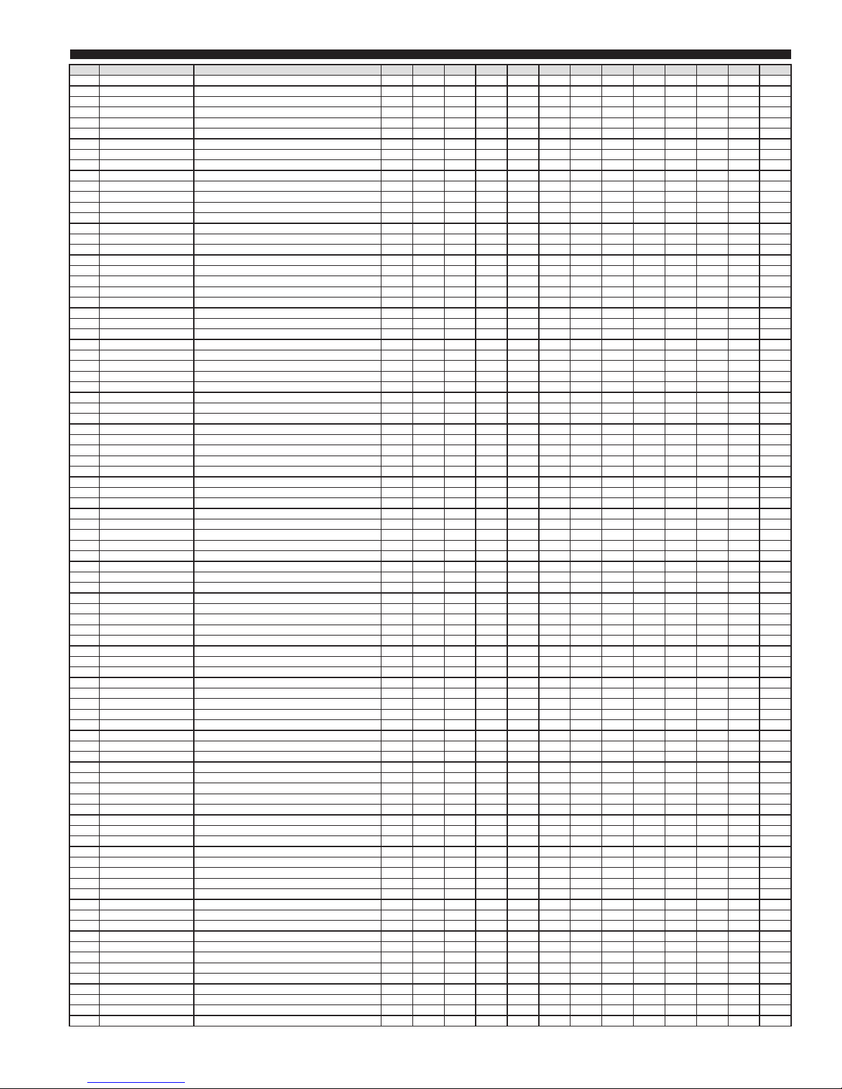
PART NUMBER DESCRIPTION V418B1 V424B1 V430B1 V430B3 V436B1 V436B3 V436B4 V448B1 V448B3 V448B4 V460B1 V460B3 V460B4
2 COMP-L18-001 H62J18BABCA
2 COMP-L24-001 H82J24BABCA
2 COMP-L30-001 H82J28BABCA
2 COMP-L36-001 H82J35BABCA
2 COMP-BZP16-001 ZP16K5EPFV130 X
2 COMP-BZP24-001 ZP24K5EPFV130 X
2 COMP-BZP28-001 ZP28K5EPFV130 X
2 COMP-BZP28-003 ZP28K5ETF5130 X
2 COMP-BZP34-001 ZP34K5EPFV130 X
2 COMP-BZP34-003 ZP34K5ETF5130 X
2 COMP-BZP34-004 ZP34K5ETFD130 X
2 COMP-BZP44-001 ZP44K5EPFV130 X
2 COMP-BZP44-003 ZP44K5ETF5130 X
2 COMP-BZP44-004 ZP44K5ETFD130 X
2 COMP-BZP54-001 ZP57K5EPFV130 X
2 COMP-BZP54-003 ZP57K5ETF5130 X
2 COMP-BZP54-004 ZP57K5ETFD130 X
7 COND- V424 COND COIL X X
7 COND- V436 COND COIL X X X X X
7 COND- V460 COND COIL X X X X X X
8 550510 FLOWRATOR 4 CIRCUIT-COND X
8 550505 FLOWRATOR 3 CIRCUIT-COND X X X X X X
8 550517 FLOWRATOR 6 CIRCUIT-COND X X X X X X
14 EVAP-VH424 EVAP COIL X X
14 EVAP-VH436 EVAP COIL X X X X X
14 EVAP-VH460 EVAP COIL X X X X X X
15 550510 FLOWRATOR 4 CIRCUIT-EVAP X
15 550517 FLOWRATOR 6 CIRCUIT-EVAP X X X X X X
15 550521 FLOWRATOR 9 CIRCUIT-EVAP X X X X X X
550536 RESTRICTOR .063 X X
550531 RESTRICTOR .065 X X
550538 RESTRICTOR .070 X X X
550550 RESTRICTOR .094 X X X
550548 RESTRICTOR .096 X X X
061507 FILTER DRIER X X X X X X X
061508 FILTER DRIER X X X X X X
3 2021-5008 FAN SHROUD V18-24 X X
3 2022-5008 FAN SHROUD V30-36 X X X X X
3 2023-5008 FAN SHROUD V48-60 X X X X X X
4 259108 MOTOR MOUNT CONDENSER FAN X X X X X X X
4 259109 MOTOR MOUNT CONDENSER FAN X X X X X X
5 0250-0025 MOTOR CONDENSER 230V 1/5 HP X X X X X X
5 351145 MOTOR CONDENSER 230V 1/2 HP X X X X
5 359100 MOTOR CONDENSER 460V 1/4 HP X
5 351146 MOTOR CONDENSER 460V 1/2 HP X X
6 0550-0009 FAN BLADE 20" V18-36 X X X X X X X
6 259114 FAN BLADE 22" V48-60 X X X X X X
9 2022-5000 ASSEMBLY LEFT SIDE PANEL V18-36 X X X X X X X
9 2023-5000 ASSEMBLY LEFT SIDE PANEL V48-60 X X X X X X
10 2021-5012 ASSEMBLY REAR PANEL V18-24 X X
10 2022-5012 ASSEMBLY REAR PANEL V30-36 X X X X X
10 2023-5012 ASSEMBLY REAR PANEL V48-60 X X X X X X
11 2021-5003 ASSEMBLY DIVIDER DECK V18-24 X X
11 2022-5003 ASSEMBLY DIVIDER DECK V30-36 X X X X X
11 2023-5003 ASSEMBLY DIVIDER DECK V48-60 X X X X X X
12 2021-5005 ASSEMBLY BLOWER PAN V18-24 X X
12 2022-5005 ASSEMBLY BLOWER PAN V30-36 X X X X X
12 2023-5005 ASSEMBLY BLOWER PAN V48-60 X X X X X X
13 2021-0006P ASSEMBLY DRAIN PAN V18-24 X X
13 2022-0006P ASSEMBLY DRAIN PAN V30-36 X X X X X
13 2023-5006 ASSEMBLY DRAIN PAN V48-60 X X X X X X
17
2021-5002 BASE PAN ASSEMBLY V18-24 X X
17 2022-5002 BASE PAN ASSEMBLY V30-36 X X X X X
17 2023-5002H BASE PAN ASSEMBLY V48-40 X X X X X X
22 2021-5018 BLOWER MNTG TRAY V18-24 X X
22 2022-5018 BLOWER MNTG TRAY V30-36 X X X X X
22 2023-5018-4 BLOW ER MNTG TRAY V48 X X X
22 2023-5018-5 BLOW ER MNTG TRAY V60 X X X
23 2022-5001 ASSEMBLY RIGHT SIDE V18-36 X X X X X X X
23 2023-5001 ASSEMBLY RIGHT SIDE V48-60 X X X X X X
23A 2023-5088 GRILL INLET RIGHT SIDE V48-60 X X X X X X
23B 2023-5089 GRILL INLET LEFT SIDE V48-60 X X X X X X
24 194700050002 BLOWER 9-7R DD 18, 24, & 48 CW RIGHT X X X X X
24 194700050004 BLOWER 10-7R DD 60 CW RIGHT X X X
24 0500-0010 BLOWER 10-10 DD 30 & 36 X X X X X
24A 1947000050001 BLOWER 9-7L DD 48 CCW LEFT X X X
24A 194700050003 BLOWER 10-7L DD 60 CCW LEFT X X X
25 351115 MOTOR BLOWER 1/6 HP 230V X X
25 194090000006 MOTOR BLOWER 1/3 HP 230V X X X X
25 020008 MOTOR BLOWER 1/2 HP double shaft 230V X X
25 351424 MOTOR BLOWER 3/4 HP double shaft 230V X X
25 359101 MOTOR BLOWER 1/3 HP 460V (2-3 ton) X
25 020005 MOTOR BLOWER 1/2 HP double shaft 460V X
25 351426 MOTOR BLOWER 3/4 HP double shaft 460V X
26 BLWR-MTG2B MOTOR MOUNT INDOOR ASSY V18-24 X X
26 258972 MOTOR MOUNT INDOOR ASSY V30-36 X X X X X
26 258976 MOTOR MOUNT INDOOR ASSY V48-60 X X X X X X
27 2021-5007 TOP V18-24 X X
27 2022-5007 TOP V30-36 X X X X X
27 2023-5007 TOP V48-60 X X X X X X
REPLACEMENT PARTS LIST - V SERIES WALLMOUNT A/C
8
Page 9
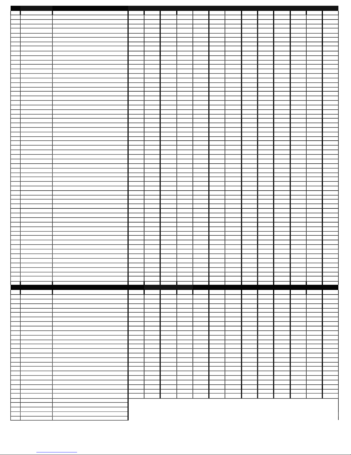
28 2021-5
010 TOP FRONT P
ANEL VlB-24
x
29 2021-5
011 TOP FR
ONT PANEL VtB-2
5
28 2023-5010
xxxxx
x
29 2021-5
011
MIDDLE F
RONT PANEL
(no fre!h
aw) VIB-2
4
x
x
x x
29
MIDDLEfRO
NT PANEL
(baromet
ricf
/a)
VIB-24
x
x
2
9 2
022-5
011
{no fre!h airl
xxx
x x
)( )(
x x
(baromet
ricf/a)
x
x
x
x
xxxx xx
(economi
zor f/a)
xxx
x
x
x
29
2023-50 ll
F
MIDDLE FRONT PANEL
(barometric I/al
V48-
60
xxx
x x
x
30 2021-5014 LOWER
CONDENSER PANEL V18-
24
x
x
xxx
3
0
x
31 2022-5062
xxxxx
x
x
x
xxx
xxxxx
x
x
x x
x
32 659942 AJR
FILTER DISPOSABLE
16"2Sxl VlB-
36
x
xxx
xxx
x
x
x
32 659926
x
x
x
3
2
x
xxx
x
x
x
x
xxxxxxxxxxx
34
x
34
2
022-5004
FILTER RAO(
V30·36
x
x
x
34
2023-5004
FILTER RAO( V48-6
0
x
xxx
3
5 2022-5
021 HEATER MOUNTING PLATE VlB-3
6
xxxxxxx
xxx
x x
x
36
x
xxxx
36 0430-007
4 H
EATER 5KW IP 240V
xxxxx
x
3
6 EGAIOBI-AC
FIELD I
NSTAil H
EAT KIT I
OKW I PHASE 230
V 36 0430
.oon HEATER lOKW IP 240
V x
xxx
x
x
36 EGHISBI-AC FIELDINSTAlLHEAT
K
IT ISKWl
PHASE230
V
xxxxx
x
36 0430-0074 HEATER
5KW IP 240
V
xxx
36 0430
.oon
xxx
xxx
x
xxx
36
EGH
11B3..AC
FIELD INST
All HEAT KIT IIKW3 PHASE
230
V
xxx
x
36 4
58011 HEATER llKW 3P 24
0V
x
x
x
3
6 EGH
11!83
..A
C
x
x
x
x
x
x
xxx
36 4
580
15
HEATER 6KW 3P 460
V
x
x
x
36 EGH11D4-AC FIELD INSTALL HEAT KIT II
KW3 PH
ASE460V
xxx
36 458017 H
EATER llKW 3P 460
V
xxx
36 EGH1504-AC FIELD INST
ALL HEAT KIT 15KW3 PH
ASE460
V
xxx
36 4
58020
xxx
x
xxxxx
x
xxx
x
x
xxxxxxxxxxxxx
3
8
4
54323 S
WITCH LIM
IT 160-30F 240 W
/fUSE
xxx
x
x
xxxxxxx
x
39 2021·5009H eox CONT
ROL VIS-24 x
x
x
x
x
x
x
x
x
xxx
x
4
1
2021-50
20
BLOWER
OJT OFF SHIELD VlB-2
4
x
x
2
022-50
20 BLOWER OJT OFF
SHIELD V30-3
6
x
4
1 2023-5020-4 BLOWER OUT
OFF SHIELD V48
)(
x
x
)(
)(
)( )( )( )( )( )( )( )( )(
xxx
x
x
x
x
x
4
50362 COMP
CAPAOTOR 7
.S/35@37
0
0400-003
1 COMP
CAPAOTOR 1
0/80@37
0 x 450368
45036
4 COMP CAPAOT
OR 7.5/40@44
0
450
361 COMP
CAPAOTOR 7.5/30@370
x
x
x
x
45020
5 BLWR
CAPAOTOR 7.5@
370 x
xxx
x
1605007
30145 BLWR
CAPAOTOR 7
.5@440
x
x
x
xxx x
x
4527
52 TRANSFORMER
208/240V50VA 2
4V
45275
6 T
RANS
FORMER 480V SOVA 24V
4522
00
FAN RELAY
082 lN-
00 81A FAN RELA
Y
xxx
x
45380
7 ORCUIT BR
EAKER 3 POLE 3P 60 AM
P
xxx
4
51956 OISCONNECf KN08 460V
x
x
x x x x x x x x x
451049 JUMPER BAR AS
SEMB
LY
OPTIONAL
451810 CPTION S
ao.R
D
OPTIONAL
454388 LOW
PRESSUR
E
SWITOi
STANDARD ON All UNITS
4
51992
OPTIONAL
29 2021-5011E
202
1-5011F
29
29
29
30
31A
32
35 65SM1007.f
36 EGH06B3..AC FIELDINSTAlL HEAT KIT6KW3
36
36
36
37
37
38
39 2022-500911
39 2023-5009H
40
40
40
41
41
2022.50 uF
2023-5
011
2023-5011
E
2022-5014
2023-5014 LOWER CONDENSER PANEL V48-60
7
0518
659943
659924
654602 ALUMINUM FILTER Sx30x.025 VI
2021-50
04 FILTER RAO( VlB-24
EGA05BI-AC FIELD
4
58009
HEATER 6KW 3P
4
58013
EGH0604
-AC FIELD INSTAil HEAT KIT 6KW3 PHASE 460V
2022-HEP
L HEATER
2023-HEP
L
4
54332
SWITCH llM
2021-5017
2022-5017
2023-5017
2023-5020-5
BLOWER OUT OFF SHIELD V60
TOPFRONTPANELV
MIDDLE FRONT PANEL
MIDDLE
FRONT PANEL
MIDDLE FR
ONT PANEL
MIDDLE
FRONT PANEL
MIDDLE FRONT PANEL
LOWER CONDENSER PANEL
DISCONNECT
BREAXER
AIR
FILTER
AJR
FILTER DISPOSABLE
AJR
FILTER
HEATER MOUNTING PLATE V48
INSTAll
FIELD
INSTAll HEAT KIT 18KW 3 PHASE 230V
HEATER EXTENSION PLATE H48
COMPRESSOR A
C
OMPRESSOR A
COMPRESSOR A
(economizer I/a)
(no fre!h alt)
ACCESS
DOOR LATOi VI
DISPOSABLE 16"2Sx2 VlB-3
DISPOSABLE
HEAT KIT 5KW I PHASE 23
HEATER IOKW IP
HEATER 18KW 3P 240V
HEATER 15KW 3P
EXTENSION
IT
245F ONE SHOT
eox
CONTROL
eox
CONTROL V48-60
CCESS
CCESS
CCESS
48-60
V30-36
V
V30-36
DOOR VlB-60
B-60
20.30.1 V4
20.30.2 V48-6
B-60
-60
240V
PHASE
240V
460V
PLATE H24-36
-60
V30-36
DOOR Vl
S-24
DOOR
V30
·36
DOOR V48-60
VIS-24
V30·
48-60
V48
8-6
230
)(
)(
)(
36
-60
6
0
0
0V
V
)(
)(
)(
x
)(
)(
x
)(
)(
)(
)(
)(
)(
)(
)(
x
)(
)(
)(
)(
)(
)(
)(
)(
)(
)(
)(
)(
)(
)(
)(
)(
)(
)(
)(
)(
x
)(
x
)(
)(
)(
)(
)(
)(
)(
)(
)(
x
453150
453
770
453
772
452
812
COMP
450370
COMP CAP
450378
COMP CAPAOTOR 10fl0@370
4
50325
4
51000
42004
45
1955 DISCONNECf KIT 460V
0415
-0028 LOW VOLTAGE TERMIN
451988 HIGH
COMP
CONTACTOR
COMPCONTAcrOR2P
COMP
CON
BLWR CAPAOTOR
OROJIT BREAKER 2 POLE IP 60 AMP 240V
1 POlf !P
Olf
T AcrOR 3 POlf 3P 25
PHASE MONIT
CAPAOTOR 7.5/40@
TERMINAL Bl.CCX
FAN
IP40AM
OR
AOTOR
7.5/45@3
10@370
AL BOARD
PRESSURE SWIT
CYQ.E SWI
TCH
25AMP
CH
370
AMP
70
REV. 10/26/16
)(
P
x
)(
)(
)(
)(
)(
)(
)(
)(
x
)(
x
x
)(
)(
)(
)(
)(
)(
)(
)(
)(
)(
)(
)(
)(
x
)(
)(
)(
)(
STANDARD ON All UN
9
)(
)(
)(
)(
)(
)(
)(
)(
)(
ITS
)(
)(
)(
)(
)(
)(
)(
)(
)(
)(
)(
)(
)(
)(
)(
)(
)(
)(
)(
)(
678628-W
Page 10
Page 11
Page 12

Page 13
Page 14
14
Page 15

NOTES
REV. 10/26/16 15
678628-W
Page 16

The information in this manual supersedes and replaces the previous instruction/operation manual 678628V with regards to T
Series wallmount products. Illustrations, part numbers and others cover the general appearance of the units at the time of
publication and the Manufacturer reserves the right to make changes in design and construction at any time without notice.
For replacement parts contact:
National Coil Company
1998 FM 2011
Longview, TX 75603
Phone: 903-643-2261
Fax: 903-643-2222
www.EubankNCC.com
REV. 10/26/16 16
678628-W
 Loading...