

Eubank R410A Installation Manual
Installation, Operation and Maintenance
V SERIES
Wallmount Air Conditioners
R410A Series
REV. 9/23/13
678629-V-C
Your equipment is covered by a LIMITED WARRANTY against
defects in material and workmanship.
This is a vertical, wallmount unit designed for many different
applications in both residential and commercial settings. It is selfcontained and arrives completely assembled, factory-charged and
wired. The unit is 100% run-tested at the factory to ensure proper
operation. Your unit is supplied with high-quality copper tubing and
enhanced aluminum-finned coils for high heat transfer efficiency
and long life. The unit cabinet is constructed of G-90 galvanized
steel. All exterior surfaces are finished with a baked-on polyester
coating. This will provide excellent corrosion protection in most
applications. However, if the unit is installed in an area with a
corrosive atmosphere, such as near an industrial plant or on the
seacoast, additional coating should be considered to extend the life
of the coils and cabinet.
This unit was designed for up to 105ºF of ambient temperature.
INSPECTION AND UNPACKING
A thorough inspection of the shipping container should be made
immediately upon receiving your unit. Look for any punctures or
openings. If it appears as if damage has occurred, it should be
noted on the freight bill before signing. The delivering carrier should
be contacted immediately to inspect damage, and no installation
work should begin until this inspection is completed.
WARNING:
DAMAGE EQUIPMENT, CAN CREATE A HAZARD, AND
!
WILL VOID THE WARRANTY.
IMPROPER INSTALLATION MAY
OPERATING INSTRUCTIONS
If heating and cooling functions are controlled by separate
thermostats, turn the furnace thermostat to the “OFF” position
during the cooling season to prevent simultaneous operation of
the heating and cooling systems. Reverse the procedure during
the heating season.
If the same thermostat controls both heating and cooling
functions, set the thermostat to either HEAT or COOL as desired.
Set the desired temperature on your thermostat dial and set the
fan switch to “ON” (for continuous air circulation) or to
“AUTOMATIC” (for air circulation only when the air conditioning
system is operating).
IMPORTANT: Wait at least three (3) minutes after turning the
air conditioner off before trying to restart. If an attempt is made to
start the compressor before the refrigerant pressures are
equalized, the compressor motor may trip on its overload. An
additional waiting period will be required before restarting.
DANGER:
!
THIS EQUIPMENT, POWER SUPPLY MUST BE
TURNED OFF AT THE HOUSEHOLD SERVICE BOX TO
AVOID THE POSSIBILITY OF SHOCK, INJURY, DEATH OR
DAMAGE TO EQUIPMENT.
BEFORE PERFORMING ANY WORK ON
SAFETY RULES
WARNING:
AND INSTRUCTIONS COULD CAUSE A MAL-
!
FUNCTION OR DESTRUCTION OF THE
EQUIPMENT WHICH COULD RESULT IN PROPERTY
DAMAGE, SERIOUS BODILY INJURY, OR DEATH.
1. Installation and repair MUST be done by a qualified person.
The equipment should be inspected before use and at least
once annually by a professional service person.
2. AVOID ELECTRICAL SHOCK! Turn power OFF when
servicing. There may be more than one disconnect switch to
de-energize unit.
3. Close cover(s) before returning breaker(s) to “ON” position.
4. Please observe good safety practices by wearing personal
protective equipment such as gloves and safety glasses to
avoid injury.
5. Installation MUST conform to local codes. In the absence of
local codes, refer to the National Electrical Code (NEC),
ANS/NFPA No. 70-1993 and recommendations made by the
National Board of Fire Underwriters.
In our continuing effort to improve our product, specifications may
change without notice. If there are any questions, please see the
contact information on the last page of this manual.
In all cases, the equipment MUST be installed in accordance with
the installation instructions described in this manual.
FAILURE TO FOLLOW THESE RULES
MAINTENANCE
1. Always install and keep filters clean. Check filters every 2 weeks.
Clean or replace if necessary. The factory-installed filter is
located behind the center front access panel.
TO CHANGE SYSTEM FILTER:
A. Turn the power to the unit off at the unit disconnect. The
disconnect is located on the front of the V Series unit behind
a small access door.
B. Remove the front center access door from the unit.
C. Remove and replace the filters with the type and size
indicated in the table below.
D. Replace the access door and turn on the power to the unit.
NOTE: If your system has a filter grille installed in the return air
opening, the unit filter should have been discarded during
installation.
The filter installed into the return air grille assembly should be
replaced with the same size and type provided with the grille.
If your system is equipped with a fresh air intake, the filter for the
fresh air assembly is accessed through the front center panel. The
filter is a permanent washable type.
UNIT MODEL QTY. FILTER SIZE TYPE
18, 24, 30, 36 1 16 x 25 x 1 (standard) Disposable
18, 24, 30, 36 1 16 x 25 x 2 (optional) Disposable
48, 60 1 20 x 30 x 1 (standard) Disposable
48, 60 1 20 x 30 x 2 (optional) Disposable
2
WARNING:
WATER SPRAY IS D IRECTED TOWARD LIVE
!
SERIOUS INJURY MAY RESULT IF
ELECTR I CAL CONNE C TION S OR POWER
SOURCES.
TO CLEAN FRESH AIR INTAKE FILTER:
A. Follow steps A and B at left
“TO CHANGE SYSTEM FILTER”.
B. Gently pull out the filter from the
bottom.
C. Wash the filter with water.
D. Reinstall the filter, by sliding it into
the retaining rail.
E. Replace the access door and turn
the power on to the unit.
2. Keep the outdoor coil clean. Wash it down with a garden hose if
necessary. BE SURE THE UNIT DISCONNEC T IS IN T HE
“OFF” POSITION AND THAT ALL ELECTRICAL POWER TO
THE UNIT IS T URNE D OFF B EFOR E C LEANING THE
SYSTEM.
Remove any loose grass, leaves, papers, etc., from the area
around the condenser coil. These could reduce the air
supply through the coil and reduce the amount of cooling
capacity.
3. Since the air conditioner is located outdoors, it is exposed to all
weather elements. Treat it with a good
twice a year (in the spring and fall).
Check with your contractor if you have any questions regarding
the maintenance or operation of your unit.
DAMPER
DOOR
INSULATION
2
1
CLOSED
SCREW
FILTER
automobile paste wax
INSTALLATION
A. CODES
The installer SHALL comply with all local, state, and federal codes
and/or regulation s pertaining to this type of equipment and its
installation. Such codes and/or regulations should take precedence
over any recommendations contained herein in lieu of local codes.
Installations SHALL be made in accordance with the National
Electrical Code, local codes, and recommendations made by the
National Board of Fire Underwriters.
B. UNIT SITE LOCATION
1. To e limina te n oise f rom being t ransmi t ted i nto noise-
sensitive areas, the unit should NOT be installed on walls
adjoining be drooms, sleeping qua rters, o r adjacent to
windows.
2. Locating the unit as close a s possible to the main duct
ystem or area to be conditioned, will prevent lengthy duct
s
runs and unnecessary thermal and air-pressure losses.
3. The clearance to combustibles is 0
the first three (3) feet of supply duct.
4. The condenser air inlets (left, right and bottom inlets) SHALL
be located at least 8
for unrestricted airflow.
5. The condenser air outlet should be located at least 6’ away
from any obstructions to prevent recirculation of condenser
air.
6. Bottom of the unit SHALL be located at least 12" away from
the ground or other obstructions for unrestricted airflow.
14"
" away from walls or other obstructions
" on all sides, and
1
/4" for
7. Service clearance is 28" from the electrical box access panel
located on the fron t of th e unit and 28
upper, and lower front access panels.
8. The wall selected for unit installation MUST be able to or be
made to safely support the weight of the unit.
9. Do NOT locate where heat, lint or exhaust fumes will be
discharged on the unit (as from dryer vents).
" from the center,
C. UNIT PREPARATION
1. The V Series model units have top rain flashing built onto the
unit. The bottom-mounting flange for all models is shipped
sep a rately and in plac e . (Refer to “Se ction J. Unit
Installation” for the recommended use of the bottom flange.)
2. Electrical entrances are located on the right side, left side,
and back of all V Series units. Refer to “Section H. Electrical
Hook-up” for details.
3. Bend the lids of return and supply openi
and supply air collars and install air gaskets.
The supply and return air ducts should be checked to be sure they:
4.
a. Match the openings on the unit to be installed.
b. Have the same distance between them vertically as the
openings on the unit to be installed.
5. If th e factory-installed filter is used on your ins tallation ,
access to the filter is made through the center panel on the
front of the unit. IF A REMOTE FILTER IS USED, SUCH AS
A FILTER GRILLE, THE FACTORY-INSTALLED FILTER
MUST BE REMOVED AND DISCARDED.
ng to form a return
D. DUCTWORK
1. Properly-sized duct systems are critical for satisfactory
operation of any air conditioning system. All ductwork MUST
be correctly sized for the design air flow requirement of the
equipment.
2. The recommended operation duct static is to d e duct
3. Ductwork routed through wall cavities, as well as any duct
4. Supply and return air ducts should be flush with the exterior
5. If sup ply duc t is fla she d to the e xterior o f a building
" W.C. for any size of heater 5 kW to 20 kW on factory-
0.07
or field-installed heaters.
not in conditioned space, MUST be insulated. Supply ducting
routed through exterior walls MUST be insulated with 1
insulation to the back of the unit.
wall and sized to fit over the unit duct collars in order to
compress the collar air gasket.
constructed with combustible material, the flashing MUST be
insulated in order to maintain the required clearances to
combustible materials. Required clearance is
three (3) feet of supply duct.
1
/4" for the first
E. FILTERS
1. One-inch disposable filters are supplied standard in each
unit. Two-i
available as a n option. The filter rack is adjusta ble to
accommodate 2
adapted by bending the retaini ng brackets. Refer to the
Maintenance section for the procedures for changing the
filters.
2. If a filter grille is used in the installation, the filter should be
properly sized to allow a maximum velocity of 400 FPM.
THE FACTORY-I N STA LLED FILTER MUST BE
REMOVED.
3
nch disposable filters can also be used and are
" f ilte rs. Th e filter rack on this series is
"
F. ELECTRICAL POWER
The installer M UST check a vailable pow er to make certain it
matches the unit nameplate rating and that constant voltage can be
maintained to the unit. Unsatisfactory and unsafe performance
could other wise r esu lt. T he l oca l power company should be
contacted about questions concerning power supply.
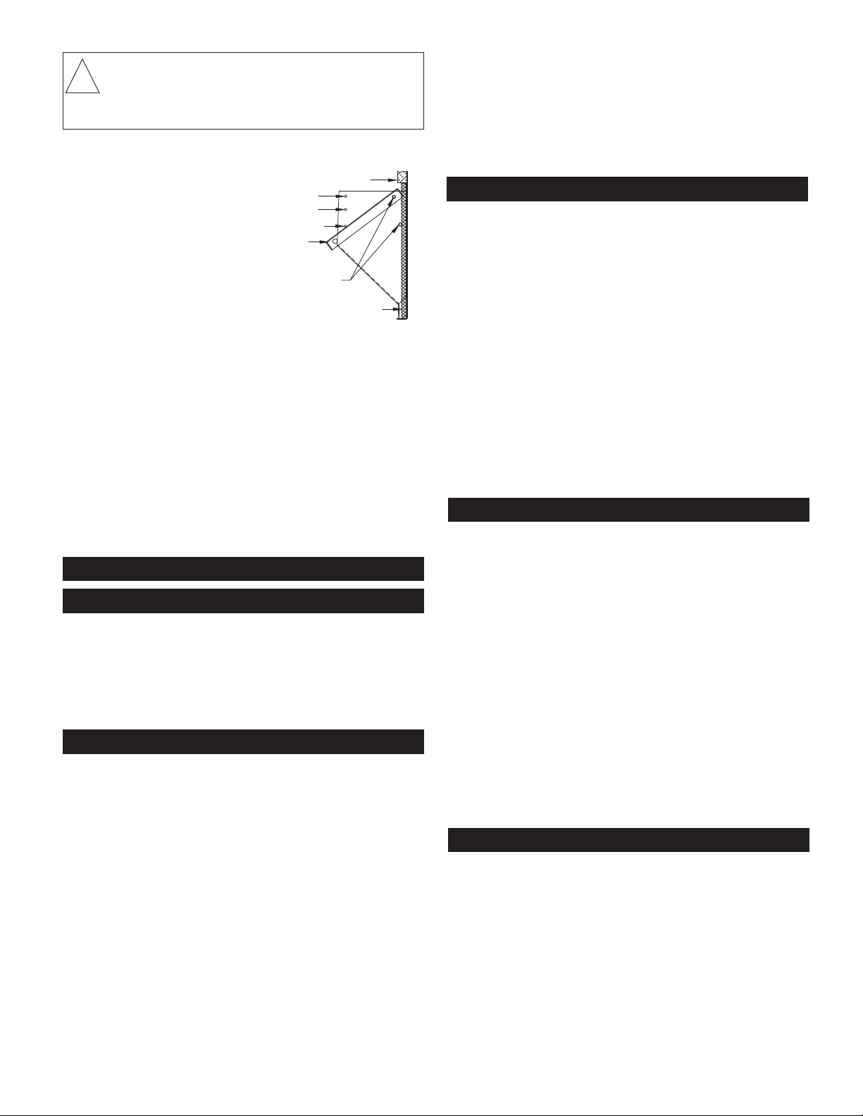
G. BREAKER/DISCONNECT ASSEMBLY
These units are standard equipped from the factory with a unit
disconnect. This is in the form of a circuit breaker (230V models) or
a disconnect (460V models). If an optional electric heat kit is to be
installed, follow the instructions included with the heater assembly.
See Figure 1 for reference.
FIGURE 1
Electrical Box
Breaker
Breaker Mount
WARNING:
!
BE IN STA LLED BY A QUALIFIED , LICENSED
ELECTRICAL EQUIPMENT SHOULD
ELECTRICIAN. IMPROPER ELECTRICAL HOOK-UP
MAY DAMAGE EQU IPM ENT, CAN CRE A TE A
HAZARD AND WILL VOID WARRANTY.
H. ELECTRICAL HOOK-UP
The line voltage electrical service can be routed through the right
side panel, the right side of the back panel, or left side panel. Each
area is supplied
1
/4"). Low voltage wiring can be routed through the right side panel.
1
with two line voltage knock-outs (
1
/2" – 3/4" and 1" –
NOTE: When routing line voltage through the return air com-
partment, conduit MUST be used (even though this is a dry area) to
comply with the NEC code. A 1
application. Refer to the ELECTRICAL DATA tables for minimum
wire size and maximum breaker size. All wire sizes listed under the
dual-feed circuit column are based on no more than thr ee (3)
conductors in the same conduit. If two circuits or more than three (3)
conductors are to be routed in the same conduit, the ampacity of the
wire size listed MUST be derated. Refer to Article 310 of the NEC
code for adjustment factors. Be sure to install a g
proper size to the unit’s equipment ground lug.
1
/4" PVC conduit is supplied for this
round wire of the
I. LOW VOLTAGE WIRING
230 volt, 1- and 3-phase units are equipped with dual-primary
voltage transformers for 208/240 volt operation. These models are
factory wired to the 240 volt tap. For 208 volt operation connect the
factory-installed black wires from the 240 volt tap to the 208 volt tap.
The acceptable voltage range of the tap is as follows.
Five ( 5) c ondu ctor thermostat wires shoul d be r u n from th e
thermostat location to the unit. Thermostat wire should be sized as
shown on the table below.
Refer to wiring diagrams for connection details.
Tap Voltage Range
240 Volt 253 - 216
208 Volt 220 - 187
Wire Gauge Maximum Length
20 45'
18 60'
16 100'
14 160'
12 250'
STAGING OF ELECTRIC HEAT
All V Series units with electric heat assemblies above 10 kW may be
wired for single- or two-stage heat. These models come factory wired
for single-stage operation. For two-stage operation, remove the
jumper bar from between the W2 and E terminal. Wire the first-stage
heat to terminal W2. Wire the second-stage heat to terminal E.
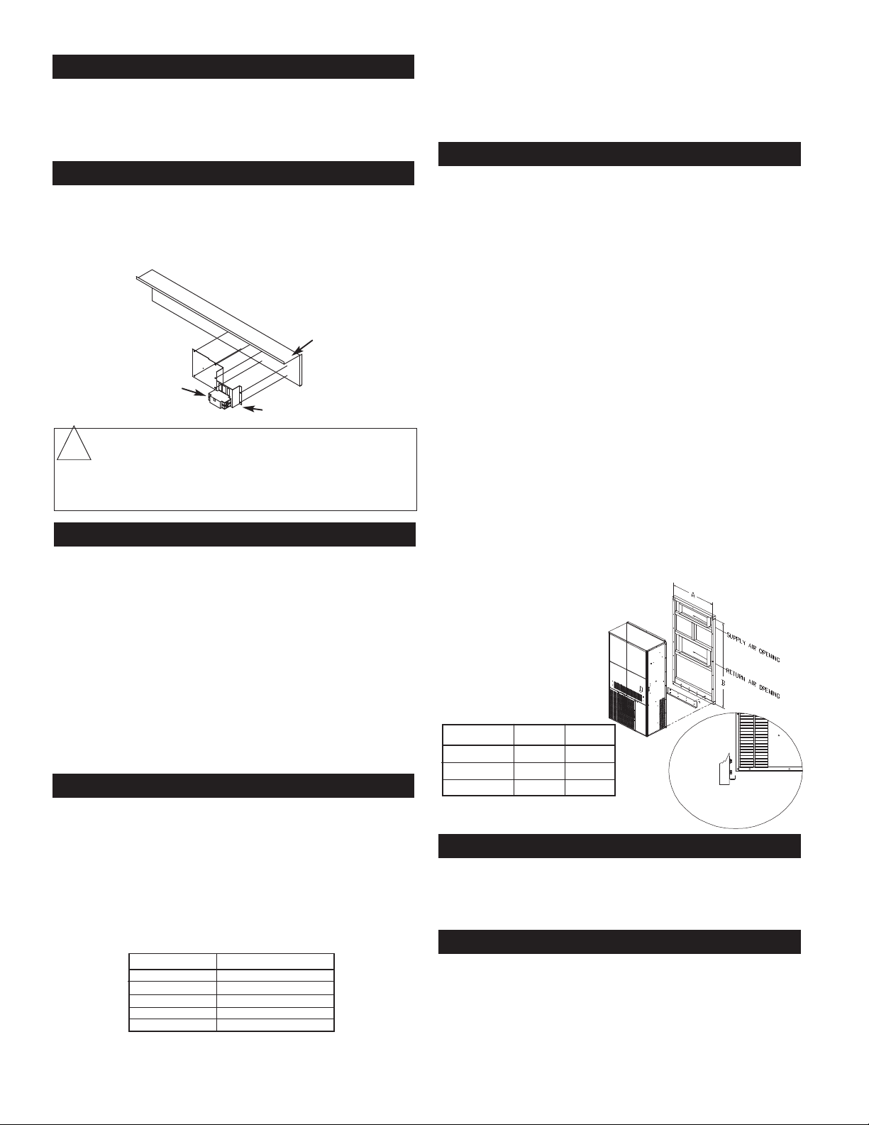
J. UNIT INSTALLATION
V SERIES UNITS ARE FOR USE IN
SINGLE-STORY BUILDINGS ONLY
1. As previously stated, the wall that the unit is to be installed
onto MUST be strong enough to support the unit under the
condition for which it will be used. For example, a unit to be
installed on a building that is intended to be transported will
req u ire m o re w a ll stre n gth than a unit installed at a
perma n ent site. Existing walls m a y n
reinforcement. NEVER RELY ON EXTERIOR SIDING OR
PLYWOOD TO SUPPOR T T HE UNIT. Fi gure 2 below
represents a typical installation of a single-story stud wall at a
permanent site. Since building materials and techniques vary
with regions and intended use, a building contractor and/or
local building code official MUST be consulted for suitable
construction methods.
2. Locate and attach the lower mounting bracket in the desired
location on the building.
3. Apply a suitable caulk across the entire length of the top rain
flashing and side mounting flanges.
4. Remove the flanges on both ends of the pallet and slide the
unit approximately 2” off the rear of pallet. Lift unit gently into
location with fork truck, taking care to align unit with lower
mounting bracket.
5. While allowing a small portion of weight on the lower bracket,
push the unit against the wall and fasten appropriately.A
drain hose is located on
may be extended for condensate removal to comply with
local codes (use fitting size or larger). Install a condensate
trap on this line.
FIGURE 2
the bottom side of the unit. The drain
eed additional
Unit Model A B
18/24 35 71
30/36 39 71
48/60 42 86
MOUNTING FLANGE BOLT
PATTERN DIMENSIONS
1
/2
K. CONDENSATE DRAIN
A3/4” drain hose is located on the bottom side of the unit. The drain
may be extended for condensate removal to comply with local
codes (use fitting size or larger). Install a condensate trap on this
line.
L. ELECTRICAL HEAT INSTALLATION
Electric heat is an option on V Series units and can be field-installed
on either single- or three-phase models.
Re fer to t he individual insta llation instructions fo r insta lling
heater kits on page 14.
4
3
/4”
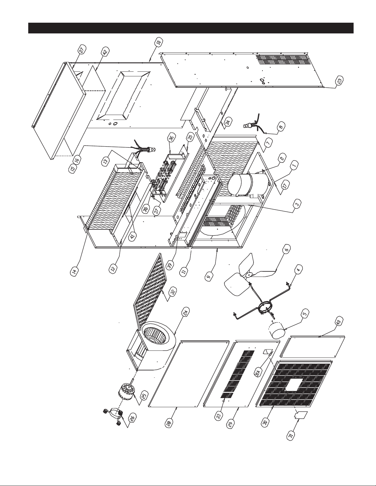
EXPLODED PARTS DRAWING — 18 / 24 / 30 / 36
5
 Loading...