

Page 1

innovative technology
ITNS-400
User Manual
Page 2

I. Unpack the ITNS-400
ITNS-400
Note
User Manual
Quick Installation Guide
This film scanner supports Windows XP, Vista/Windows7 (32/64bits) via USB 2.0
only.
We strongly suggest using a clean, dry, non-alcohol cotton swab to insert into the
film scanner slot and clean the glass surface periodically to produce a clear image.
Make sure all negative films, slide films, and cover trays are free of dust and dirt
before inserting into the ITNS-400 as this may affect the image quality when
scanning.
When cleaning films, please use a professionally recommended purger from a
photo store to avoid damaging old or precious films.
-1-
Page 3

II. Driver Installation
To use the ITNS-400, please complete the following installation in advance.
1. Turn on the computer
2. Insert the installation CD into the CD-ROM drive and the installation CD
menu will appear.
3. Choose Installation.
-2-
Page 4

4. Follow the on-screen instructions. (Windows XP, Vista/Windows7)
-3-
Page 5

-4-
Page 6

-5-
Page 7

-6-
Page 8

5. After completing software installation, please connect ITNS-400 to PC. The
New Hardware Wizard will detect a new device.
-7-
Page 9

6. Select “Yes” in XP or “Locate and install driver software (recommended)” in
Vista/Windows7 OS.
-8-
Page 10

7. After completing the installation, the filmscanner is ready to start with
“35mm FilmScanner” Image Scan Tool under program files. (Windows XP,
Vista/Windows7 Restart is not required, but it is recommended to restart
)
your PC after installation/un-installation.
III. Using the ITNS-400
Power status LED
Copy button
USB Cable
Film Slot
-9-
Page 11

Installing film into the film holder
Install slide Film into the holder entitled “Slides Only”
1. Open the slide holder as illustrated
2. Place slide in recessed slot in holder 3. Close the film holder
Install Negative Film into the holder entitled “Negative Film Only”:
1. Open the film holder as illustrated
2. Install film into negative film slot
3. Close the film holder
-10-
Page 12
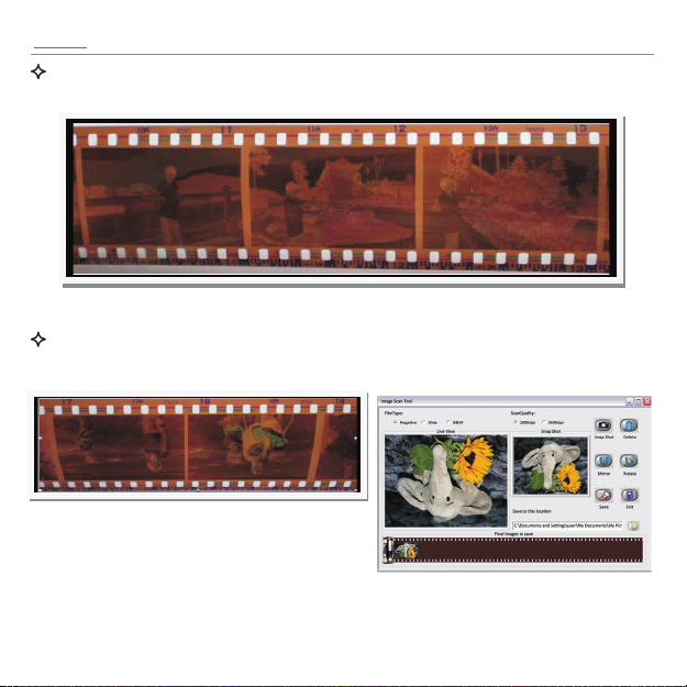
Note
To avoid a mirror image, follow the serial numbers (from left to right) on
top of film when installing negative film into holder.
Figure 1
If the image is upside down [see fig.2], the image can be corrected by
“Rotate” function in Image Scan Tool after capture [see fig.3].
Figure 2
Figure 3
-11-
Page 13
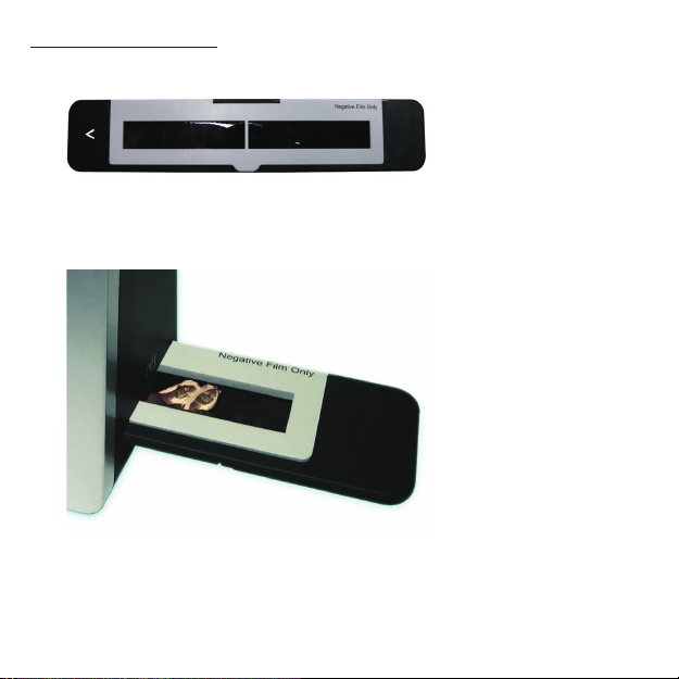
How to use ITNS-400
1. Put Film into film holder
2. Insert the film holder into the right side of the ITNS-400 unit
-12-
Page 14
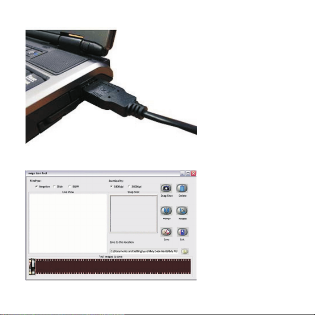
3. Connect ITNS-400 to PC
4. Click “Image Scan Tool” to enter operation interface as below
-13-
Page 15
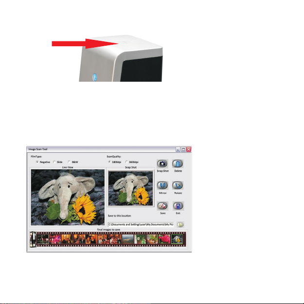
5. Press “Copy” button to capture the image
6. Process necessary modification by function buttons in right hand side
-14-
Page 16
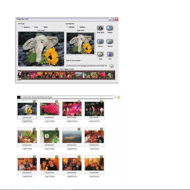
7. Save captured images to PC
8. Get fimal images from PC for further review and edit
-15-
Page 17
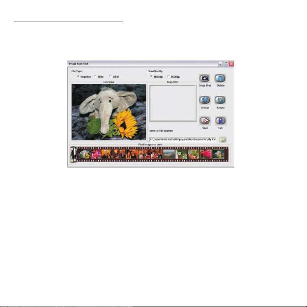
User interface introduction
When user selects a “Negative” source, the image in “Live View” window will
be exactly like the processed result.
-16-
Page 18
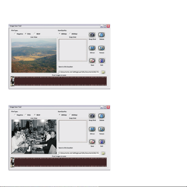
If device processes a slide, the “Live View” will show a color image and the
FilmType will remain the same.
This is the live view under black and white negative option.
-17-
Page 19
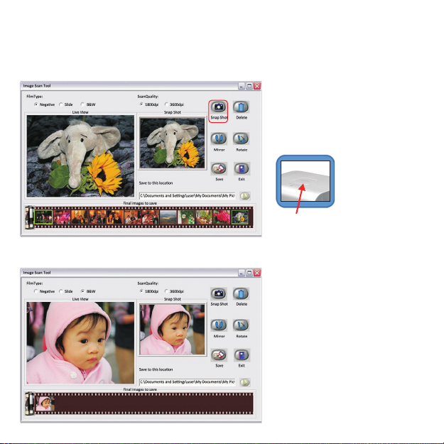
User can convert images from traditional film to digital either by “Snap Shot”
button in Image Scan Tool or the button on top of filmscanner. Then, the
capture result will appear in the “Snap Shot” and “Final images to save”
window.
Touch button
All of the effects in Image Scan Tool will be ready for instant preview in “Snap
Shot” and “Final images to save” window.
-18-
Page 20
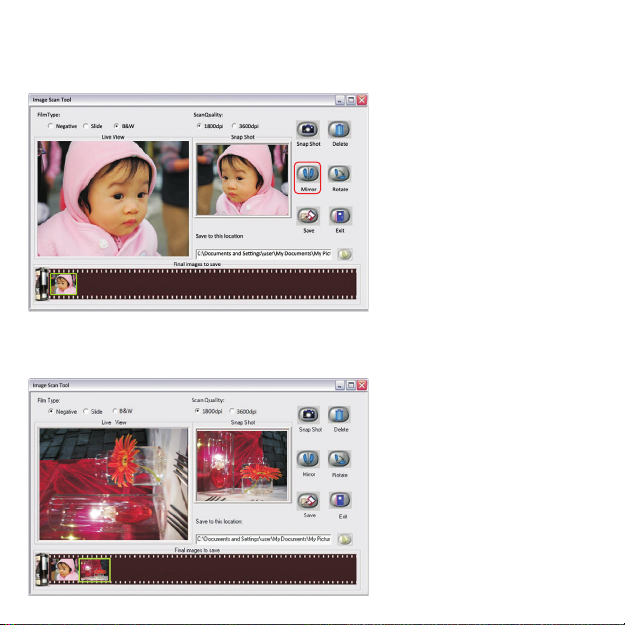
Apply the Mirror function by pressing the “Mirror” icon, that will flip the
image and be shown in the “Snap Shot” window as well as the “Final images
to Save”.
Or apply the Rotate function by pressing “Rotate” button, the image will be
rotated 90 degrees each time. Images can be continuously rotated a full 360
degrees or until desired.
-19-
Page 21
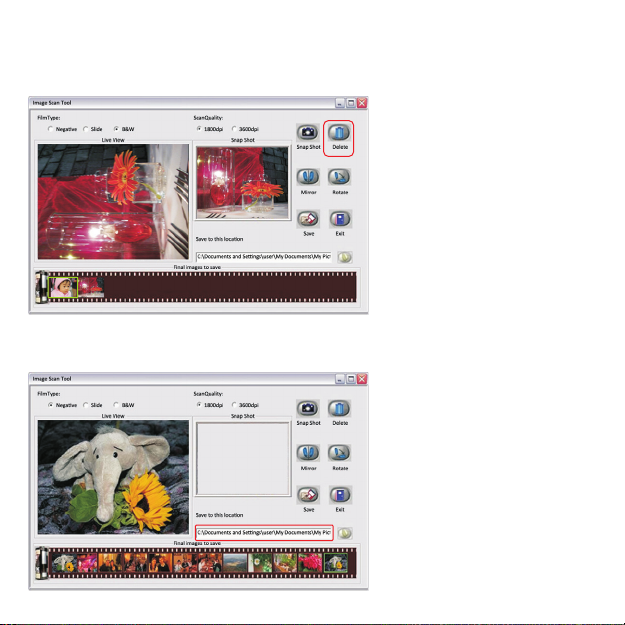
If the user wishes to delete a specific image from the capture pool, simply
click the image under “Final image to save” again, then the selected image
can be deleted by applying the “Delete” button.
After modification, user can save images to the default location at
“C:\Documents and Settings\Users\My Documents\My Pictures”.
-20-
Page 22
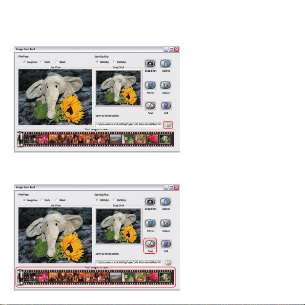
Or define preferable location for saving captures images by pressing the
directory button. Another window will pop out for user to select required
location.
Once press “Save” key, all of captures images will be saved into defined
location. The “final image” saving window shall be empty after press the
“Save” button.
-21-
Page 23
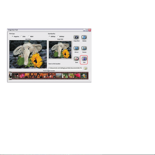
When the capture is complete, the user can press “Exit” button to quit this
Image Scan Tool, Then, review captured images or process more fancy
modification with bundle software for PC.
-22-
Page 24

IV. Specification
Image Sensor: 5 mega CMOS sensor
Lens: F no.=2.0, 4 Glass elements,
Focus Range:
Exposure Control:
Color Balance
Scan Quality
Data Conversion
Scan Method
Light Source
Interface:
Power:
Dimensions
Weight
Operating Systems
Fixed focus
Automatic
Automatic
1,800 dpi /3600 dpi (SW interpolation)
10 bits per color channel
Single pass
Back light (3 white LEDs)
USB 2.0
USB port
W100.6 x L90.5 x H150.3mm
0.39kg
Windows XP/Vista/Windows 7
-23-
Page 25

V. Cleaning the ITNS-400
Please remove the film holder from device when you notice any dust in the
live view window.
Then you can use the cleaning brush to wipe away dust.
Note
We strongly suggest using a clean, dry, non-alcohol cotton swab to clean
the glass surface periodically to produce a clear image during operation.
-24-
Page 26
ITNS-400 Trouble shooting
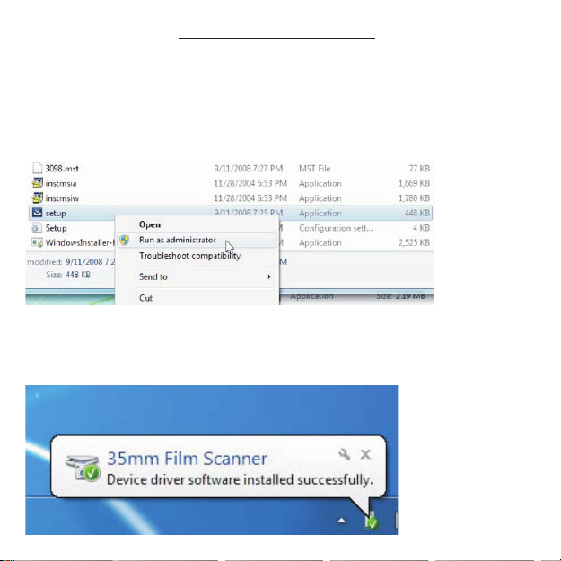
Question 1. How to install ITNS‐400 driver?
Solution:
01 Put FilmScan Driver CD ROM into your CD player
02 Open the X CD ROM Driver folder
03 Click mouse right buttonon setup exe and click “Run as administrator”
to install driver
04 The InstallShield Wizard will show the message of “InstallShield Wizard
Completed once the driver installed ready..
05 Connect ITNS-400 to your PC the PC will complete the device driver
installation and confirm driver installed successfully
:
.‐ .
. ( ‐ ):\ \ .
..,
.
.,
.
-25-
Page 27
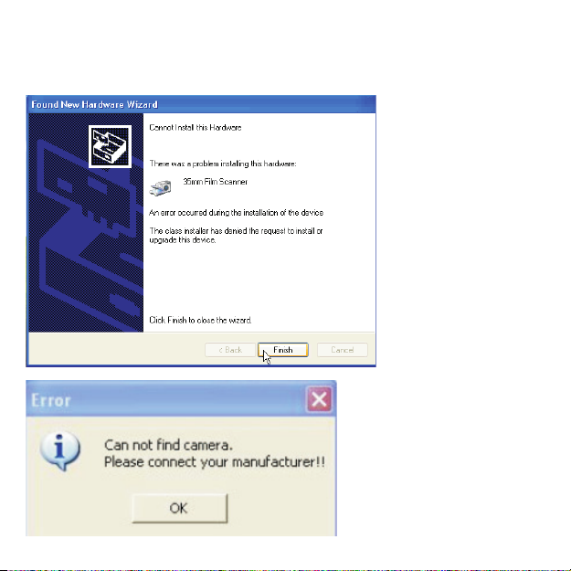
Question 2. Came up the error message “Cannot Install This Hardware” or
Can not find camera. Please connect your manufacturer” or “Acquire
“
Source Failed…Restart DSM”
-26-
Page 28
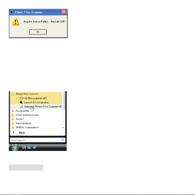
Solution:
01.Check your USB cable to make sure it is well connected to your PC and
your device.
02.Check your PC to verify the driver is installed properly.
03. Uninstall the existing driver from your system.
a. Using the uninstall program of ITNS‐400 application
Run start All programs (Vista/Win7) or Program files (XP) 35mm film
scanner 35mm film scanner Uninstall 35mm Film Scanner
→→
→→
b. or Using the tool in device manager
(1) Open Device Manager.
Windows XP
Open Start Setting Control Panel System Hardware Device
→→ →→ →
Manager
-27-
Page 29
Windows Vista
Open Start Control Panel System Device Manager
→→→
Wondows 7
Open Start Control Panel System and Security System Device
→→ →→
Manager
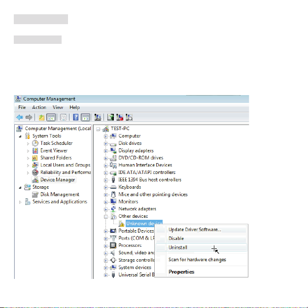
(2) Click the right button of mouse from “Unknown device” and uninstall the
driver.
04. Re‐install proper driver version again.
-28-
Page 30
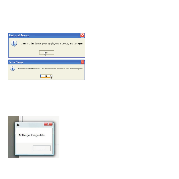
Question 3 If you can t uninstall the driver or came up the error
message Can’t find the device you may plug‐in the device and try
.
’
“,
again.” or “Failed to uninstall the device. The device may be required to
boot up the computer.”
Solution
Please refer to Question 2 solution and reboot your computer, if it still
can’t work please contact us through e-mail
:
,
support ithomeproducts com@ .
Question 4 Run the ITNS‐400 application and come up the error
message Fail to get image data
.
“”
OK
Solution
Close the application then re‐start the ITNS‐400 application again:.
-29-
Page 31
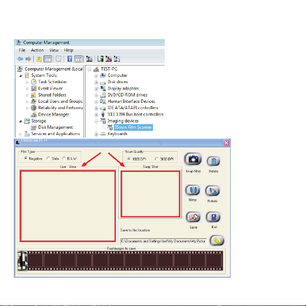
Question 5 You can t see the pre‐view image from ITNS‐400 application
when you have re‐installed driver and device status is completed
.’
.
Reason: Devices confliction. (Such as USB cameras or devices.)
-30-
Page 32
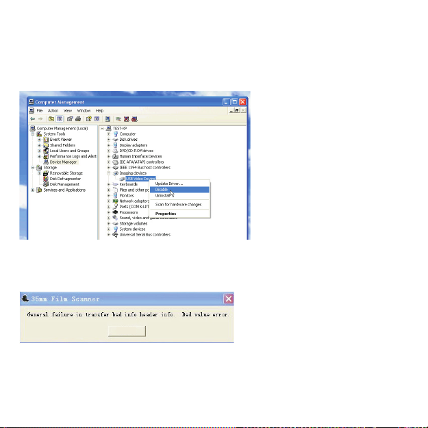
Solution:
01. Disable the other imaging devices by using bundled program in standard
package first or disable it by the option under Imaging device when press
right button of mouse.
02. Re‐start ITNS‐400 application again.
Question 6. Come up the error message “General failure in transfer bad info
header info. Bad value error”.
OK
Reason: Plug device into USB1.1 port.
Solution:
ITNS‐400 only supports USB 2.0. Please verify if your PC is compatible with
USB2.0.
-31-
Page 33
01 Open Device Manager.
Windows XP
Open Start Setting Control Panel System Hardware Device Manager
→→ →→ →
Windows Vista
Open Start Control Panel System Device Manager
→→→
Windows 7
Open Start Control Panel System and Security System Device Manager
→→ →→
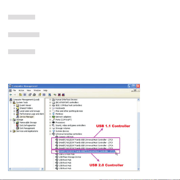
02 Your computer must with a USB 2.0 Controller in Universal Serial Bus
controllers. The figure below shows the difference between USB1.1 and 2.0.
There must be a “USB2” for USB 2.0 controller.
-32-
Page 34

InnovativeTechnologyElectronicsCorp
LimitedWarranty
90Days Labor One Year Parts
Innovative Technology Electronics Corp IT warrants the product to be free from Defects in
materials under normal use for a period of One Year fom the date of the orginal purchase The
Warrantyis Not transferable ITagrees within theinitial 90 Day period to repairtheproductif
itis determinedtobedefective at NoCharge It isfurtheragreedthatIT willcover thecost to repairor
replacedamaged Parts onlyfora totalperiodof One Year fromthe dateoftheoriginal purchase
The warrantydoes notcovercosmetic damage antennas AC cords cabinets headbands ear-pads
or damage due to line power surges connection to improper voltage supply or settings misuse
mishandling accident acts ofGodor attempted repair byanunauthorized serviceagent
Toabtain service the originalpurchaser MUSTpresent asalesreceipt/proof ofpurchaseindicating date
of purchase amount paid and place of purchase Send the unit prepaid tothe address below in the
original packaging orreasonablesubstitute toprevent damage You MUST include yourfull name
shippingaddressandtelephone number No return willbe shippedbackto aPOBox Pleaseinclude your
check ormoney orderin the amountof $12 00 payable toInnovative Technology ElectronicsCorp to
coverhandling andreturnshippingcharges IT will notberesponsible for delays orunprocessedclaims
resultingfroma purchaser s failure to provide anyorall ofthe necessaryinformation
,
“” . , “ ” ,
“” “ ” .
,, .
,
,, .
’.
Sendall inquiresorreturns to
CustomerService Dept
InnovativeTechnologyElectronicsCorp
4Anchor way PortWashington NY 11050
:-- -(--- )
Tel 1 877 ITECH 97 1 877 483 2497
:. .
Website www ithomeproducts com
:@ .
EMAIL support ithomeproducts com
.
,,
.
.( ) “ ”
“” .
“”.
,,,, ,,
,,,
..
., .
.( )
.“ ” ,
:
.
There are no express warranties except as listed above
REPAIR OR REPLACEMENT AS PROVIDED UNDER THIS WARRANTY IS THE EXCLUSIVE REMEDY OF THE
CUSTOMER IT SHALL NOT BE LIABLE FOR ANY INCIDENTAL OR CONSEQUENTIAL DAMAGES FOR
BREACH OF ANY EXPRESS OR IMPLIED WARRANTY ON THIS PRODUCT EXCEPT TO THE EXTENT
PROHIBITED BYAPPLICABLE LAW ANY IMPLIEDWARRANTY OF MERCHANTABILITY OR FITNESS FORA
PARTICULAR PURPOSE ON THIS PRODUCT IS LIMITED IN DURATION TO THE DURATION OF THIS
WARRANTY
Some states do not allow the exclusion or limitation of incidental or consequential damages or
limitationson howlonganimplied warranty lasts so theaboveexclusionsorlimitationsmay notapplyto
you This warranty gives you specific legalrights and you mayalso have other rights which vary from
stateto state
,( )
.
.
.,
.
,
,
Page 35

Instructions shall caution users that modifications not approved by the party responsible
for compliance couldvoid user's authorityto operate the equipment.
The following or equivalent as appropriate:
“NOTE: This equipment has been tested and found tocomply with the limits for a Class B
digital device, pursuant to Part 15 of the FCC Rules. These limits are designed to provide
reasonable protection against harmful interference in a residential installation. This
equipment generates, uses and can radiate radio frequency energy and, if not installed
and used in accordance with the instructions, may cause harmful interference to radio
communications. However, there is no guarantee that interference will not occur in a
particular installation.
If this equipment does cause harmful interference to radio or television reception, which
can be determinedby turning the equipment off and on, the user is encouraged to try to
correct the interference by one or more ofthe following measures:
Reorient or relocate the receiving antenna.
●
Increase theseparation between the equipmentand receiver.
●
●
Connect the equipment into an outlet on a circuit different from that to which the
receiver is connected.
●
Consult thedealer or anexperienced radio/TV technicianforhelp.”
Statement that the productcomplies with Part 15 (i.e. “This device complieswith Part15
of theFCC Rules.Operation is subject to the following twoconditions: (1) This device may
not cause harmful interference, and (2) this device must accept any interference
received, including interference that may causeundesired operation.”)
CALIFORNIA PROP 65 WARNING
WARNING : This product contains chemicals known to the State of California to cause
birth defectsor other reproductive harm.For moreinformation on these regulations and
a list of chemicals, log on the following website address:
http://www.oehha.ca.gov/prop65.html
Page 36

Driver Revision: 1.0_1
 Loading...