


End User Instructions
Wingo 3524 HS
Swing Gate Oper
ato
r

Ver: 2015.001
2
Introduction.
Page 3
Be Safe! Instructions, warnings and obligations.
Page 5
How to use the manual override.
Operating mode definitions and examples
Page 6
Ends of travel referencing.
Page 7
How the collision sensing will respond to a physical overload.
Page 8
How the safety infra-red beams function.
Page 9
Example of button triggers: Standard mode.
Page 10
Example of button triggers: Simple auto-close mode.
Page 11
Example of button triggers: Condominium mode.
Page 12
How the pedestrian trigger functions.
Page 13
How the loop detector trigger functions.
Page 14
How the overlapping gates delay mode functions.
Page 15
How the auxiliary relay responds in: Strike lock mode.
Page 16
How the auxiliary relay responds in: Magnetic lock mode.
Page 17
How the auxiliary relay responds in: Courtesy light mode.
Page 18
How the auxiliary relay responds in: Receiver relay mode.
Page 19
How positive close mode functions.
Page 20
Using the holiday lock-out mode.
Page 21 Using the auto-close override/party mode.
Troubleshooting.
Page 22
Status LED, buzzer and display indications.
Useful information.
Page 23
Receiver user address log.
Page 24
Warranty.
For any assistance with this product, which is not covered in this manual, please contact your service
provider/installer.
Contact details of service provider/installer.
Company name:
Technician:
Contact number:
Email address:
Date of installation:

Ver: 2015.001
3
Be Safe!
WARNING!! These are the general safety obligations for the installers and users of ET Systems (Pty) Ltd
automation equipment.
1. Only suitably qualified persons, may install, repair or service the product. Unless expressly indicated in the user
instructions, no user serviceable components can be found inside any ET Systems (Pty) Ltd automation product.
2. It is important for personal safety to study and follow all the instructions carefully. Incorrect installation or misuse may
cause serious personal harm.
3. Keep the instructions in a safe place for future reference.
4. This product was designed and manufactured, strictly for the use indicated in the accompanying documentation. Any
other use not expressly indicated in the documentation, may damage the product and/or be a source of danger. ET
Systems (Pty) Ltd cannot accept responsibility for improper use or incorrect installation of this product.
5. ET Systems (Pty) Ltd cannot accept responsibility if the principles of good workmanship are disregarded by the installer.
6. ET Systems (Pty) Ltd cannot accept responsibility regarding safety and correct operation of the automation, if other
manufacturers’ equipment is added to this product.
7. Do not make any modifications or alterations to this product. Do not substitute any component of this product with
any other component not expressly designed into this product.
8. Anything other than expressly provided for in the accompanying instructions is not permitted.
Prior to installation:
1. All unnecessary ropes, chains and fasteners must be removed and all unnecessary latches or locks must be disabled from
locking.
2. The gate or door must be balanced correctly where it, neither opens nor closes from any position under its own load.
When operated by hand the gate or door should be free of hindrance and easily moved (In the case of a garage door if the
balancing springs need to be adjusted the adjustment should only be carried out by a qualified and experienced person).
3. The construction of the gate or door must be sound and automatable. It is the responsibility of the installer to
ensure that the mechanical components of the gate or door system are sufficient to withstand the necessary forces in
cases of overload.
4. It is the responsibility of the installer to ensure the gate or door is sufficiently trapped within its range of travel by means of
mechanical ends of travel stoppers.
5. Ensure all fixed mounting points, like the wall above the door in a garage door system or the posts in a swing gate
system, are sound and strong enough to allow proper fixing of the operator.
6. It is the responsibility of the installer to ensure the installed position selected for this product, falls within the
limitations of the products ingress protection rating.
7. Ensure the area of installation is not subject to explosive hazards. There should be no volatile gasses or fumes as these
can present a serious safety hazard.
8. All ET Systems (Pty) Ltd garage door operators are supplied with a sealed 15A safety plug on lead for use in an
electrical code of practice approved plug point. Do not extend, modify or replace the plug lead unless duly qualified as
an electrician. Before installing the unit, ensure the mains supply is switched off.
9. ET Systems (Pty) Ltd gate operators are supplied with a terminal connection for the electrical supply beneath the screwed
down cover of the operator. In the case of a model requiring 220Vac supply at the operator, an all pole negatively biased
switch, with a contact opening of greater than 3mm must be installed within 1,5m of the operator. This switch must be
clear of all workings of the system and must be in a position secure from public access. This switch and its connections
must be inspected and pass
ed by a certified electrician prior to using it.
10. It is the responsibility of the installer to ascertain that the designated persons (including children) intended to use the
system, do not suffer reduced physical sensory or mental capabilities, or lack of experience and knowledge, unless they
have been given supervision or instruction concerning the use of the system by a person responsible for their safety.
11. The drive may not be installed on a door incorporating a wicket door, unless the drive is disabled by the release of the
wicket door. (Wicket door :- A pedestrian door within the main gate or door)
Installation:
1. Ensure the working area is clear of obstructions and obstacles.
2. Install the safety warning sticker within clear view of where the gate or door will be operated from. Typically this would
be adjacent to any fixed trigger switches or on the gate or door itself.

Ver: 2015.001
3. The emergency manual release must be installed where it is no higher than 1.8m from the floor level. This would apply
to the cord in a garage installation or the lockable lever in a gate installation.
4. Any additional fixed door control switches such as wall consoles or keypads, if installed, must be at a height of at least
1,5m, within clear sight of the gate or door and away from any moving components of the system.
5. It is highly recommended that a set of safety infra-red beams be used in conjunction with this product. The safety
beams must be installed in such a way that the product is prevented from running when anything is in the path of the door
or gate.
6. Over and above the recommendation to use safety infra-red beams with this product it is mandatory to install and use a
safety beam set when using the automatic closing feature. It is recommended that a warning light be fitted to any
automation system.
7. The gate or door warning labels must be installed in a prominent place and/or adjacent to any fixed controls that
trigger the system. These must be in clear line of sight of the gate or door opening.
8. The emergency manual release instruction label must be installed on or adjacent to the emergency manual release
mechanism.
After Installation: It is the responsibility of the installer to ensure the user:
1. Is proficient in the use of the manual emergency release mechanism.
2. Is issued with the documentation accompanying this product.
3. Understands that the gate or door may not be operated out of clear sight.
4. Ensures that children are kept clear of the gate or door area at all times, and that children do not play with the remote
transmitters or any fixed trigger switches linked to the system.
5. Is instructed not to attempt to repair or adjust the automation system and to be aware of the danger of continuing
to use the automation system in an unsafe condition before a service provider attends to it.
6. Is proficient in testing the unit’s safety obstruction sensing system.
7. Is aware of what to check for with regards to wear and tear that may need to be attended to from time to time by the
service provider.
8. Is aware that a fatigued battery may not be disposed of in the general refuse and must be handed in at a battery
merchant for safe disposal. Before removing the battery from the system the household mains must be disconnected. In
the case of the motor unit being removed and scrapped, the battery must be removed first.

Ver: 2015.001
5
How To Use The Manual Override.
To manoeuvre the gates manually by hand, you need to disengage the gearboxes by completing the following steps.
Putting the motors into manual override.
Slide the lock cover open.
Insert key and turn to unlock.
Lift the manual override lever.
You are now able to manouvre the gates to any position by hand.
Engaging the motors after manual override.
Lower the manual override lever
back down.
Using the key lock the lever in place.
Cover the lock again by sliding the
lock cover over it.
You are now able to use the gate automation again.

Ver: 2015.001
6
Basic operating features.
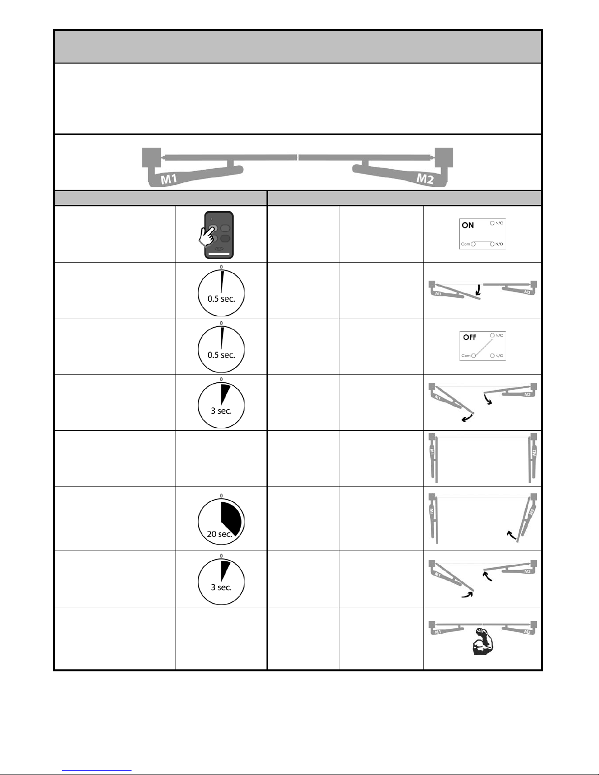
Manual override and end of travel referencing.
The ends of travel are consistently being monitored by the gate control software.
Whenever the gates are placed in manual override (Gates fre
e to be manoeuvred by hand) the chances of engaging them again in the
exact same position is nearly impossible. For this reason the software will automatically go into an end of travel referencing operation.
NB! A momentary trigger on the BT, PED or BM inputs will pause the referencing routine. A repeat BT or PED trigger will allow it to
resume.
Action
Response
Engage the motors
again after moving the
gates.
No gate movement.
No Buzzer
tones.
Momentary BT trigger.
Gates begin closing if the last
operation before moving them
was an opening operation. If the
gates were closing before the
manual manoeuvre, then they
will begin opening.
No buzzer
tones.
Gates run up hard onto
the end stops as they
are out of reference
with the last position
memorized by the
control card.
Control card begins running the
standard safety overload routine
for that direction.
Buzzer beeps
confirmation of
which gate,
overloaded.
See trouble
shooting guide.
As soon as the first gate
passes the point at
which it was re-engaged
the control card will
know it is out of
reference to the gate
positions.
Buzzer begins beeping
intermittently and display shows
rEF.
Gate 1 continues to open slowly
searching for the open stopper.
ref
Gate 1 reaches the
open stopper and
surges up.
Buzzer continues beeping and
display continues showing rEF.
Gate 2 begins opening slowly.
ref
Gate 2 reaches the
open stopper and
surges up.
Buzzer continues beeping and
display continues showing rEF.
Referencing pauses with both
gates in the open position. The
system now waits for an
instruction to continue.
ref
Momentary BT or PED
trigger.
Buzzer continues beeping and
display continues showing rEF.
Gate 2 begins closing
ref
Gate 2 reaches closed
position.
Buzzer continues beeping and
display continues showing rEF.
Gate 1 begins closing
ref
Both gates reach the
closed position.
Buzzer silences and display
reverts to ready.
rdy
The system is now ready for normal use.

Ver: 2015.001
7
Basic operating features.
Collision sensing and safety overload routines.
In the case of one of the gates
colliding with an obstruction such as a person passing through the entrance way, the collision sensing
will automatically detect the collision and the system will run a safety overload routine.
Safety overloads routine while gates are opening.
Action Response
Gates busy running open
Gate collides with
pedestrian for
example.
Both gates stop running
Buzzer beeps.
x1 = Gate 1
collided
x2 = Gate 2
collided
The gate that was
obstructed backs away
momentarily from the
collision point and stops.
No buzzer tones.
Both gates remain stopped
and the system waits for
next trigger to close.
No buzzer tones.
Safety overloads routine while gates are closing.
Action Response
Gates busy running closed
Gate collides with
pedestrian for
example.
Gates stop closing and begin
opening immediately.
Buzzer beeps.
x1 = Gate 1
collided
x2 = Gate 2
collided
Both gates stop in the full
open position and wait for
next trigger to close.
No buzzer tone.

Ver: 2015.001
8
Basic operating features.
Safety infra-red beams function.
If the safety beam input has been switched on, the control card will constantly monitor to ensure a set of safety beams is installed.
NB! If the BT input mode has been set to either simple auto-close or condominium mode, the safety beam input is forced on.
If the BT input has been set to standard mode and either the loop detector or pedestrian input is activated, the safety beam input is
forced on for that transaction only.
Below is an example of how the gates will behave whenever the safety beam input is activated.
Gates in the closed position
Action Response
Momentary BT trigger.
Gates begin
opening.
No buzzer tones.
Safety beam input
triggered.
Gates
continue
opening.
No buzzer tones.
At full open position. Gates stop. No buzzer tones.
Momentary BT trigger.
Gates begin
closing.
No buzzer tones.
Safety beam input
triggered.
Gates stop
closing and
begin
opening
immediately.
No buzzer tones.
At full open position.
Safety beam input still
triggered.
Gates stop. No buzzer tones.
Momentary BT trigger.
Safety beam input still
triggered.
Gates remain
open.
No buzzer tones.
Momentary BT trigger.
Safety beam input no
longer triggered.
Gates begin
closing.
No buzzer tones.
At full closed position. Gates stop. No buzzer tones.

Ver: 2015.001
9
Basic operations.
“BT” Button triggers.
Standard mode.
The BT functions are the primary full gate opening functions for motor vehicle access.
There are two ways of activating the “BT” functions on this control card. Either via the hardwired BT input or the BT receiver channel.
In Standard mode the gates respond to each BT trigger.
In Standard mode you have access to the following advanced features: - Holiday lock-out and Party mode.
Gates in the closed position
Action Response
Momentary BT trigger.
Gates begin
opening.
No buzzer tones.
At full open position. Gates stop. No buzzer tones.
Momentary BT trigger.
Gates begin
closing.
No buzzer tones.
Momentary BT trigger.
Gates stop
closing and begin
opening
immediately.
No buzzer tones.
Momentary BT trigger.
Gates stop. No buzzer tones.
Momentary BT trigger.
Gates begin
closing.
No buzzer tones.
At full closed position. Gates stop. No buzzer tones.

Ver: 2015.001
10
Basic operations.
“BT” Button triggers.
Simple auto-close mode.
The BT functions are the primary full gate opening functions for motor vehicle access.
There are two ways of activating the “BT” functions on this control card. Either via the hardwired BT input or the BT receiver channel.
Simple auto-
close mode functions exactly the same as standard mode except that the gates will close automatically after the
programmed BT auto-close timer has timed out.
In Simple auto-close mode you have access to the following advanced features: - Holiday lock-out and Party mode.
NB! For any auto-close feature to work, a pair of safety infra-red beams must be installed and functioning correctly. If no safety
infra-red beams are installed then the gates will open but not close again.
Gates in the closed position
Action Response
Momentary BT trigger.
Gates begin
opening.
No buzzer tones.
At full open position. Gates stop. No buzzer tones.
Momentary BT trigger or auto-
close timer times out.
Gates begin
closing.
No buzzer tones.
Momentary BT trigger.
Gates stop
closing and begin
opening
immediately.
No buzzer tones.
Momentary BT trigger.
Gates stop. No buzzer tones.
Momentary BT trigger or auto-
close timer times out.
Gates begin
closing.
No buzzer tones.
At full closed position. Gates stop. No buzzer tones.

Ver: 2015.001
11
Basic operations.
“BT” Button triggers.
Condominium auto-close mode.
The BT functions are the primary full gate opening functions for motor vehicle access.
There are two ways of activating the “BT” functions on this control card. Either via the hardwired BT input or the BT receiver channel.
In Condominium auto-close mode, all BT triggers are treated as open, keep opening, keep open or re-open triggers. The gates will only
close once the BT auto-close timer has timed out.
In Condominium auto-close mode the following advanced features are not available: - Holiday lock-out and Party mode.
NB! For any auto-close feature to work, a pair of safety infra-red beams must be installed and functioning correctly. If no safety
infra-red beams are installed then the gates will open but not close again.
Gates in the closed position
Action Response
Momentary BT trigger.
Gates begin
opening.
No buzzer tones.
Momentary BT trigger.
Gates continue
opening.
No buzzer tones.
At full open position. Gates stop. No buzzer tones.
BT auto-close timer times out.
(Any BT trigger or safety beam
trigger while the timer is
counting down, resets the
timer)
Gates begin
closing.
No buzzer tones.
Momentary BT trigger.
Gates stop
closing and begin
opening
immediately.
No buzzer tones.
At full open position. Gates stop. No buzzer tones.
BT auto-close timer times out.
(Any BT trigger or safety beam
trigger while the timer is
counting down, resets the
timer)
Gates begin
closing.
No buzzer tones.
At full closed position. Gates stop. No buzzer tones.

Ver: 2015.001
12
Basic operations.
“PED” Pedestrian trigger.
The PED trigger is a higher security option and is used when access to or from the property is limited to exclude motor vehicles.
Pedestrian mode makes use of a mandatory auto-close timer that prevents the gate from being left open after each transaction.
There are two ways of
activating the “PED” functions on this control card. Either via the hardwired PED input or the PED receiver
channel.
NB! For any auto-close feature to work, a pair of safety infra-red beams must be installed and functioning correctly. If no safety
infra-red beams are installed then the gate will open but not close again.
Gates in the closed position
Action Response
Momentary PED trigger.
Gates remain closed.
Wait for warning tones to
finish.
Gate 1 begins opening.
No buzzer
tones.
At preprogramed
pedestrian open position.
Gate stops.
No buzzer
tones.
Pedestrian auto-close
timer times out.
Gate remains at
pedestrian opening.
Wait for warning tones to
finish.
Gate begins closing.
No buzzer
tones.
Momentary PED trigger.
Gate stops and
immediately begins
opening.
No buzzer
tones.
At full open position. Gates stop.
No buzzer
tones.
Auto-close timer times
out.
Gate remains at
pedestrian opening.
Wait for warning tones to
finish.
Gate begins closing.
No buzzer
tones.
At full closed position. Gate stops.
No buzzer
tones.

Ver: 2015.001
13
Basic operations.
“LPT” Loop detector trigger input.
The Loop trigger mode is exactly the same as Condominium auto-close mode.
The only way to trigger loop detector mode is via the hardwired LPT input.
In Loop detector mode, a LPT trigger is treated as open, and any BT or LPT trigger is treated as a keep opening, keep open triggers or
re-open trigger while the gates are running. The gates will only close once the LPT auto-close timer has timed out.
NB! For any auto-close feature to work, a pair of safety infra-red beams must be installed and functioning correctly. If no safety
infra-red beams are installed then the gates will open but not close again.
Gates in the closed position
Action Response
Any LPT trigger.
Gates begin
opening.
No buzzer tones.
Any LPT trigger.
Gates continue
opening.
No buzzer tones.
At full open position. Gates stop. No buzzer tones.
LPT auto-close timer times out.
(Any BT, LPT or safety beam
trigger while the timer is
counting down, resets the
timer)
Gates begin
closing.
No buzzer tones.
Any LPT trigger.
Gates stop
closing and begin
opening
immediately.
No buzzer tones.
At full open position. Gates stop. No buzzer tones.
LPT auto-close timer times out.
(Any BT, LPT or safety beam
trigger while the timer is
counting down, resets the
timer)
Gates begin
closing.
No buzzer tones.
At full closed position. Gates stop. No buzzer tones.

Ver: 2015.001
14
Basic operations.
“DLY” overlapping gates, delay mode.
Overlapping gates, delay mode can be set to work with any other mode of operation.
When activated gate 1 will always open first and then gate 2 will follow. Gate 2 will always close first and gate 1 will follow.
Below is an example of delay mode working when Condominium mode is active.
Gates in the closed position
Action Response
Momentary BT trigger.
Gate 1 begins
opening.
No buzzer tones.
After preprogramed
overlapping gate delay time.
Gate 2 begins
opening.
No buzzer tones.
At full open position. Gates stop. No buzzer tones.
BT auto-close timer times out.
(Any BT trigger or safety beam
trigger while the timer is
counting down, resets the
timer)
Gate 2 begins
closing.
No buzzer tones.
After preprogramed
overlapping gate delay time.
Gate 1 begins
closing.
No buzzer tones.
At full closed position. Gates stop. No buzzer tones.

Ver: 2015.001
15
Advanced features.
Auxiliary relay modes.
“Lc1” Strike lock mode.
With “Lc1” Strike lock mode selected, the auxiliary relay will pulse for 1 second, half a second before the gates open from any position.
Whenever a lock is installed with the system a separate battery backed up power supply, matching the lock load, must be installed.
Failure to do this can damage the charger and battery of the control unit.
Below is an example of “Lc1” Strike lock mode working when Condominium mode and delay mode is active.
Gates in the closed position
Action Response
Momentary BT trigger.
Auxiliary relay
activates.
No buzzer tones.
Half a second after the
auxiliary relay has switched on.
Gate 1 begins
opening.
No buzzer tones.
Half a second after gate 1 has
started opening.
Auxiliary relay
deactivates.
No buzzer tones.
After preprogramed
overlapping gate delay time.
Gate 2 begins
opening.
No buzzer tones.
At full open position. Gates stop. No buzzer tones.
BT auto-close timer times out.
(Any BT trigger or safety beam
trigger while the timer is
counting down, resets the
timer)
Gate 2 begins
closing.
No buzzer tones.
After preprogramed delay
time.
Gate 1 begins
closing.
No buzzer tones.
At full closed position. Gates stop. No buzzer tones.

Ver: 2015.001
16
Advanced features.
Auxiliary relay modes.
“Lc2” Mag-lock mode.
With “Lc2” Mag-lock mode selected, the auxiliary relay will switch on half a second before the gates open and remain on until the
gates have closed again.
Whenever a lock is installed with the system, a separate battery backed up power supply matching the lock load must be installed.
Failure to do this can damage the charger and battery of the control unit.
Below is an example of “Lc2” Mag-lock mode working when Condominium mode and delay mode is active.
Gates in the closed position
Action Response
Momentary BT trigger.
Auxiliary relay
activates.
No buzzer tones.
Half a second after the
auxiliary relay has switched on.
Gate 1 begins
opening.
No buzzer tones.
After preprogramed
overlapping gate delay time.
Gate 2 begins
opening.
No buzzer tones.
At full open position. Gates stop. No buzzer tones.
BT auto-close timer times out.
(Any BT trigger or safety beam
trigger while the timer is
counting down, resets the
timer)
Gate 2 begins
closing.
No buzzer tones.
After preprogramed delay
time.
Gate 1 begins
closing.
No buzzer tones.
At full closed position. Gates stop. No buzzer tones.
Half a second after gate 1 has
reached the closed position.
Auxiliary relay
deactivates.
No buzzer tones.

Ver: 2015.001
17
Advanced features.
Auxiliary relay modes.
“LIT” Courtesy light mode.
With “LIT” Courtesy light mode selected, the auxiliary relay will switch on half a second before the gates open and remain on for three
minutes after the gates have closed again.
Below is an example of “LIT” Courtesy light mode working when Condominium mode active.
Gates in the closed position
Action Response
Momentary BT trigger.
Auxiliary relay
activates.
No buzzer tones.
Gates begin
opening.
No buzzer tones.
At full open position. Gates stop. No buzzer tones.
BT auto-close timer times out.
(Any BT trigger or safety beam
trigger while the timer is
counting down, resets the
timer)
Gates begin
closing.
No buzzer tones.
At full closed position. Gates stop. No buzzer tones.
Three minutes after gates have
reached the closed position.
Auxiliary relay
deactivates.
No buzzer tones.
If the gates are closed and any remote button learnt into the “rLY” auxiliary relay channel is pressed momentarily, the following will
occur.
Auxiliary relay status Action Response
Momentary RLY
trigger.
Auxiliary relay
switches on for
1 hour.
No buzzer tones.
Momentary RLY
trigger.
Auxiliary relay
switches off.
No buzzer tones.

Ver: 2015.001
18
Advanced features.
Auxiliary relay modes.
“rc” Receiver relay mode.
With “rc” receiver relay mode selected, the auxiliary relay will operate in exactly the same way as a single channel receiver would,
whenever a transmitter button programmed into the “RLY” receiver channel is pressed and released.
Latch on and latch off mode.
The transmitter button must be released and pressed again to reactivate the relay each time.
Action Response
Momentary RLY trigger.
Auxiliary relay
switches on.
No buzzer tones.
Momentary RLY trigger.
Auxiliary relay
switches off.
No buzzer tones.
One shot pulse mode.
The transmitter button must be released and pressed again to reactivate the relay each time.
Action Response
Momentary RLY trigger.
Auxiliary relay
switches on.
No buzzer tones.
After preprogramed relay on
time.
Auxiliary relay
switches off.
No buzzer tones.
Ver: 2015.001
19
Advanced features.
“PCL” positive close mode.
With “PCL” the gates will surge up hard onto their closed position stoppers.
This mode is useful when installing an electric lock as it ensures the lock physically locks each time.
Below is an example of “PCL” Positive close mode working when Condominium mode, delay mode and strike lock mode are active.
Gates in the closed position
Action Response
Momentary BT trigger.
Auxiliary relay
activates.
No buzzer tones.
Half a second after the
auxiliary relay has switched on.
Gate 1 begins
opening.
No buzzer tones.
Half a second after gate 1 has
started opening.
Auxiliary relay
deactivates.
No buzzer tones.
After preprogramed
overlapping gate delay time.
Gate 2 begins
opening.
No buzzer tones.
At full open position. Gates stop. No buzzer tones.
BT auto-close timer times out.
(Any BT trigger or safety beam
trigger while the timer is
counting down, resets the
timer)
Gate 2 begins
closing.
No buzzer tones.
After preprogramed delay
time.
Gate 1 begins
closing.
No buzzer tones.
At full closed position.
Gates continue
to surge onto the
close stoppers
momentarily.
No buzzer tones.

Ver: 2015.001
20
Advanced features.
Holiday lock-out mode.
This feature is useful at times when access to the property needs to be disallowed to secondary level key holders, such as
housekeepers or the garden service company, for extended periods of time. An example of when the holiday lock-out function would
be useful is when the home owner is away on holiday. With holiday lock-out mode active, any trigger on any input will simply result in
the control card beeping to indicate the gates are being kept locked intentionally. As soon as the holiday lock-out mode is deactivated,
the system will resume normal operation.
Holiday lock-out will only work in the closed position.
Holiday lock-out is not available in condominium mode.
Gates in the closed position
Action Response
Momentary trigger from any
transmitter button
programmed into hoL channel.
5 second buzzer
tone.
Status LED switches
on.
BT button while buzzer is
sounding to confirm that you
want to activate holiday lock-
out.
If no BT button is pressed
during this 5 second window,
the holiday lock-out status will
not change.
Display changes
to “hoL”
Buzzer beeps 5
times rapidly.
Status LED flashes 5
times rapidly.
hol
Any BT, LPT or PED triggers.
Gates do not
move.
Display remains
“hoL”
Buzzer beeps 5
times rapidly.
Status LED flashes 5
times rapidly.
hol
Momentary trigger from any
transmitter button
programmed into hoL channel.
5 second buzzer
tone.
Status LED switches
on.
BT button while buzzer is
sounding to confirm that you
want to deactivate holiday
lock-out.
If no BT button is pressed
during this 5 second window,
the holiday lock-out status will
not change.
Gates begin
opening.
Buzzer beeps once.
Status LED reverts to
gates running
indication.
Gates running open. Normal operation is now functional.

Ver: 2015.001
21
Advanced features.
Auto-close override/Party mode.
This feature is useful at times when the gates must be kept open for extended periods of time. In an office park during business hours
for instance. With auto-close override/party mode active any trigger on any input will simply result in the control card beeping to
indicate the gates are being kept open intentionally. As soon as auto-
close override/party mode has been deactivated, the system will
resume normal operation.
Auto-close override/party mode will work in any position except the closed position.
Auto-close override/party mode is not available in condominium mode.
Action Response
Momentary trigger from any
transmitter button
programmed into hoL channel.
BT button while buzzer is
sounding to confirm that you
want to activate party mode.
If no BT button is pressed
during this 5 second window,
the party mode status will not
change.
Display changes
to “PAr”
Buzzer beeps 5
times rapidly.
par
Any BT trigger.
Gates do not
move.
Display remains
“PAr”
par
Momentary trigger from any
transmitter button
programmed into hoL channel.
BT button while buzzer is
sounding to confirm that you
want to deactivate party mode.
If no BT button is pressed
during this 5 second window,
the party mode status will not
change.
Gates begin
closing.
At full closed position. Gates stop. No buzzer tones.
Gates in any position except fully
closed.
Rapidly x 5
5 second
buzzer tone
5 second
buzzer tone
Ver: 2015.001
22
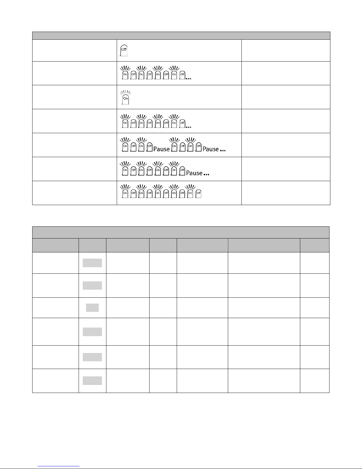
Status LED indications.
Static off.
Gates fully closed
Flashing slow 1 second on and 1
second off.
Until end of travel
Gates running normally.
Static on.
Gates open.
Flashing rapidly. 250ms on 250ms
off continuously.
One of the gates has collided with
an obstruction.
2 x 500ms flashes followed by a 2
second pause.
AC mains off. Restore AC as soon as
possible.
4 x 500ms flashes followed by a 2
second pause.
Battery low. Allow at least 8 – 10hr
uninterrupted charge before
checking again.
5 x 125ms second rapid flashes
each time a trigger is received.
.
A lock-out mode is active. Press and
release any holiday lock-out button
to deactivate.
Trouble shooting guide
Action Display Buzzer
Status
LED
Reason Resolve by
Referenc
e page
Any trigger.
hol
5 x 0.5 second
rapid.
Yes
Holiday lock-out
active.
Press and release any button
programmed into the
Holiday lock-out channel.
Page 20.
Any trigger.
par
5 x 0.5 second
rapid.
Yes
Party mode/auto-
close override
active.
Press and release any button
programmed into the
Holiday lock-out channel.
Page 21.
For 5 minutes
after any
operation.
ac
1 x 0.5 second
beep every 15
seconds.
Yes
Household VAC
mains failure.
Restore VAC mains supply as
soon as possible.
No user action.
System
automatically
tests.
bat
None Yes
Battery level low
under load.
Allow 8 – 10 hours
uninterrupted recharge. If
the battery level does not
recover, replace the battery.
Any trigger.
ref
Continuous
repetitive 1
second beeps.
No.
Motor position
reference out of
sync.
Complete the end of travel
reference routine.
Page 6.
Any trigger.
run
5 x 1 second
slow beeps.
No.
Runtime setup not
completed
properly.
Call your service
provider/installer.

Ver: 2015.001
23
Receiver user address log
Address
Channels
User identification Address
Channels
User identification
BT
PED
RLY
HOL
BT
PED
RLY
HOL
001 033 002 034 003 035 004 036 005 037 006 038 007 039 008 040 009 041 010 042
011 043 012 044 013 045 014 046
015 047 016 048 017 049 018 050 019 051 020 052 021 053 022 054 023 055 024 056 025 057 026 058 027 059
028 060 029 061 030 062 031 063
032 064

Ver: 2015.001
24
WARRANTY:
1. All goods manufactured by ET Systems (Pty) Ltd carry a 12 month factory warranty from date of invoice.
2. All goods are warranted to be free of faulty components and manufacturing defects.
3. Faulty goods will be repaired or replaced at the sole discretion of ET Systems (Pty) Ltd free of charge.
4. This warranty is subject to the goods being returned to the premises of ET Systems (Pty) Ltd.
5. The carriage of goods is for the customer’s account.
6. This warranty is only valid if the correct installation and application of goods, as laid out in the applicable documentation
accompanying said goods, is adhered to.
7. All warranty claims must be accompanied by the original invoice.
8. All claims made by the end user must be directed to their respective service provider/installer.
The following conditions will disqualify this product from the warranty as laid out above. These conditions are non- negotiable.
1. Any unauthorized non-manufacturer modifications to the product or components thereof.
2. Any modification to the installation methods described in the installation instructions.
3. Any application or use of the product other than the intended use and application described in the product documentation.
The following items are not included in the warranty or they carry a special warranty condition of their own.
1. The battery (Limited 6 month warranty)
2. The motor brushes.
3. Damage resultant of wind and other climatic influences such as lightning strikes.
4. Damage due to high voltage surges on the household mains or short circuiting of the gates to the electric fencing.
5. Damage due to infestation i.e. Ants nesting…
6. Water damage. It is the responsibility of the installer to ensure the product is installed in a location that is protected from water
ingress. The ingress protection rating is specified in the accompanying documentation. Housings that require that cable entries are
made by the installer do not carry an ex-factory ingress protection rating as it is the responsibility of the installer to seal the cable
entry points after installation of the cabling.
 Loading...