


ET DC BLUE ADVANCED INSTALLER 2012.025.12.05.2014
Domestic garag e d oor oper ator
Inst a ller Instructions
1
www.et.co.za

ET DC BLUE ADVANCED INSTALLER 2012.025.12.05.2014
TABLE OF CONTENTS
Page
Category
Introduction
3
Safe ty obligations and general warnings.
4
Technical specifications.
5
Component identific ation and descriptions.
Hardware installati on
6
In s talling the clu tch r eleas e m echanism o n the s ledg e/t r a veller .
7
Sectional overhead do or – Installing th e wall moun t bra c ke t.
7
Sectional overhead do or – Inst al l i ng the draw bar and hanging straps.
8
Sectional overhead do or – Installing the door mount brac ket.
8
Sectional overhead do or – Installing th e link arm.
8
Sectional overhead do or – Testing t he mechanical dri ve and linkage.
9
Trackless tip-up door – In s talling the wall moun t bra c ke t.
10
Trackless tip-up door – Installing the door mount bracket.
10
Trackless tip-up door – Installing the link arm and hanging straps.
10
Trackless tip-up door – Testing the m echanical dri ve and linkage.
11
B oth door typ es – Attaching the motor-head to the drawbar.
11
Both door types – Attaching the battery to the drawbar.
11
B oth door type s – Supplying household mains power to the motor-head.
Control card wiring and setup
12
Wiring of optional e x tra d e vic e s to the sy s te m.
13
Cont ro l panel dashboard and program ming menu summary. (How to navigate the me nu)
14
Programming - Open and closed limit setup and door load profiling.
15
Programming - Setting the obstruction force sensing, safety level.
16
Programming - Activatin g saf ety b eam mo de.
17
Programming - Act i vating and s elect ing the a u to -cl o se t im e.
18
Programming - Selecting an electric lock mode.
Recei ver p r ogr a mmi ng
19
Learn in g a n ew tran s mitte r b u tton code into t h e r eceiv er memo r y.
20
Clearing a single transmitter button co d e f r om t h e r eceiv er memo r y.
21
Master er a s in g all tra n s mitter bu tton codes f r om the receiver mem ory.
Q ui c k method of learn i ng a tr a n s mitte r b u tton code in to th e memory without ente r in g th e
pr o g r a mmi n g menu .
Operating
23
Bas ic o per at in g feat ur es us in g the (BT) bu tton tr ig g e r s .
25
Advanced operating features - Part y mode.
26
Advanced operating features - Holiday lock-ou t mode .
27
Advanced operating features - Strike lock mode.
28
Advanced operating features - Mag netic lock mod e.
29
Advanced operating features - Auto-close example.
29
Adv anced features - Sa f ety bea m exa mp le.
30
Adv anced features - Courtes y light oper ation.
Troubleshooting
31
Buz zer, courtesy light and display w arnings.
Warranty
32
Warranty terms and conditions.
22
2
www.et.co.za

ET DC BLUE ADVANCED INSTALLER 2012.025.12.05.2014
IMPORTANT WARNINGS TO THE INSTALLER AND GENERAL SAFETY OBLIGATIONS
• C au tion ! It is imp orta nt fo r p erso na l s afe ty to f ollow all th e in stru ction s ca refu lly . In corre ct insta ll at io n o r m isus e
may cause serious personal harm.
• Keep the instructions in a safe place for future reference.
• This product was designed and manufactured strictly for the use indicated in this documentation. Any other use
not expressly indicated in this documentation, may damage the product and/or be a source of danger.
• We accep t n o respon sibility due to improp er use or in correct install ation of this product.
• We will n ot ac cep t resp on sib ility if th e pr inc iples of g ood work ma n sh ip are d isreg ar ded b y th e in sta ller. T he
co n str u ctio n o f th e d oo r mu s t b e so u n d a n d au to m a tab l e. It is th e res p on s ib ilit y o f th e in sta l ler to e n su r e that all
mountings to the door are sufficient to withstand the necessary forces in cases of overload.
• It is highly recommended that a set of safety infra-red beams be used in conjunction with this product.
• Over and ab ove the recommen dation to use safety infra-re d b ea ms with th is pro du ct it is m an d ator y to in stall
an d use a sa fety beam set when u sing the automatic closing feature.
• We accep t n o respon sibility regarding sa fety and correct operation of the automa tion if other man ufacturer’s
equipment is added to this product.
• Do n ot make any modifica tions or alterat ions to this product.
• Anything other than expressly provided for in these instructions is not permitted.
• Prior to inst allation:
o The door must be balanced correctly to the tensioning system. When operated by hand the door
should be free of hindrance and easily moved. When left at any position in its travel, the door should
ne ith er rise no r fa ll. If th e doo r d oes rise o r fa ll, re-balance the tensioning system. (Tensioning should only
be carried out by a qua lified a nd experienced person)
o The do or materia l must be sound and whole. Ensure the areas where the operator attaches h ave been
re-enforced . The door ha rdw a re m ust be in good servicea ble con d itio n.
o En sure the wa ll ab ove the door is soun d and stron g enoug h to a llow proper fixing of th e operator. If
ne ce ssary use th rough bolts and/or cross brac e plate to spread th e load . (Ty pically on cin der brick or
h ollow wa lls)
o The DC Blue Advan ce d is de sign ed f or w eath erp roo f a pp lica tion s on ly . Ins tall in com p letely wa lled an d
roofed garages only.
o Ensure the area of installation is not subject to explosive hazards. There should be no volatile ga sses or
fum es as these ca n present a serious safety hazard.
o Th e DC B lue Ad va nc ed is d esig n ed to b e us ed in low tra ffic ap p lication s o nly . Do n ot in sta ll on do ors
u sed fo r m u lti pa rkin g ga ra ges like off ice p ar ks o r a pa rtm en t bloc ks w ith a sing le en tran ce .
o The DC Blue Advanced is su p plied with a se ale d 15A sa fety plug on lead for use in a n electrica l code
of prac tice approved plug poin t. Do no t e x tend, m odify or rep lace the plug lead u nless duly qualified
as an electrician. Before installing the unit, ensure the mains supply is switched off.
o It i s th e resp on sib ility of the in stalle r to a scer tai n th at th e d esig na ted p er son s (in clu din g c hild re n)
intended to u se the system , do not suffer red u ced physical sensory or mental capabilities , or lack o f
experience and knowledge, unless they have been g iven su p ervision or instruction concerning the use
of the sy stem by a person responsible for their safety.
o Th e d rive ma y n ot be insta lled on a d oor in co rpo ra ting a wick et do or, u n less th e drive is d isab led by the
release of the wicket door. (Wicket door :- A pedestrian door within the main door)
3
www.et.co.za
Cont.…..

ET DC BLUE ADVANCED INSTALLER 2012.025.12.05.2014
Sy ste m s a c ce pts n o r es p on s ib ili ty f o r th e s a fe ty a n d co rr ec t op e ra tion o f th e a u to ma ti on s y ste m i f a n y
TE CH N ICAL S PE CI FI CA TION S
Primary power supply
220 – 240Vac @ 50hz
Power consu mption
120W peak @ ( 220 -240vac)
Motor voltage
24V dc
Maximum operatio ns per day
50 ful l cycl es per 24h rs @ a r ate of Max. 2 p er ho ur
Tra vel l er sp eed*
8m/min
Oper ating temp er a ture r ang e
-10 to 50° C (14F to 122F)
Anti-crushi ng safety sensing
Yes - Ele c tron ic digital prof ilin g
Auxiliary supply output
24Vdc @ 250mA peak or 150mA continuous
Rated battery charging vo l t age
27.5Vdc
Bu ilt in re c e ive r format
ET BLU MIX © enhanced ro lling code.
Receiver frequency
433.92Mhz
Memory
EEPROM
One piece trackl es s ti p -up or mu ltiple p an e l se c tiona l
overhead doors
Drawbar options(Ex-stock)
2.2m or 3.2m or 3.7m
Applicable door sizes
<13m²
• Installation:
o Rem ove all cables, la tch es/locks or catches n ot n ecessa ry for au tom ation.
o Ensure the wo rk in g area is clear of obstruc tions and ob stacles.
o Install the d oor sticker depicting the safety reverse test and keep ing door area clear. Th is sticker shou ld
be fixed to the inside surface of the door or near any permanent door control switches such as a wall
con so le if in stalle d.
o The emergen cy release cord m ust be insta lled wh ere it is no h igh er tha n 1. 8m f rom th e flo or level.
o An y ad dition a l fixed d oor co ntro l switch es s uc h a s wall c on soles , if ins talled , m u st be a t a h eig ht of a t
least 1,5m, within clear sight of the door and away from any moving components of the system.
o Do not substitute any component of DC Blue Advanced with any other manufacturer’s part. ET
of these p oin ts a re ign ored .
• Afte r I n stallation: I t is the responsibility of the installer to ensure the user:
o Is proficient in th e use of th e man ual emergen cy release mecha nism.
o Is issued with the documentation accompanying this product.
o Understands that th e door may not be operated out of clea r sig ht.
o Ensures that children are kept clear of the door area and that children do not play with the remote
transmitters.
o I s ins tru c ted n o t to a tte m p t to r ep a ir o r a d ju s t th e a u to m a tion s y ste m a n d to b e a w ar e of th e d a n g er
of continuing to use the automation system in an unsafe condition before a service provider attends to
it.
o Is proficient in testing the unit’s safety obstruction sensing system by means of placing a 40mm high
object (wood en block) b elow the d oor in the closed p osition. On contact w ith th e ob je ct th e u n it mu s t
reverse the d oor away an d back to the op en position.
Applicable doo r t ypes
* Based on t he assumption t hat t he doo r i s bal anced correctly and mov i ng freely.
4
www.et.co.za

ET DC BLUE ADVANCED INSTALLER 2012.025.12.05.2014
Diagram
Diagram
1
Wall mount bracket
1
20
Nylock nuts M8
8 2 Pivot pin 8mm x 90mm
1
21
Flat washers M6
6 3 C otter p ins 1.8m m x 35mm
3
22
C o a c h screws 8 x 60mm
2
4
Door moun t bracket
1
23
C o a c h screws 8 x 40mm
6 5 Straig ht lin k a rm
1
24
Wa ll plugs 10m m
2 6 C urved lin k arm extension
1
25
Warning sticker
1 7 Em ergency release a ssembly
1
26
24Vdc 3. 5A/h Ba ttery (Optional extra)
1
Round he ad mac hi ne s c r e ws M 6 x
Em ergency release cord 1. 1m with
warning tag
Em ergency release cord p lastic
knob/handle
11
Pivot p ins 8mm x 25mm
2
30
Drawbar
1
Hanging strap drawbar attachment
bracket
Drawbar spring dampener and shock
absorber
32
Battery connection beneath dust
cover sticker
1
E-Coms connection plug with dust
15
Hanging straps 1m
3
34
Drawbar back-end
1
16
Ma chine bolts 10m m head M6 x 15mm
2
35
Splined sprocket with chain
1
17
Ma chine bolts 14m m head M8 x 15mm
8
36
Household mains cord 1.5m
1
Au xilia ries c on ne ctio n plu g w ith d us t
19
Nylock nuts M6
6
38
C over screws
4
COMPONE NT IDENTIFICATION AND DESCRIPTIONS
number
8
9
20mm
Description Qty
4
1
number
27 Motor-head 1
28 Control panel dashboard 1
Description Qty
10
12
13 Drawbar brackets 3
14 Battery straps 2
18 Machine nuts M6 4
1
1
5
www.et.co.za
29 C ou rtesy ligh t diffu se r len s 1
31
33
37
cover 1
cover 1
1

ET DC BLUE ADVANCED INSTALLER 2012.025.12.05.2014
INSTALLING THE MANUAL OVERRIDE CLUTCH ASSEMBLY ONTO THE SLEDGE/TRAVELLER
! CAUTION
TO DI SENGAGE AND
TO RE-ENGAGE AND
Install the manual ove rride label as shown here.
HARDWARE INSTALLATION
(See pa ge 5 for co mp onen t identificatio n )
The di agrams be low show how to install the manu al ove rr ide clutch assembly onto the
sl edg e tr av el ler . E nsu re t he 4 m ac hin e scr ew s are secu rel y fa st ened. D o th is p ri o r t o
installin g th e d ra wbar.
MOVE DOOR
MANUALLY:
Warning! Door may plummet
closed when released.
W hile pulling the emergency
release cord downwar d , move
the door open or closed by
hand.
LOCK DOOR BACK
ONTO DRI VE:
Let t he cord g o a nd move
door open or closed unt il the
sledge/traveller locks back
onto the chain d rive.
6
www.et.co.za

ET DC BLUE ADVANCED INSTALLER 2012.025.12.05.2014
INSTALLING THE WALL MOUNT B RACKET (See page 5 for c om p onen t i d entificati on)
INSTALLING THE DRAWBAR AND HANGING STRAPS (See pa ge 5 for component i d en ti fi ca ti on)
HARDWARE INSTALLATION
St and ar d Sing le Tr ack or Doubl e Tr ack Sectiona l Gar age Door M et h od
The diagram be low shows how to determine the mounting height and position of the wall mount bracket,
in the case o f a standard single track or double track overhead sectio nal g arage doo r system.
NB!!! The wall mount bracket is one of the components that take the majority of the load in a garage door
automa t ion sys t em . Extra care needs to be tak en to ensure the br acket is securely fa stened an d th at
wha t ev er t he bracket is fa stened to, can withsta n d force equal to the force of t h e door wh en t he sp ring
balancing of the door is removed (snapped)
7
www.et.co.za

ET DC BLUE ADVANCED INSTALLER 2012.025.12.05.2014
TESTING THE MECHANICAL DRIVE AND LINKAGE
INSTALLING THE DOOR MOUNT BRACKET (See pa ge 5 for co mp onent i dent ificati on)
INSTALLING THE LINK ARM (See pag e 5 fo r compo nent iden ti ficatio n )
Mount t he door m o unt bracket o n the i nside fascia of the door as shown be low. Kee p it as in line as
possible with the t o p guide rollers and centred from side to side of the door.
NB!!! The door mount bracket is one of the components that will take the majority of the load in a garage
door a u tomat ion sys t em . Extra care needs to be tak en to ensure that the bracket is secu rely fas t en ed.
Wh atever th e bra cket is fa stened to, must al so withstand a f orce eq ual to the for ce of the door wh en t he
spring balancing of the do o r is rem o v ed. For exam ple if a balanc ing spring snaps.
Clo se the door fully. Install the curved li nk arm ext ension in the door m o unt bracket using one of the cott er
pins and 25mm long pivot pin s s u pp lie d . Ne x t usin g the othe r 25mm long p ivot pin an d cotte r pin , install
t h e s tra ight link ar m in the tra vel ler/ s ledge th at ha s b een moved a ll the way to the f r ont o f the d r awba r .
F in a lly bolt th e cu r ve d e x tens ion to th e str ai gh t l in k a r m, s o th a t the two c ombi n e d f o rm t h e s a me a n gle a s
shown below.
T hi s method provides be tter positive locking of the door in the clos e d pos ition tha n the c ommonly used 45 ⁰
angled link arm. This method also produces less backward force on the ge arbox whe n trying to c ompress
the seal at the bottom of the door as the downward force is generated by the link arm c amming up and
ov er the door.
It is now possible to test the mechanic al moveme nt of the door with the link arm attache d and the
sledge/traveller engaged onto the chain drive. The movement of the door throughout its travel should be
approximately the same while pulling the chain around the drawbar, as it is when the chain is not
engaged.
If satisfied that the drawbar is not causing unne c e ssary drag or hindrance to the door movement, then go
ahead and att ach the mo t o r-head to the drawbar. (Page 11)
8
www.et.co.za

ET DC BLUE ADVANCED INSTALLER 2012.025.12.05.2014
INSTALLING THE WALL MOUNT B RACKET (See page 5 for c om p onen t i d entificati on)
HARDWARE INSTALLATION
Tra ckl ess tip-up d oor
From the top edge of the door in the closed position, measure 275 – 300mm per p en dicu lar t o the to p
edge of the door. Install the wall mount bracket at this height where it is positioned above the centre of
the door as show n in the diagram belo w.
NB!!! The wall mount bracket is one of the components that will take the majority of the load in a garage
door a u tomat ion sys t em . Extra care need s t o be ta ken to en sure th at th e br acket is secu rely fas t ened.
Whatever the bracket is fastened to, must also withstand a f orce eq u al to t he force of t he door when th e
spring balancing of the do o r is rem o v ed. For exam ple if a balanc ing spring snaps.
9
www.et.co.za

ET DC BLUE ADVANCED INSTALLER 2012.025.12.05.2014
INSTALLING THE DOOR MOUNT BRACKET (See page 5 fo r co mp onent i d entificati on)
INSTALLING THE LINK ARM AND HANGING STRAPS (See p age 5 fo r co mponen t i d en ti fi ca ti on)
TESTING THE MECHANICAL DRIVE AND LINKAGE
Mount the door mount bracket on the top edge of the door, where it is centred from side to side of the
door.
NB!!! The door mount bracket is one of the components that will take the majority of the load in a garage
door a u tomat ion sys t em . Extra care need s t o be ta ken to en sure that t h e br acket i s secu rely f ast en ed.
Wh atever th e bra cket is fa stened to, must al so withstand a f orce eq ual to the for ce of the door wh en t he
spring balancing of the do o r is rem o v e d. Fo r exam ple if a balanc ing spring snaps.
Install the front e nd of the drawbar in the wall mount bracket using the 90mm pivot pin and one of the
cott er pins. Raise the draw bar up and out of the w ay of the door. Install the link arm into both the
sledge/traveller and door mount brac ket using the 25mm pivot pins and re maining two c otter pins.
Prepare and inst al l the hanging straps so that w hen the door is in the full open posit io n, the l i nk arm lays
180⁰ to the door . Do not use the cu rve d link a rm e x te n sion in this ty pe of installation . The diagr am be low
shows the final position of the drawbar when installed and examples of how to pre pare the hanging
straps.
It is now possible to test the mechanic al moveme nt of the door with the link arm attache d and the
sledge/traveller engaged onto the chain drive. The movement of the door throughout its travel should be
appro ximately the same w hile pulling the chain around the drawbar, as it is when the chain is not
engaged.
If satisfied that the draw bar is not causing unnecessary drag or hindrance to the door movement, then go
ahead and att ach the mo t o r-head to the drawbar. (Page 11)
10
www.et.co.za

ET DC BLUE ADVANCED INSTALLER 2012.025.12.05.2014
ATTACHING THE MOTOR-HEAD TO THE DRAWBAR (See page 5 fo r compo nent iden ti ficatio n )
ATTACHING THE BATTERY TO THE DRAWBAR (See pag e 5 f or com pon ent iden ti f ication)
SUPPLYING HOUSEHOLD POWER TO THE MOT OR -HEAD
Insert the splined motor drive shaft into the splined sprocket at the back-end of the drawbar. Swivel the
motor-he ad around so that the motor mounting straps are able to fit over the drawbar and onto the
mounting studs on the motor-he ad. Fasten the drawbar mounting straps onto the motor-head using the 4
M6 machine nuts and M6 flat washers.
Making use of the extended length m o unt i ng straps and 4 of the M6 Nylock nuts fasten t he batt ery atop
t h e d rawb a r as s hown bel ow. Remove the sti cker cov er ing the battery plu g so cket on the mo to r -head
an d ins er t t h e battery l ea d pl ug. Th e ba ttery plu g is m oulded in such a way as to only be i nserted i n one
direction. Ensure the plug is in firmly.
The DC BLU E A DVA NCED © comes supplied with an IEC and SA NS compliant 22 0Vac po wer cord, 1,5m in
length. Plug t he s eal ed no n-serviceable 3 pi n 15Amp plug into a certified 15Amp plug socket that is
installed outside of the workin gs of the gar ag e door syste m, yet still withi n reach of the power cord. E n s ure
the there is no strai n on the cord once insta ll ed. Also ensure that nothing will catch or snag the powe r
co r d when the g a r age d oor is movin g or when people or car s p a s s belo w th e s ystem.
11
www.et.co.za

ET DC BLUE ADVANCED INSTALLER 2012.025.12.05.2014
OPTIONAL EXTRA DEVICES WIRING CONNECTIONS
12
www.et.co.za

ET DC BLUE ADVANCED INSTALLER 2012.025.12.05.2014
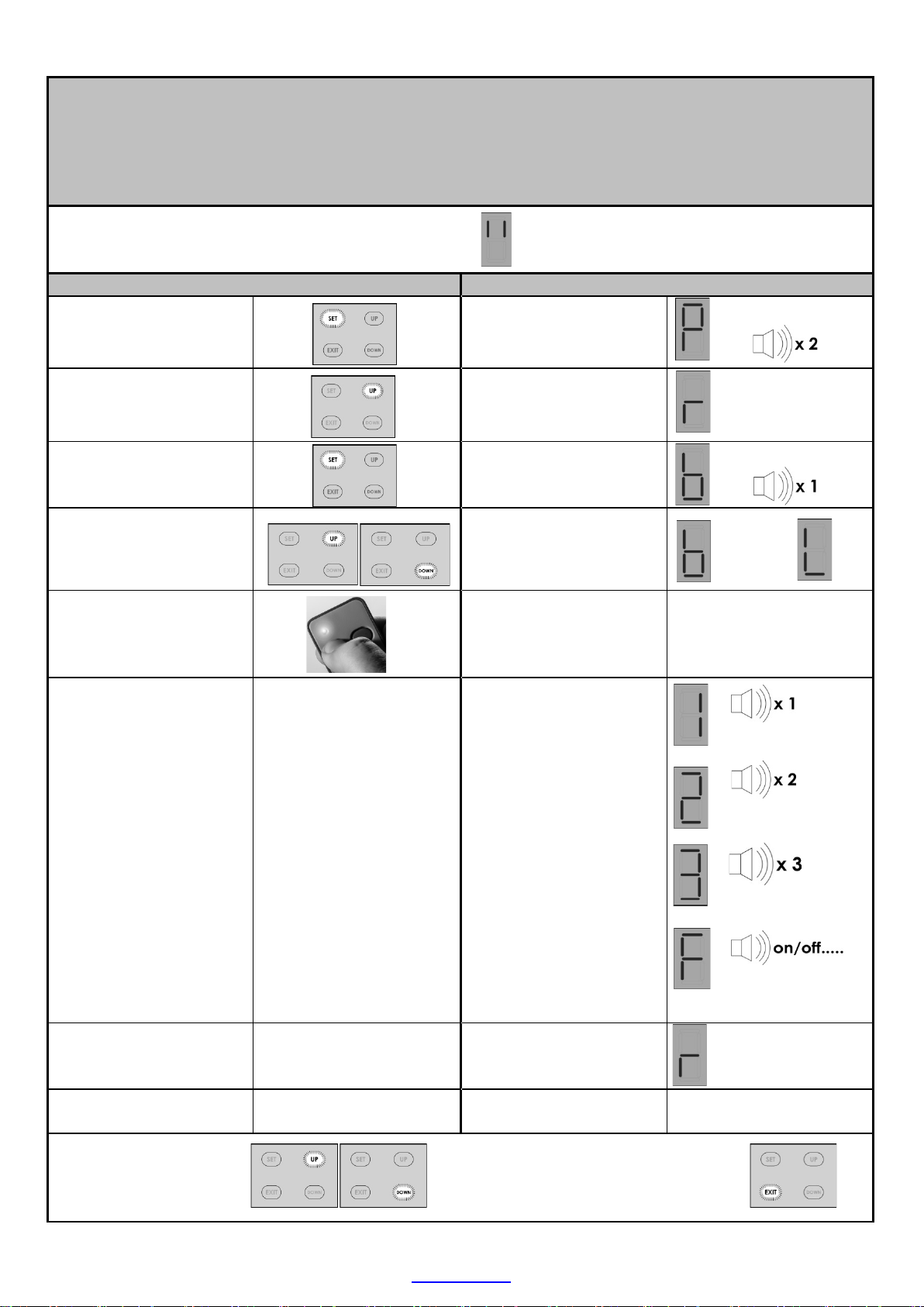
NOTE! Before attempting to execute the instructions, read the
EXIT BUTTON
CONTROL PANEL DASHBOARD AND PROGRAMMING MENU SUMMA RY
(How to n avi gat e t he menu opt ion s )
co mplet e instructio n ta ble, fo r a set up o ptio n . Some s teps r eq uir e a
res po nse b efo re a saf ety ti m eou t expi res a nd yo u ma y st il l be
rea d ing the next step wh en the timeout ex p ires .
• To ent er the Programming menu from Standby mode, press and
hold the “SET ” butt on until the buzz er b eeps twice.
• O nc e in the Programming menu, use t he up and down butt o ns to
scroll between options.
• For further instru ctio n on changing setti ngs, refer t o the instructio n
t a bles on the page indicated for each o pt i o n.
• To exit a setup optio n
without changi ng the
current setting for that
option, pre ss an d
release the “EXIT”
button. T h e men u will
exi t ba ck one level.
• Note 1: If the “EXIT”
bu tton is pressed
bef or e com p let in g
the Limit and door
profile setup, no limit
and door profile
se ttings will be in
memory. You must
complete this setup
to operate the door.
(See “P” symbol
disp laye d in the
Trouble shoot ing
table on page 31)
13
www.et.co.za

ET DC BLUE ADVANCED INSTALLER 2012.025.12.05.2014
PROGRAMMING
Open and cl osed limit position setup and door load profili ng.
Action
Response
Displa y be gins f las h i ng “ P”
confirm limit set up mode
Buzzer beeps once a nd
Press and hold the UP
When satisfied the door is
bu tton to adv a nc e to the
The b u zz er b eeps o n ce
closed lim it position must
button to lower the door
bu tton to adv a nc e to the
will bee p in t ermittently as
c on tr ol r eturns to the ma in
Scroll up o r do wn
option.
OR
Pr es s and relea s e E XIT t o
From Standby M ode
To enter th e pro gra m
menu. Press and hold SET
butt on until buz z er beeps
twice.
Scroll up with the UP
butt o n unt i l “ L” flashes.
Pr es s and relea s e SE T
button to begin limit
setup.
button to raise the door to
t h e r equi red o pen
position.
Fine tune using the UP
and DOWN but tons.
in the cor rect open
posi tion , pr ess th e SET
an d buz zer b eeps t wice
to confirm the main
pr ogr am menu is a cti ve.
Disp l ay flashes “L” t o
is s elect ed .
“O” displ a ys to indicate
open limit position must
be s et.
The “n” symbol displa y s as
the door opens.
The “ n” and “ u” symbo l s
confirm the doo r direction
w hi l e fine tuning.
and the “C” symbol
displays to indicate the
or
close limit setup.
Press and hold the DOWN
t o t h e r equi red cl osed
position.
Fine tune using the UP
and DOWN but tons.
When satisfied the door is
in the cor rect clo s ed
posi tion , pr ess th e SET
automatic door load
profiling stage.
be s et.
The “u” sy mbol displays as
the door closes.
The “ n” and “ u” symbo l s
confirm the door dir e c t i o n
w hi l e fine tuning.
Door opens and closes
again.
The di spl ay confirms the
direction and t he buzzer
the m otor runs.
W h en compl ete, the
program menu.
Display = Flashing “P ” and
bu zz er b eeps o n ce.
or
to next program
14
www.et.co.za
return to Standby mode.
See Note 1 on page 13!!!

SETTING THE OBSTRUCTION FORCE SENSING, SAFETY LEVEL.
Def ault level - 3
Action
Response
To enter th e Progr a m
Displa y be gins f las h i ng “ P”
Pr es s and relea s e the SE T
To
Scroll up o r do wn
option.
OR
Pr es s and relea s e EXI T to
menu. Press and hold SET
butt on until buz z er beeps
twice.
ET DC BLUE ADVANCED INSTALLER 2012.025.12.05.2014
From Standby M ode
an d buz zer b eeps t wice
to confirm the mai n
pr ogr am menu is a cti ve.
Scroll up with the UP
butt o n unt i l “ F” flashes.
Pr es s and relea s e SE T
button to enter safety
fo rce set up.
Pr es s and relea s e the UP
or DOWN buttons to scroll
to the desired safety force
level. (1-9)
button to save the new
setting to memory and
exit back to the main
program menu.
Disp l ay flashes “F” t o
confirm safety force setup
m ode is select ed .
Buzzer beeps once a nd
cur r ent s afet y force l evel
is displayed. (1-9)
1 = most sensitiv e to
resistance in movemen t of
the door.
9 = leas t sen s itive to
resistance in movemen t of
the door.
The b u zz er b eeps o n ce
and the display returns to
flashing “ P”.
to next program
In the case of the door being resisted physically or obstructed while opening.
• The motor will stop r un n ing,
• The b uzzer will beep once an d oper ator r ever ts to st andby mode.
• On the next BT button trig ge r the motor will sta rt c los ing the d oor.
In the case of the door being resisted physically or obstructed w h ile closin g .
• The motor will stop runn ing,
• The b uzzer will beep once as the motor immedi ately b egin s o peni n g t h e d oo r on ce agai n.
• On rea ch ing t he op en pos it ion the oper ator r ever ts to st andby mode.
• On the next BT button trigge r the motor will begin the door c los in g.
return to Standby mode.
SAFETY OBSTRUCTION SENSING IN ACTION:
15
www.et.co.za

ET DC BLUE ADVANCED INSTALLER 2012.025.12.05.2014
ACTIVATING SAFETY BEAM MODE.
Action
Response
set up by scrolling up w ith
OR
Scroll up o r do wn
option.
OR
Pr es s and relea s e EXI T to
Default – Off (Disabled)
NB! When auto-clo s e mode i s a c tiva ted, the saf ety beam mo d e a utomatica ll y becom es active.
This is mandato ry as auto-close mo d e ma y n ever be used wi thout a set o f s afet y beam s installed.
With auto-close a ctive, saf ety beam setup mode i s n o l ong er av a ilabl e in the s etup menu.
From Standby M ode
To enter the Pro gra m
menu. Press and ho l d SET
butt on unt i l buz z er beeps
twice.
Select sa fet y b eam s
the UP button until “b”
flashes.
Pr ess a nd rel ease SE T
button to enter safety
bea m setup.
Pr es s and releas e t h e UP
button for On or DOWN
but ton fo r Off selecti o n .
Pr es s and releas e t h e SE T
button to save the new
setting to memory and
exit back to the main
program menu.
Display begins flashing
“ P ” a n d bu zzer beeps
twice to confirm the
mai n pro gram m enu i s
active.
Disp l ay fl ashes “ b” t o
co n f irm sa f ety b ea m
setup mo d e is s elected.
Buzzer beeps o n ce and
current beam status i s
displayed.
0 = Off and 1 = On
0 = Off ( D i sa bled)
1 = O n (Activ e )
The bu zzer beeps o n ce
and the display returns to
flashing “ P”.
to next program
return to Standby mode.
16
www.et.co.za

ET DC BLUE ADVANCED INSTALLER 2012.025.12.05.2014
ACTIVATING THE AUTO-CLOSE MODE AND SELECTING AN AUTO-CLOSE TIME.
Action
Response
or DO WN buttons to s croll
To
Scroll up o r do wn
option.
OR
Pr es s and relea s e EXI T to
Default – Off
NB! When auto-clo s e mode i s a c tiva ted, the saf ety beam mo d e a utomatica ll y becom es active.
This is mandato ry as auto-close mo d e ma y n ever be used wi thout a set o f s afet y beam s installed.
With auto-close a ctive, saf ety beam setup mode i s n o l ong er av a ilabl e in the s etup menu.
From Standby M ode
To enter the Pro gra m
menu. Press and ho l d SET
butt on unt i l buz z er beeps
twice.
Select a ut o-cl os e set up
by scrolling up with the
UP button until “A”
flashes.
Pr ess a nd rel ease SE T
button to enter auto-
clo se s etu p.
Pr es s and releas e t h e UP
t o t h e d es ired s ett ing .
Pr es s and releas e t h e SE T
button to save the new
setting to memory and
exit back to the main
program menu.
Display begins flashing
“ P ” a n d bu zzer beeps
twice to confirm the
main program menu is
active.
Disp lay flashes “ A” to
co n f irm au to-clos e s etup
m ode is select ed .
Buzzer beeps o n ce and
current aut o-close status
is displayed.
0 = Off. 5 = 50 sec.
1 = 10sec. 6 = 60sec.
2 = 20sec. 7 = 70sec.
3 = 30sec. 8 = 80sec.
4 = 40sec. 9 = 90sec.
The bu zzer beeps once
and the display returns to
flashing “ P”.
to next program
17
www.et.co.za
return to Standby mode.

ET DC BLUE ADVANCED INSTALLER 2012.025.12.05.2014
SELECTING A LOCK MODE.
Default – Off
0861 109 9238 or support@et.co.za
Action
Response
main program menu is
button to save the new
To
Scroll up o r do wn
option.
OR
Pr es s and relea s e EXI T to
NB!! The “E-Coms” output on the control card is d es ignated t o be used wit h a n “E -Com s” Relay m odule,
w hen using any electric lock. These modules are only available via ET Systems.
For further instructi o ns on the E-C om s relay module, consult the instruct ions included wit h it.
For assi stance t he product suppo rt department can be contacted on:
In s t rike lock mode, the lo ck rel ay w ill energis e 0 .5sec before t he m ot or b eg ins open ing a n d rel ease
ag ain 0 .5sec after t he m ot or has begun moving. (Tot al 1sec. pulse length)
In ma gnet ic lock mode, t he lock rela y wi ll en ergise, 0.5sec bef ore t h e mo to r st arts opening and 5 s econds
later, the lo ck relay module switches off again. (Total 5sec. pulse length)
To enter the Pro gra m
menu. Press and ho l d
SET butt o n unt i l buz zer
beep s t w ice.
Select lo ck setup b y
scrolling up with the UP
button until “” flash es.
Pr ess a nd rel ease SE T
button to enter lock
setup.
Pr es s and releas e t h e UP
or DOWN buttons to
scroll to the desired
set ting.
From Standby M ode
Display begins flashing
“ P ” a n d bu zzer beeps
twice to confirm the
active.
Disp l ay fl ashes “ ” t o
co n f irm lock s etup
m ode is select ed .
Buzzer beeps o n ce and
current lock st a t u s i s
displayed.
0 = Off.
1 = Strike lock.
2 = Magnetic lock.
Pr es s and releas e t h e SE T
setting to memory and
exit back to the main
program menu.
to next program
The bu zzer beeps o n ce
and the display returns
to flashi ng “ P”.
return to Standby mode.
18
www.et.co.za
ET DC BLUE ADVANCED INSTALLER 2012.025.12.05.2014
LEARNING A T R ANSM IT T ER CODE IN THE RECEIVER MEMORY.
Action
Response
To enter the P r ogr am
twice.
Displa y be gins f las h i n g “P”
pr ogr am menu is a cti ve.
Disp l ay flashes “r ” t o
selected.
“b” for (BT) is displayed.
or DO WN b u tt ons to sc roll
.
LE D o n remote tr ans mitter
“1” on display and 1 be e p
Release the remo te
Me mo ry f ull
Code already in
Successful
Unsuccessful
Scroll up o r do wn
option.
OR
Pr es s and relea s e EXI T to
Max users (BT) button trigger chann el = 35 user codes
Max users (LT) cou rtesy ligh t t rigger ch ann el = 5 user codes
NB!! The built in receiver will o nly work with t he ET BLU MIX © enhanced roll i ng code or ET BLUE ro l l ing code
transmitters.
From Standby M ode
menu. Press and hold SET
butt on unt i l buz z er beeps
Select receiv er set up b y
scrolling up with the UP
butt o n unt i l “ r” flashes.
Pr es s and relea s e SE T
bu tt on to en ter r eceiv er
programming.
Pr es s and relea s e the UP
to the c hanne l the remot e
button must be learnt into
Press and hold desired
remote button.
While still holding the
desired remote butt on,
press a n d r eleas e the
“SET” button.
an d buz zer b eeps t wice
to confirm the main
co n f irm receiv er
programming menu is
Buzzer beeps once a nd
b = (BT) button trigger
channel.
L = (LT) Courtesy light
trig ger channel.
illuminates.
= user code successfully
learnt.
“2” on display and 2
beep s = user code
alrea d y i n the r eceiv er
memory.
“3” on display and 3
beeps = Unsuccessful
beca u s e no code wa s
seen within 4 s ec of the
SET b u tt on b eing press ed .
Mandatory timeout.
“F” on display and
mul t ipl e rapid beeps =
Memory full
The di spl ay returns to
flashing “r”. Receiver
programming menu.
or
memory
button
to next program
return to Standby mode.
19
www.et.co.za

ET DC BLUE ADVANCED INSTALLER 2012.025.12.05.2014
CLEARING A SINGLE TRANSM IT T ER BUTTON CODE FROM THE RECEIVER MEMORY.
again.
Action
Response
Display begins flashing
active.
scroll to t he “C” o ption.
Release the r emote
button
Disp lay rev er ts b ack to
recei v er set up m enu .
Unsuccessful
Scroll up o r do wn
option.
OR
Pr es s and relea s e EXI T to
Thi s can on ly be completed i f the remot e con t rol th at must b e erased is presen t .
If the rem ot e control tha t must be r emov ed is mi s s ing or u n obtaina b le, then a m a s ter erase p roced ure
(Pag e 21 ) m ust be performed and the remaining, valid user codes must all be learnt i nt o th e memo r y once
From Standby M ode
To enter the Pro gra m
menu. Press and ho l d SET
butt on until buz z er beeps
twice.
Select receiver setup by
scrolling up with the UP
butt o n unt i l “ r” flashes.
Pr ess a nd rel ease SE T
bu tt on to en ter r eceiv er
setup.
Pr es s and releas e t h e UP
or DOWN buttons to
Press and hold desired
remote button to be
era sed.
While still holding the
desired but ton, press
an d relea s e SET bu tt on.
“ P ” a n d bu zzer beeps
twice to confirm t he
main program menu is
Disp l ay fl ashes “ r” t o
co n f irm receiv er setup
m ode is select ed .
Buzzer beeps o n ce and
“b” is displayed.
“C” is displayed.
LE D on r emote
transm it ter illuminates.
“0” on display and 1
beep = user co de
successfully erased.
“3” on display and 3
beeps = Unsuccessful
beca u s e no co d e was
seen wi thin 4 s ec of the
SET button being
pressed.
Mandatory timeout.
to next program
flashing “r” to indicate
you hav e ret urn ed t o t h e
return to Standby mode.
20
www.et.co.za

ET DC BLUE ADVANCED INSTALLER 2012.025.12.05.2014
Action
Response
Display begins flashing
active.
button to scroll to the “E”
Display go es blank and
commenced.
Disp lay stays “0” and
era s e i s com plete.
Scroll up o r do wn
option.
OR
Pr es s and relea s e EXI T to
MASTER ER ASIN G ALL T RA NSMI T TER B UTTON CODES FROM THE MEMORY.
From Standby M ode
To enter the Pro gra m
menu. Press and ho l d SET
butt on unt i l buz z er beeps
twice.
Select receiver setup by
scrolling up with the UP
butt o n unt i l “ r” flashes.
Pr es s and releas e SET
bu tt on to en ter r eceiv er
setup.
Pr ess a nd rel ease t h e UP
option.
Pr ess a nd h old SET
butt o n and do no t
release.
Wh ile st ill h oldin g the SET
button.
Pr ess a nd releas e UP
button to start master
erase. Rel ease b ot h
buttons once beeps
begin.
“ P ” a n d bu zzer beeps
twice to confirm the
main program menu is
Disp l ay fl ashes “ r” t o
co n f irm receiv er setup
m ode is select ed .
Buzzer beeps o n ce and
“b” is displayed.
“E” is displayed.
Disp l ay fl ashes “ E” and
bu zz er b eeps
intermittently to w arn
t h at ma s ter er a s e is
about t o begin.
NB! Pressing and hol di ng
EXIT at this point will
ab ort t h e ma s ter er a s e.
Master era s e routin e is
running. Wait.
Master era s e routin e is
running. Continue
waiting.
to next program
bu zz er s ilen ces to
indi cate er ase h as
bu zz er emi ts 1 lo n g
beep , to indicate Master
Disp lay rev er ts b ack to
flashing “r” to indicate
you ha ve retur ned to t h e
recei v er set up up m en u.
return to Standby mode.
21
www.et.co.za

ET DC BLUE ADVANCED INSTALLER 2012.025.12.05.2014
A QUICK METHOD OF LEARNING A TRANSMITTER BUTTON CODE INTO THE RECEIVER MEMORY WITHOUT
Action
Response
“1” on display and 1
Memory full
Release bot h the r emote
button and “SET” button
Me mo ry f ull
Code already in
memory
Successful
Unsuccessful
ENTERING THE PROGRAMMING MENU.
Max us ers ( BT) but t on t rigger chan n el = 35 u ser codes
NB!! No rem o t e codes can be learnt into t he (LT) court esy l i ght channel t hi s way.
Door mus t be closed Door closed
Press and ho ld the “Up”
butt on unt i l buz z er beeps
and di spl a y show s “ b ”.
Buzzer beeps o n ce and
displ a y show s “ b ”
Press and hold required
remote button.
Pr ess a nd rel ease t h e
“SET” button.
LE D on r emote
transm it ter rem ains lit.
beep = user co de
successfully registered.
“2” on display and 2
beep s = user cod e
alrea d y in t he recei ver
memory.
“3” on display and 3
beeps = Unsuccessful
beca u s e no co d e was
seen wi thin 4 s ec of the
“SET” button being
Mandatory timeout.
“F” on display and
mul t ipl e rapid beeps =
pressed.
Disp lay rev er ts b ack
standby mode “II”
22
www.et.co.za
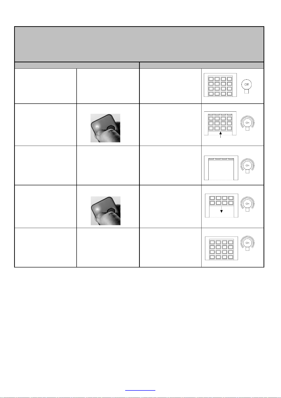
BASIC OPERATING FEATURES
Exampl e 1. Simply opening the door fully and closing the door again fully.
Action
Response
Door stops in the closed
Press and release either
the remote button
trig ger or t he hardw i red
trigger.
ET DC BLUE ADVANCED INSTALLER 2012.025.12.05.2014
Bas ic o pen and close t ri g g ers usi ng the (BT) button trigger.
Door in the closed
position.
Co ur t esy l i g ht off.
Doo r begins o pening
and courtesy lig ht
sw itches on.
Wait fo r do o r t o reach
the full open position.
Press and release either
the remote button
trig ger or t he hardw i red
trigger.
Wait fo r do o r t o reach
the closed position.
Do o r stops and wai t s i n
the open posit i o n.
Courtesy light remains
on for a furt her 3
minutes.
Doo r begins closi ng and
if the courtesy li g ht had
previo usly tim ed out and
switche d off, it will switc h
on agai n for three
minutes.
position. Light remains
on unt il t hree minute
t im er has ex p ired .
23
www.et.co.za
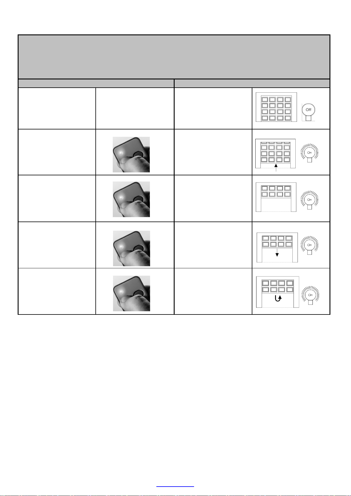
BASIC OPERATING FEATURES
Exampl e 2. Using the (BT) button trigger input while t he door is running.
Action
Response
Press
release
Door stops and waits for
next instruction. Courtesy
Press and release either
the remote button
trig ger or t he hardw i red
trigger.
ET DC BLUE ADVANCED INSTALLER 2012.025.12.05.2014
Bas ic o pen and close t ri g g ers usi ng the (BT) button trigger.
Door in the closed
position.
Co ur t esy l i g ht off.
Doo r begins o pening
and courtesy lig ht
sw itches on.
and
the remote button
trig ger or t he hardw i red
trig ger, before the door
rea ch es t he full open
position
Press and release either
the remote button
trig ger or t he hardw i red
trigger.
Press and release either
the remote button
trig ger or t he hardw i red
trigger, w hile the door is
still closing.
either
light remains on for a
fu r ther 3 mi n u tes.
Doo r begins closi ng and
if the courtesy li g ht had
previo usly tim ed out and
switche d off, it will switc h
on agai n for three
minutes.
Do o r stops and begi ns
opening once ag ai n.
Light remai ns o n unt i l
t h r ee min ute ti mer h a s
expired.
24
www.et.co.za

ADVANCED OPERATING FEATURES
Exampl e 3. Using the remote (BT) button trigger to disable any closing triggers
Action
Response
TO ACTIVATE
Stop door while opening
Any attempt to operate
Rapid
Rapid
Press and release either
the remote button
trig ger or t he hardw i red
trigger.
ET DC BLUE ADVANCED INSTALLER 2012.025.12.05.2014
Advanced triggers using the remote (BT) button trigger
(PA RTY MODE )
Door in the closed
position.
Co ur t esy l i g ht off.
Doo r begins o pening
and courtesy lig ht
sw itches on.
or simply w ait until it
rea ch es t he op en
position.
Press and hold the
remote button trigger,
+/- 10 seconds, until
bu zz er b eeps.
the door no rmally.
TO CONFIRM
TO DE -ACTIVATE
Do o r stops and wai t s a t
t h e r equi red open
position. Courtesy light
remains on fo r a furt her 3
minutes.
Buzzer beeps rapi d ly to
indicate party mode is
active.
Buzzer repeat s rapid
beep s t o i n d icate t h e
party m ode is still act iv e.
The door will not move.
Press and hold the
remote button tr ig ger +/-
10 seconds, until buzzer
beeps.
Buzzer beeps o n ce and
doo r st a rts closin g .
Courtesy light switches
o n f or thr ee mi n u tes.
25
www.et.co.za

ET DC BLUE ADVANCED INSTALLER 2012.025.12.05.2014
ADVANCED OPERATING FEATURES
Action
Response
TO ACTIVATE
TO CONFIRM
Any attempt to operate
Rapid
Rapid
Advanced tri g gers vi a t he remot e (BT) but t o n t ri gg er and (LT) courtesy l i ght t ri g ger
(HOLIDAY LOCK-OUT MODE)
Exampl e 4. Using the remote (BT) button trigger and (LT) courtesy light to lock out any opening triggers
Door in the closed
Door must be closed
position.
Co ur t esy l i g ht off.
Press and hold remote
courtesy light button.
Release but t o n when
bu zz er b egin s to s oun d.
Aft er + / - 5 seconds.
Whilst buzzer is still
sounding, Press and
release th e r emo te
trigger button, to
activ at e Holi day lock-
out.
the door no rmally.
Co ur t esy l i gh t swi t ches
on.
Buzzer to nes for 5
seconds. Courtesy light
remains on.
Buzzer beeps, lig ht
flashes rapidly and
displ a y show s “ H ” t o
indicate Holiday lock-out
is activ e.
Buzzer beeps, lig ht
flashes rapidl y and
displ a y show s “ H ” t o
indicate Holiday lock-out
is activ e.
Press and hold remote
courtesy light button.
Release but t o n when
bu zz er b egin s to s oun d.
Aft er + / - 5 seconds.
Whilst buzzer is still
sounding, Press and
release th e r emo te
trigger button, to de-
activ at e Holi day lock-
out.
TO DE -ACTIVATE
Co ur t esy l i gh t swi t ches
Buzzer to nes for 5
seconds. Courtesy light
remains on.
Buzzer beeps once,
courtesy lig ht rem ains o n
and the door b egins
opening as Holiday lock-
out de-activates.
26
www.et.co.za
on.

ET DC BLUE ADVANCED INSTALLER 2012.025.12.05.2014
ADVANCED OPERATING FEATURES
Action
Response
LOCK MODES – STRIKE LOCK MODE.
NB!! This function is only available if an ET E-Coms relay m odule is installed.
Door in the closed
Courtesy light off. Lock
position.
relay module o f f .
Press and release either
the remote button
trig ger or t he hardw i red
trigger.
0.5 second s befo re t he
door begins o pening,
t h e lo ck rel ay modul e
and courtesy lig ht
sw itches on.
Doo r begins o pening,
lock relay m o dul e and
courtesy light remains
on.
0.5 second s after door
begins opening, t he lo ck
relay module switches
off ag ain.
Doo r cont i nues opening
and light remains on for
3 min utes .
27
www.et.co.za

ET DC BLUE ADVANCED INSTALLER 2012.025.12.05.2014
ADVANCED OPERATING FEATURES
Action
Response
LOCK MODES – MAGN ET I C LOCK MODE.
NB!! This function is only available if an ET E-Coms relay module is inst alled.
Door in the closed
Courtesy light and lock
position.
relay module, off.
Press and release either
the remote button
trig ger or t he hardw i red
trigger.
0.5 second s befo re t he
door begins o pening,
t h e lo ck rel ay modul e
and courtesy lig ht
sw itches on.
Doo r begins o pening,
lock relay m o dul e and
courtesy light remains
on.
5 secon ds after doo r
begins opening, t he lo ck
relay module switches
off ag ain.
Door continues opening
and light remains on for
3 min utes .
28
www.et.co.za

ADVANCED OPERATING FEATURES
Action
Response
ADVANCED FEATURES
NB!! This input only affects the closing cycle.
Action
Response
Doo r r eaches fu ll open
3min.
X 3
Press and release either
the remote button
trig ger or t he hardw i red
trigger.
ET DC BLUE ADVANCED INSTALLER 2012.025.12.05.2014
Auto-clos e fea tu re.
Door in the closed
position.
Co ur t esy l i g ht off.
Doo r begins o pening
and courtesy lig ht
sw itches on.
On reaching t he full
open posit i o n, t he auto -
close t im er ti mes out t h e
previo usly program m ed
auto-close tim e.
20 sec. f or exam p le.
Interrupt the safety
beams.
Safety beam input
Courtesy l ig ht and
bu zz er , fl a s hes an d
sounds t h ree ti mes,
bef ore do or b egins
closing automatically.
Door closing.
Light o n.
Disp l ay sho ws “ b”, do or
sto p s and begi ns
opening once ag ai n.
Light remai ns o n.
Safety beam still
interrupted.
Any furt her closing
t r iggers wh il e b ea ms a r e
still interrupted.
position. Display
cont i nues t o sh o w “b ” as
long as the s a f ety
bea ms are interrupted.
Ligh t s witches off after
Door will not close.
Display continues to
show “b ” as l o ng a s t h e
sa f ety bea ms a re
interrupted and buzz er
beep s o nce.
29
www.et.co.za

ET DC BLUE ADVANCED INSTALLER 2012.025.12.05.2014
ADVANCED FEATURES
Action
Response
(L) courtesy light button
(L) courtesy light button
For 3 minutes
For 60 minutes
Courtesy ligh t
NB!! In t he case of a household mains failure, t he courtesy l i ght does not functio n.
The bu zzer will als o em it a s hor t beep ev er y 15 s econd s f or 5 mi nutes af ter a ny BT tra nsacti on wh en the
household m ains power is off.
Every oper a ti on of the
door from any position.
Light w ill come on for 3
mi nut es and door
operates.
If the light i s o ff and the
o n the r emo te i s press ed
an d relea s ed .
If the light i s o n and t he
o n the r emo te i s press ed
an d relea s ed .
Light w ill come on for 60
minutes.
The courtesy light simply
switches o ff.
30
www.et.co.za

ET DC BLUE ADVANCED INSTALLER 2012.025.12.05.2014
Display
Buzzer and l ight
Reason
Res ol ve by .
Open/closed limits
Display
Buzzer an d door
Reason
Res ol ve by
Rapid
Rapid
X 5
Light
1 short beep
WARNINGS WHEN USING A (BT) BUTT ON TRIGGER FROM STANDBY MODE.
Safet y beam
obstructed.
Page 29
every 15 sec.
(Beep stops 5
minutes after
each door
operation)
Holiday lock-out
active.
and load pro fi le
rout ine incorrectly
setup or exit ed
wit hout complet ing.
Party mo de active. Page 25
Re-connect household
Househo l d mains
power failure. On
b attery powe r on ly.
To test. C heck that l ig ht
Page 26
Page 14
ma i ns su pp l y.
sw i t ches on w hen
operating door.
Page 30
WARNINGS WHEN ATTEMPTING TO PROGRAM THE OPEN AND CLOSED LIMITS AND DOOR PROFILING.
Door stops
Door stops
• Motor fuse blow n
or,
• Enco der faulty or
disconnected.
• Door ph ysic ally
jammed.
• Replace motor fuse
or,
• Reconnect or
replace encoder.
Pr ess a nd releas e “EXI T”
when done.
• Clear physical door
obs tru c tion or ,
Press and release
“EX IT” wh en done.
31
www.et.co.za

ET DC BLUE ADVANCED INSTALLER 2012.025.12.05.2014
WARRANTY: All goods manufactured by G&C Electron ics cc T/ A ET Systems c arry a 12 mo nth fa ctory wa rran ty from d ate
of invoice. All goods are warranted to be free of fau lty comp onents an d man ufacturing defects. Faulty goods will be
repaired or replaced at the sole discretion of ET Systems free of charge. This warranty is subject to the goods being
retu rned to the prem ises of ET Sy stems. The carriage of g oods is for the custom er’s accoun t. This wa rranty is on ly valid if
the c o r r e c t insta llat ion and a pplicatio n o f go o ds, as laid out in the applicable documentation accompanying said
go od s, is ad he red to. All wa rra nty cla im s m ust b e ac com pa n ied b y th e o rigin a l invoice . A ll claim s m a de by the en d
user must be directed to th eir respective ser vice provider/ instal ler.
Th e fo llowin g con d itions will disqualify this product from the warranty as laid out above.
These conditions are non-negotiable.
• Any unauthorized non-manu factu rer modifications to the p roduct or components thereof.
The use of the ET DC BLUE ADVANCED operator in heavy traffic application s such as office park s a nd
•
residentia l complexes.
• Th e use of the DC BLUE ADVANC ED operator in non-weatherproof applications such as car ports.
The following items are not included in the warranty.
• The bat t ery.
• The motor brushes.
• Dama g e due to the following:
o Wind a n d oth er c lima tic in flu en ces s uch a s lightn in g strik es.
o Wa ter/ moist ure in gress . (T his un it is n ot desig ned for u se o utdoors. I.e. carpo rts.
o High vo lta ge surges on the household mains.
o Infestation i.e. Ants nesting…
32
www.et.co.za
 Loading...