

Page 1
MD2010
METAL LOOP DETECTOR
Sensing loop position:
A safety loop should be positioned where the largest amount of metal of the vehicle will be present
when that vehicle is in the path of the moving gate, door or boom pole. Be aware that metal gates,
doors or poles could activate the loop detector if they pass within range of the sensing loop.
A free exit loop should be positioned +/- one and a half car lengths away from the gate, door or
boom pole, on the approach side for traffic exiting.
In cases where more than one loop is installed ensure there is at least 2m between the sensing loops
to prevent cross-talk interference between the loops. (Also see Dip-switch 1 option and number of
Sensing loop dimensions and shape :( Figure 1)
Sensing loop wire:
Number of turns around the loop:
Detector position and installation:
Installation summary:
Run the single length of wire from the detector, around the loop 3 times (see “Number of turns of loop” above)
and then back to the detector. The 2 ends running to the loop and returning from the loop of the same length
of cable is known as the feeder and must be twisted together 20 – 30 times per meter. The twisting will shorten
the feeder, so allow excess cable when starting out from the detector and on the return from the loop.
turns around the loop below)
A square or rectangular slot of +/- 4mm should be cut into the road surface 30 – 50mm deep.
The recommended minimum distance between either of the parallel sides is 1m.
Cross cut the corners by 45º to prevent damage to the cable as it passes around the corners.
The feeder slot will need to be wider to allow for the required twisting of the feeder.
Single length copper “Panel Flex” (Stove wire)
Silicone insulated
Minimum cross section - 1.5mm2.
Joints in the wire are not recommended. If made they should be soldered and weatherproofed
sufficiently.
Loop circumference 7-10m - 3 turns
Loop circumference >10m - 2 turns
Loop circumference < 7m - 4 turns
In cases where 2 loops are adjacent to each other, use 3 turns in one and 4 turns in the other to help
prevent cross-talk interference.
Install the detector in a weatherproof housing.
The detector should be as close to the sensing loop as possible.
Page 2

MD2010
METAL LOOP DETECTOR
Once complete, seal the loop slots with epoxy compound or bitumen filler. (It is recommended this is only done
after the detector has been connected and tested).
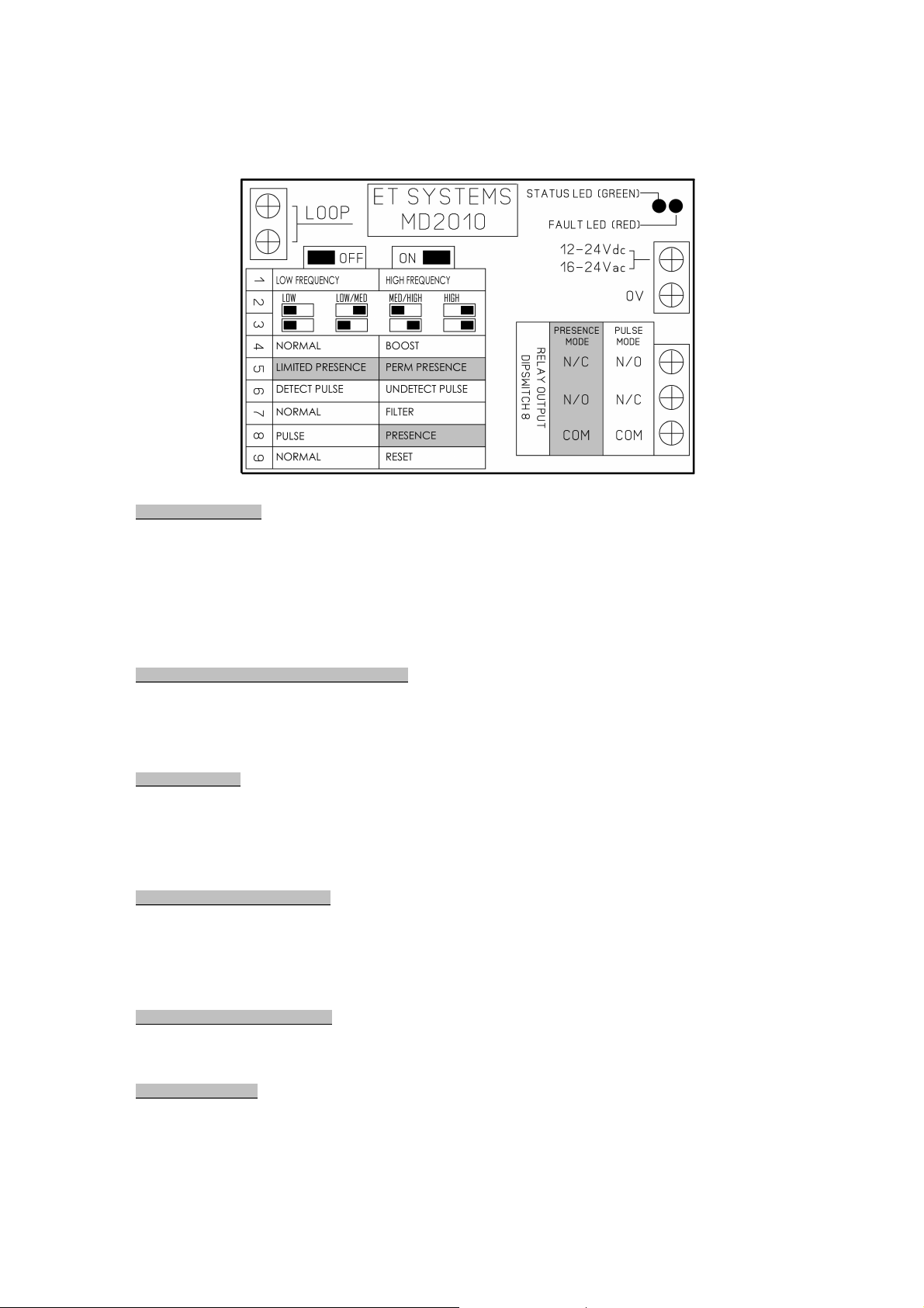
Outline of the Dip-switch setting options:-
Please note: The MD2010 must be reset (Dip 9 below) every time a setting change is made to the
dip-switches.
On initial power up the detector will also reset.
Dip-switch 1 – Freq. (Frequency):-
This setting is used in cases where two or more loop detectors and sensing loops have been installed. (The
sensing loops and detectors should be positioned at least 2m apart). Set one detector to HI frequency and the
other set to LO frequency to minimize the effects of crosstalk between the two systems.
OFF = Low frequency
ON = High frequency
Dip-switch 2 and 3 – Sensitivity:-
This setting determines the necessary change to the loop frequency to trigger the detector, as
metal passes across the sensing loop area.
2 OFF and 3 OFF = Low sensitivity 1% of loop frequency
2 ON and 3 OFF = Low to Medium sensitivity 0.5% of loop frequency
2 OFF and 3 ON = Medium to High sensitivity 0.1% of loop frequency
2 ON and 3 ON = High sensitivity 0.02% of loop frequency
Dip-switch 4 - Boost mode:-
If boost mode is ON the detector will immediately switch to high sensitivity once activated.
As soon as the vehicle is no longer being detected the sensitivity reverts back to what has been set on
dipswitch 2 and 3.
This mode is used when the height of the undercarriage of a vehicle increases as it passes over the sensing
loop.
OFF = No boost active
ON = Boost mode active
Dip-switch 5 – Permanent presence or limited presence mode:- (When presence mode selected.
See dip-switch 8)
Page 3
MD2010
METAL LOOP DETECTOR
This setting determines how long the relay remains active when a vehicle is stopped within the sensing loop
area.
ON = Permanent presence mode. The relay will remain active for as long as a vehicle is detected within the
sensing loop area. When the vehicle clears the sensing loop area, the relay will deactivate.
OFF = Limited presence mode. With limited presence mode on the detector will only activate the relay for 30
min.
If the vehicle has not moved out of the loop area after 25 min, the buzzer will sound to alert the user that the
relay will deactivate after another 5 min. Moving the vehicle across the sensing loop area again, after the relay
has deactivated, will re-activate the detector for 30 min.
Dip-switch 6 – Relay Response (when):- (Pulse mode only. See dip-switch 8)
This setting determines when the relay will activate.
OFF = PULSE ON DETECT. Relay activates immediately the vehicle is detected in the sensing loop area.
ON = PULSE ON UNDETECT. Relay activates immediately the vehicle leaves the sensing loop area.
Dip-switch 7 – Filter:-
This setting provides a 2 sec delay between when the metal object is detected and when the relays activate.
This option is used to prevent false activations when small or fast moving objects pass through the loop area.
This option can be used where an electric fence nearby is the cause of false activations.
If the object does not remain in the area for 2 sec the detector will not activate the relays.
Dip-switch 8 – Pulse mode or Presence mode:-
This setting determines how the relay responds to a vehicle standing still within the sensing loop
area.
ON = Presence mode. Relay will remain active, as per dip-switch 5 selection, for as
long as a vehicle is within the loop sensing area.
OFF = Pulse mode. Relay will activate for 1 sec only on entry or exit of sensing loop
area as set by dip-switch 6. To re-activate the vehicle must leave the sensing area
and re-enter.
Dip-switch 9 – Reset:-
Please note: The MD2010 must be reset every time a setting change is made to the Dip-switches!
To reset, switch Dip-switch 9 on for approximately 2 seconds and then off again. The detector then completes
the loop test routine.
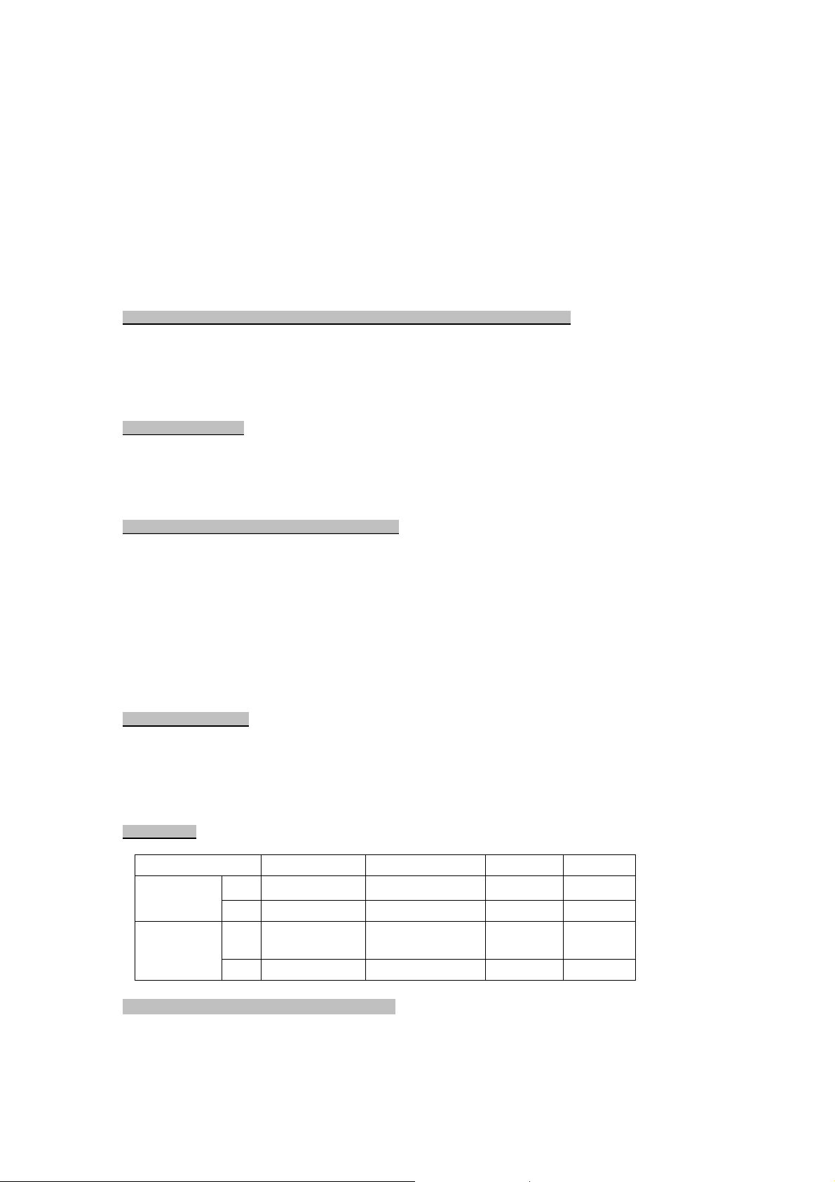
Relay status:
Relay Vehicle Present No vehicle present Loop faulty No Power
Presence
mode
Pulse mode
N/O Closed Open Closed Closed
N/C Open Closed Open Open
N/O
N/C Pulses open 1 sec.
Pulses closed 1
sec.
Open Open Open
Closed Closed Closed
On power up or reset the following will occur:-
Ensure the sensing loop area has been cleared of all loose pieces of metal, tools and vehicles
before powering up or resetting the detector!
Detector auto-tests the sensing loops:
Page 4
MD2010
Loo p w ire is o pen circuit. Use Dip-switch 9 after
Tone as long as vehicle
METAL LOOP DETECTOR
Faulty loop – Open loop or loop frequency below 20Khz:
Fault LED - 3 flashes, 3 sec pause, 3 flashes, 3 sec pause.........this continues until the faulty loop is
corrected and the detector is reset.
Buzzer - 3 beeps, 3 sec pause, 3 beeps, 3 sec pause.......repeats five times and then silences.
■
If the loop circuit is continuous (measure with continuity meter) then increase the loop
frequency by adding more turns of wire.
Faulty loop – Short circuited or loop frequency above 120Khz:
Fault LED – 6 flashes, 3 sec pause, 6 flashes, 3 sec pause - ..........this continues until the faulty loop is
corrected and the detector is reset.
Buzzer – 6 Beeps, 3 sec pause, 6 beeps, 3 sec pause..........repeats 5 times and then silences.
■
If there is no short circuit in the loop circuit then reduce the number wire turns around the
loop to reduce the loop frequency.
Good loop:
All three the Detect LED, Fault LED and the buzzer will beep/flash (count) between 2 and 11
times to indicate the loop frequency.
For example; 3 counts x 10Khz = Loop frequency of 30 – 40 KHz.
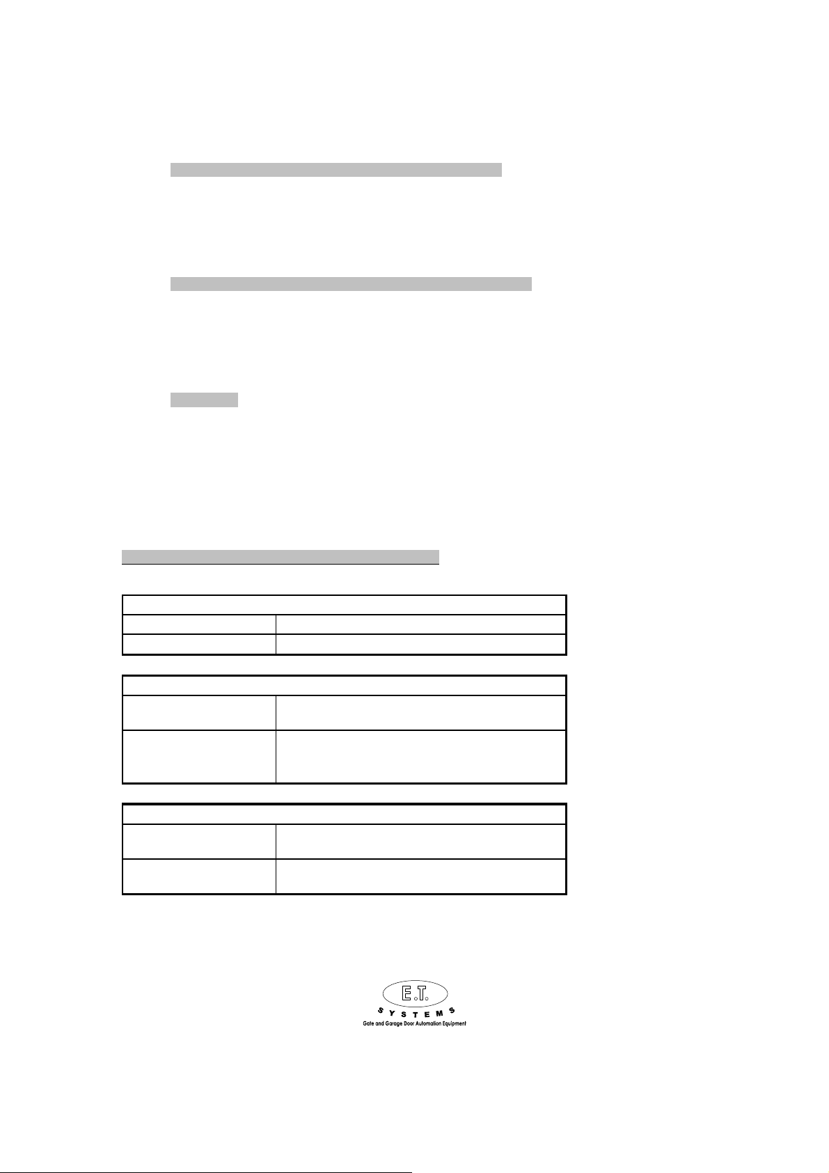
Buzzer and LED indications after initial power up/reset:
1 se c flashes 1 sec apart No ve hicle (me tal) de tected in loop are a.
On permanently Vehicle (met al) detected in loop area.
■
1 Count = 10Khz
Detect LED -
3 flashes 3 sec apart
6 flashes 3 sec apart
is in loo p area
Continuous tone w ith no
vehicle in the loop area
Fault LED -
any corection is m ade
Loo p w ire is short circuited. Use Dip-sw itch 9 after
any corection is m ade
Buzzer -
Buzzer sounds to confirm t he first ten dete ctions
Loo se w iring in loop or pow er term inals.
Use Dip-sw it ch 9 after any correction is made.
0860-109-238
 Loading...