

ET Solar ET-P660, ET-P636, ET-M660, ET-M672, ET-M572 Installation Manual
...
INSTALLATION
MANUAL(UL)
ET SOLAR SERIES MODULE
Contact Information Of Manufacturer:
You may contact our regional branches for questions and services:
Please consult your dealer or the manufacturer concerning the warranty of
your modules. If you have any further questions, your dealer and ET Solar will
gladly assist you.
Subject to technical modificaons without noce.2016 © ET Solar Group
Tel: 86 25 86898096 86898098
Fax: 86 25 86898097
E-mail: support@etsolar.com
www.etsolar.com
Tel: +1 925 4609 898
Fax: +1 925 4609 929
Email: sales @etsolar.us
19F, Block C, Wanda Plaza, Jianye District,
Nanjing 210019, China
4900 Hopyard Road, Suite 310, Pleasanton, CA 94588, USA
www.etsolar.com
Subject to technical modifications without notice. 2016 © ET Solar Group
www.etsolar.com
Subject to technical modifications without notice. 2016 © ET Solar Group
1
1
2
3
3.1
3.1.1
3.1.2
3.1.3
3.1.4
3.2
3.3
3.4
4
5
6
TABLE OF CONTENTS
ET Solar Group is a vertically integrated solar energy equipment manufacturer and
turnkey solutions provider. With local sales and marketing subsidiaries and offices
throughout Asia, Europe, and North America, we provide high quality photovoltaic
modules, world leading solar tracking systems and smart turnkey solutions to our
customers in more than 50 countries and areas. Our products have been delivering
strong operating performance in a large number of residential and utility scaled solar
PV projects around the world.
1. Company Introduction
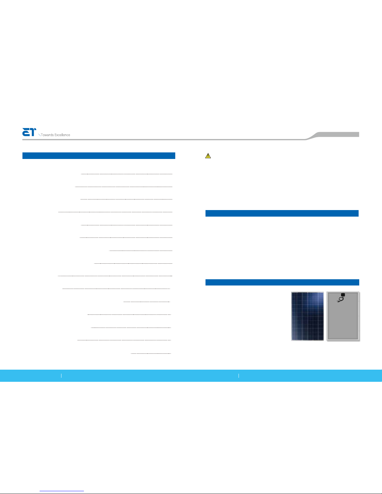
ET modules are made by layering
low-iron-tempered glass, an EVA sticky
membrane, high conversion-efficient solar
cells and a behind-the-membrane
multi-layer backsheet. These elements are
laminated into a plate by being heated in
a vacuum. After installing the aluminum
alloy frame and wiring compartment, a
module is born (see Fig. 1)
2. Structure of module
www.etsolar.com
Company Introduction
Structure of module
Installation of modules
Installation
Mounting with Bolts
Mounting with Clamps
Anti-salt module mounting procedure
Grounding of normal modules
Fire Safety
Junction box
Output Voltage, Current and Maximum Power
Characteristics of Modules
Operation and Maintenance
Disclaimer of liability
Appendix 1:Electrical ratings of ET Solar modules
1
1
2
2
3
3
4
7
9
10
13
14
15
15
16
The photovoltaic module produces electricity when exposed to the sun or other light
sources. For your safety and the safety of others, please read the entire Installation and
Assembly Instruction manual carefully prior to installation. Please carefully read the
following installation and safety instructions. Non-compliance with these instructions may
void the module warranty.
Fig.1 Front and back sides of
ET-P660260WW module
WARNING!
www.etsolar.com Subject to technical modifications without notice. 2016 © ET Solar Group www.etsolar.com Subject to technical modifications without notice. 2016 © ET Solar Group
2 3
The assembly is to be mounted over a fire resistant roof covering material when roof
mounting is intended for the modules, the fire resistance of roof covering or wall
should be rated for the application.
A torsion and corrosion-resistant anodized aluminum frame ensures dependable
performance, even under harsh weather conditions. Eight pre-drilled mounting holes,
located on the aluminum alloy frame, are provided for ease of installation. They are
designed to be used with metric M6×1(Torque 12 Lb-in) stainless steel screws.
The module must be attached and supported by at least four bolts through the
indicated mounting holes.
Most installations will use the four inner mounting holes on the module frame.
Depending on the local wind and snow loads, additional mounting points may be
required(e.g. if the combined wind and snow load is as high as 5400pa, please use
eight bolts).
If module clamps are used to secure the module, the torque on the clamp bolt
should be around 8–10 Nm.
A minimum of four module clamps should be used, two on each long frame side, in
the general clamping areas denoted by the wide arrows on the drawing.
Depending on the local wind and snow loads, additional module clamps may be
required(e.g. if the combined wind and snow load is as high as 5400pa, please use
eight clamps).
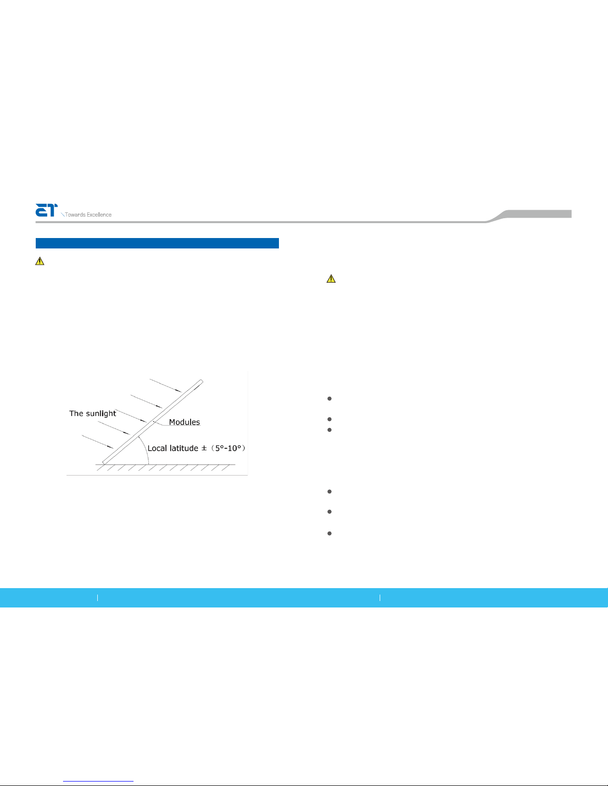
When installing the modules, the face of the units should be placed where they are
highly exposed to the sun. It is recommended that the modules usually face the
equator; thus, in the Northern Hemisphere the surface should be oriented towards the
south, and in the Southern Hemisphere, towards the north. Usually the angle between
modules and the ground should be local latitude ± (5°~10°) as shown in Fig.2.
The recommended standoff height is 5 in. (127mm).If other mounting means are
employed this may affect the UL Listing.
The specific angle depends on the sunlight condition, local climate and the actual
application requirements. The appropriate angle of elevation has a very important
relationship to the output power of the modules and the cost of the construction. The
surface of the modules should avoid shading and be kept clean from foreign
materials such as dirt.
3. Installation of modules
www.etsolar.com
3.1.1 Mounting with Bolts
3.1.2 Mounting with Clamps
WARNING!
3.1 Installation
Do not attempt to clean a module with a broken glass cover or a perforated
backsheet. Such a module can present a serious shock hazard.
WARNING!
The local shading of modules may cause serious hot-spots and damage the modules.
The modules are for use in applications where they do not serve as a member of the
building primary structural frame.
Fig.2 Assembly installation angle
 Loading...