

ET Solar ETM53680, ETM572155, ETM53685, ETM53675, ETM572160 Installation And Assembly Instructions
...Page 1

warranty.
Installation and Assembly Instructions
for Solar Modules
WARNING!
The photovoltaic module produces el ec tricity when expos ed to the sun or
other light sour ce s. For your saf ety an d t he s afet y of oth e rs, ple ase read
the entire Installation and Assembly Instruction manual carefully prior to
installation. Please carefully read the foll owing installation and safety
instructions. Non-compliance with these instructions may void the module
1. Company Introduction
ET Solar Group is a vertically integrated solar energy equipment manufacturer and
turnkey solutions provider. With local sales and marketing subsidiaries and offices
throughout Asia, Europe, and North America, we provide high quality photovoltaic
modules, world leading solar tracking systems and smart turnkey solutions to our
customers in more than 50 countries and areas. Our products have been delivering strong
operating performance in a large number of residential and utility scaled solar PV
projects around the world.
2. Structure of module
ET modules are made by layering low-iron-tempered glass, an EVA sticky membrane,
high conversion-efficient solar cells and a behind-the-membrane multi-layer backsheet.
These elements are laminated into a plate by being heated in a vacuum. After installing
the aluminum alloy frame and wiring compartment, a module is born (see Fig. 1)
.
1
Page 2
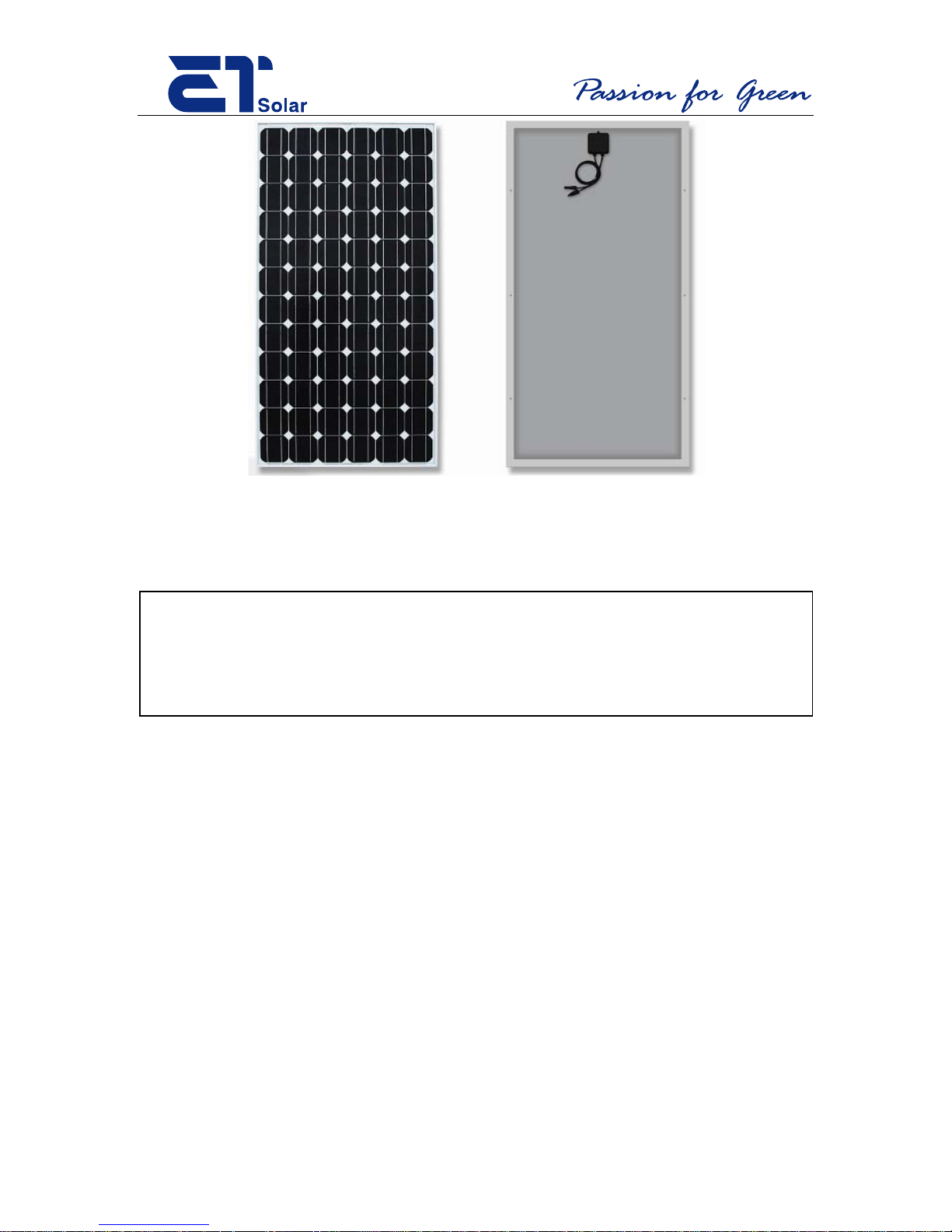
Fig.1: Front and back sides of ET-M572170 module
3. Installation of modules
WARNING!
Do not attempt to clean a module with a broken glass cover or a
perforated backsheet . Such a module can present a serious shock
hazard.
3.1 Installation
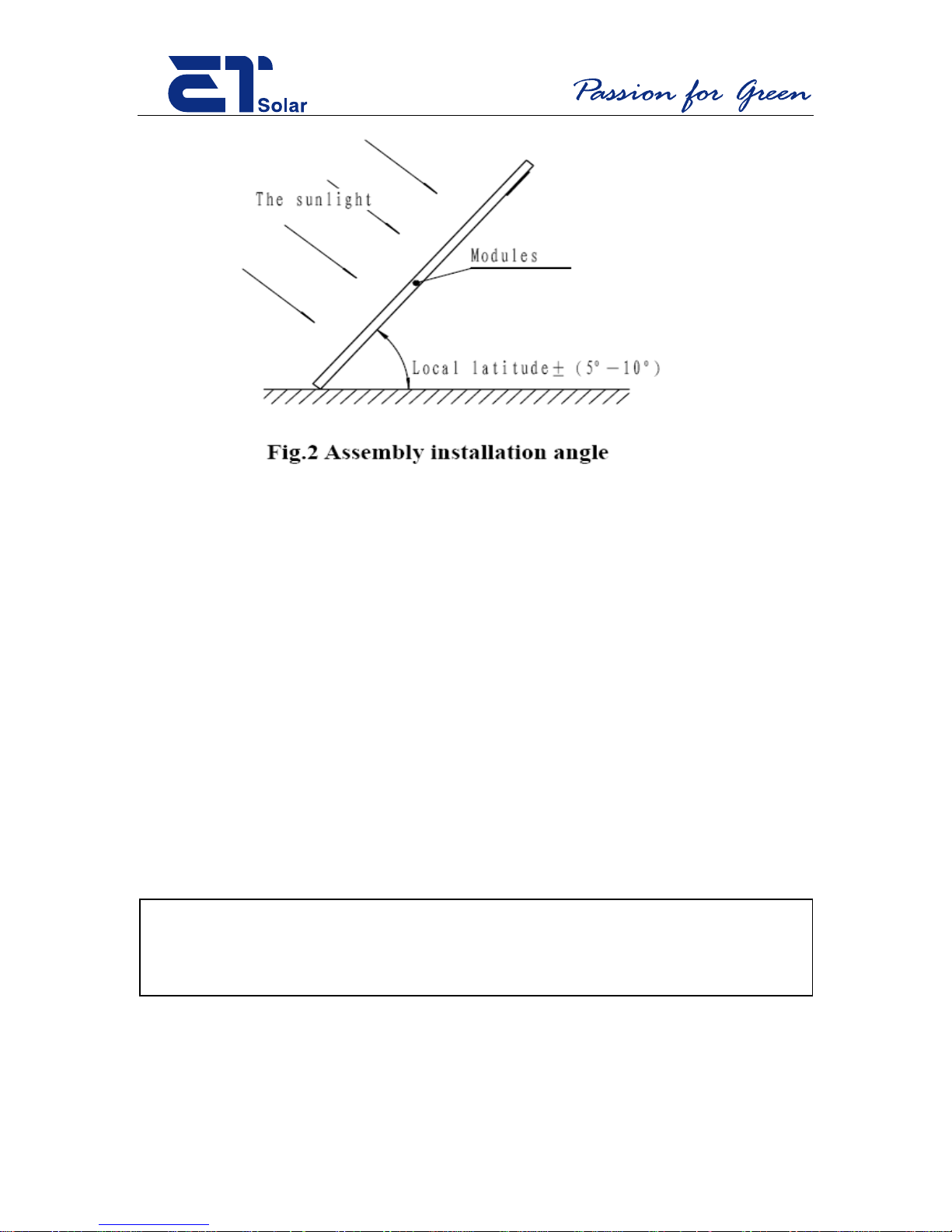
When installing the modules, the face of the units should be placed where they are highly
exposed to the sun. It is recommended that the modules usually face the equator; thus, i n
the Northern Hemisphere the surface should be oriented towards the south, and in the
Southern Hemisphere, towards the north. Usually the angle between modules and the
ground should be local latitude ± (5°~10°) as show in Fig.2.
2
Page 3
The recommended standoff height is 5 in. (127mm), if other mounting means are
employed this may affect the UL Listing.
The specific angle depends on the sunlight condition, local climate and the actual
application requirements. The appropriate angle of evaluation has a very important
relationship to the output power of the modules and the cost of the construction. The
surface of the modules should avoid shadows and be kept clean from foreign materials
such as dirt.
The assembly is to be mounted over a fire resistant roof covering material when roof
mounting is intended for the modules, the fire resistance of roof covering or wall should
be rated for the application.
WARNING!
The local shadowing of modules may cause se rious hot-spots and
damage the modules.
A torsion and corrosion-resistant anodized aluminum frame ensures dependable
performance, even under harsh weather conditions. Eight pre-drilled mounting holes,
3
Page 4
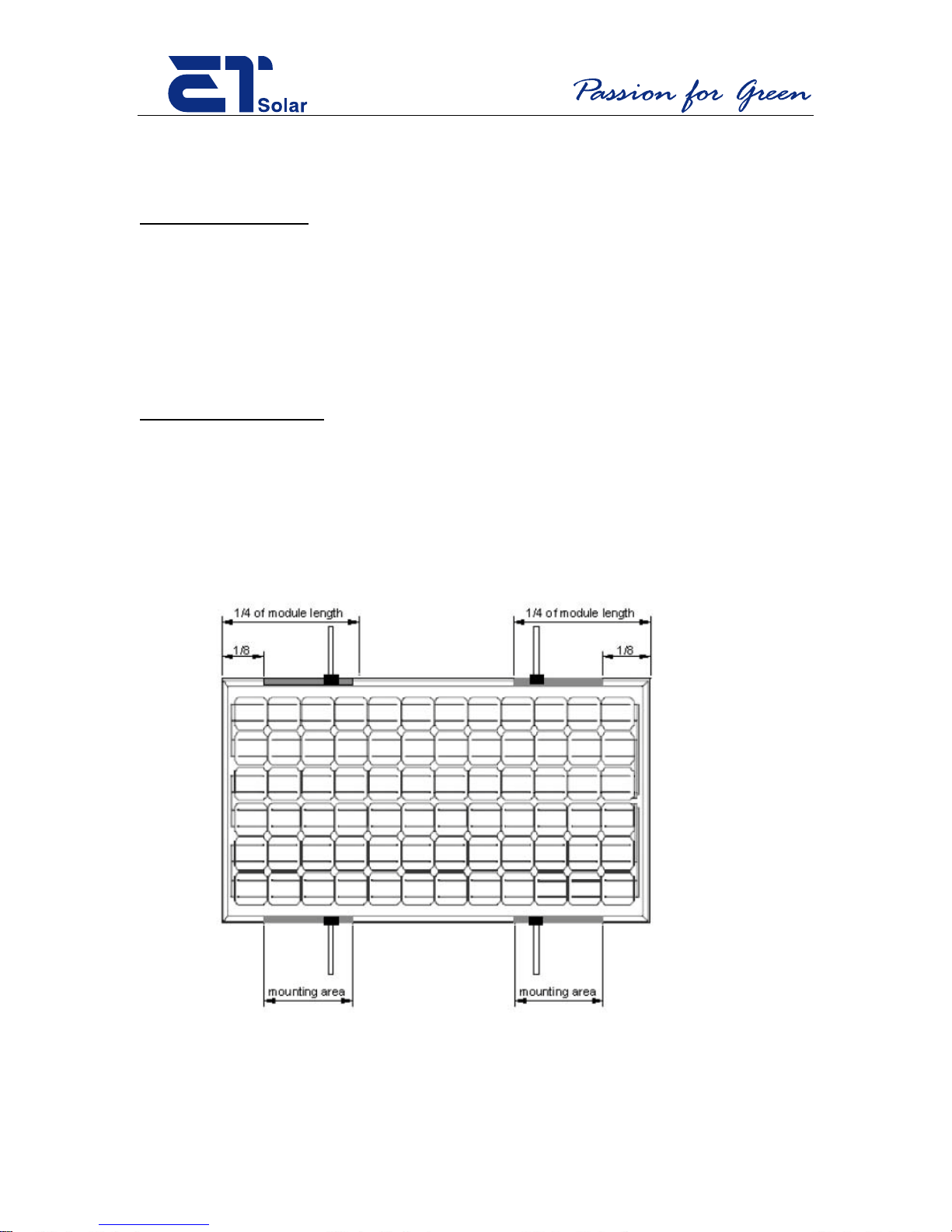
located on the aluminum alloy frame, are provided for ease of installation. They are
designed to be used with metric M6×1(Torque 12 Lb-in) stainless steel screws.
Mounting with Bolts
• The module must be attached and supported by at least four bolts through the
indicated mounting holes.
• Most installations will use the four inner mounting holes on the module frame.
• Depending on the local wind and snow loads, additional mounting points may be
required.
Mounting with Clamps
• If module clamps are used to secure the module, the torque on the clamp bolt
should be around 8–10 Nm.
• A minimum of four module clamps should be used, two on each long frame side,
in the general clamping areas denoted by the wide arrows on the drawing.
• Depending on the local wind and snow loads, additional module clamps may be
required.
4
Page 5
The Fire Rating of this modul e seri es is Class “C”.
WARNING!
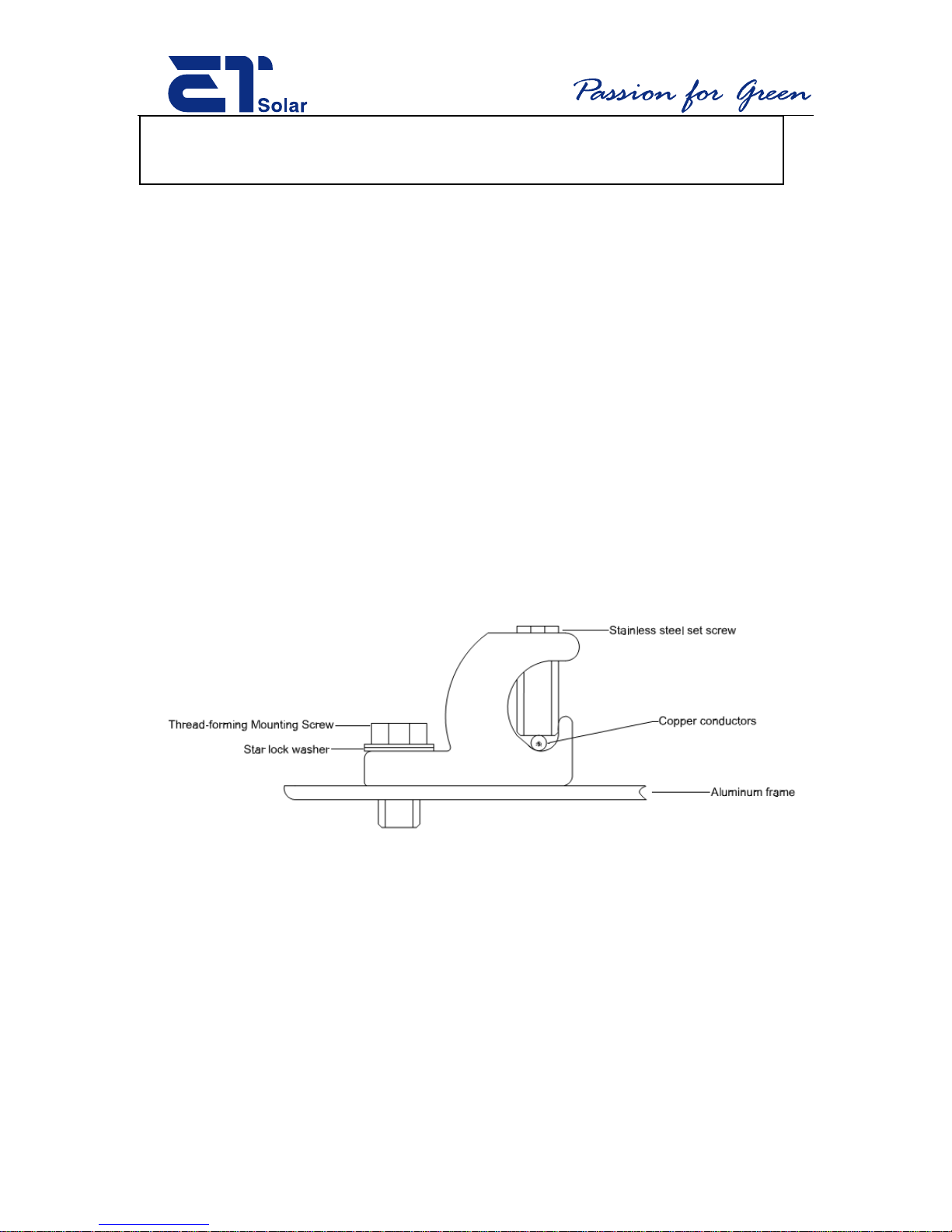
Grounding: All permanently mounted modules have to be provided with appropriate
grounding. The grounding lug should be suitable for outdoor use with aluminum. The
grounding method of the frame of arrays shall comply with the NEC, article 250 and also
meet UL 1703 standard. Lay-in-Lug ground part with 32 threads per inch (e.g., the layin-lug with UL file number E34440, part # GBL-4DB), with size #10-32 ½ inch stainless
steel thread cutting screw, and using a 20 lb*inch torque, should be mounted to one of the
4 mm diameter grounding holes marked as grounding hole on the frame. When the
module system is used, it should be connected to the ground reliably. The ground wire
should be a naked copper wire with surface coating only and with no insulation jacket.
The area of cross-section of wire should be sized in accordan ce with the prime current
carrying conductor. The area of cross-section of wire should meet the NEC, art icle 250.
Installation in Canada shall be in accordance with CSA C22.1, Safety Standard for
Electrical Installations, Canadian Electrical Code, Part 1 ( refer Figure 3)
Fig 3. PV module grounding with lay in lug (φ4mm grounding holes)
5
Page 6
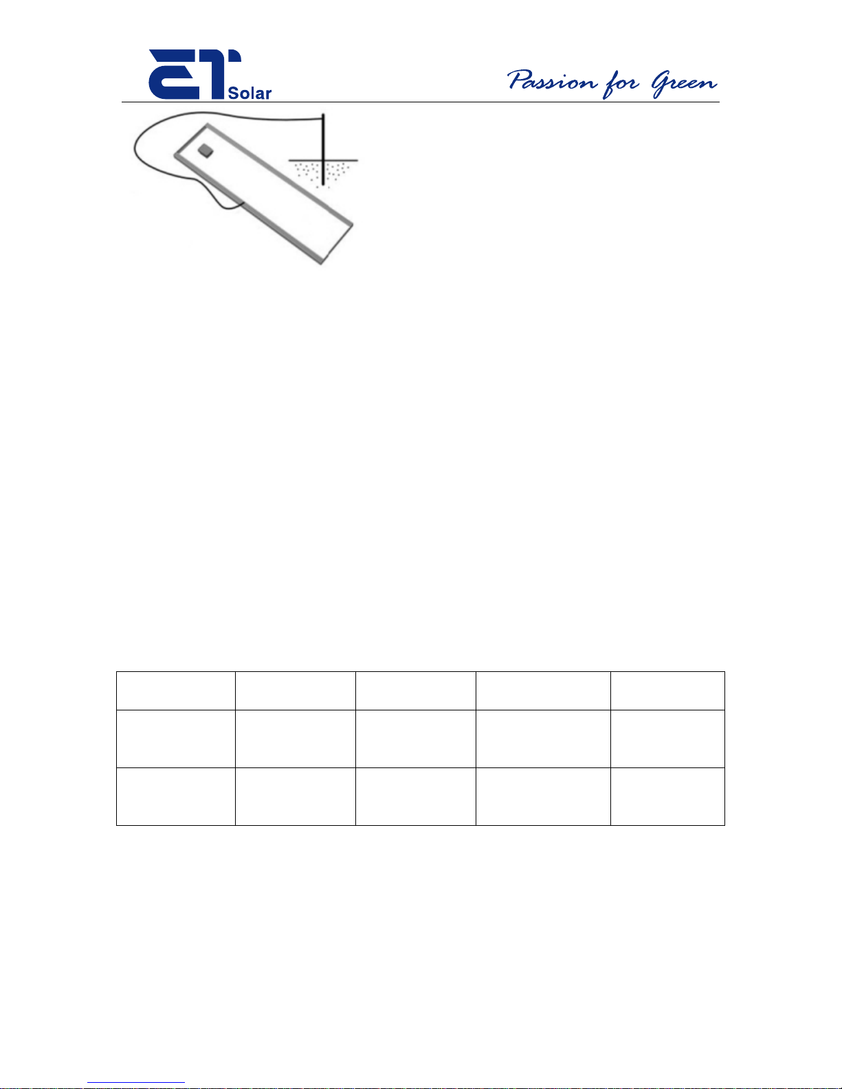
Module
Male connector
Female
connector
Manufacturer
Notes
ETP672series
ETP660 series
1394461-2
1394462-4
Tyco Electronics
12AWG wire
ETM572 series
Series
PV-KBT3
PV-KST3
Multi-Contact
12AWG wire
Fig 4. Module to grounding rod
3.2 Junction box
The junction box should be fixed on the top end of the module durin g assembly so as to
prevent the seepage of rain.
ET Solar provides a wiring type box. When the integrated J-box is adopted, no tool is
necessary for wiring. Just connect the modules in series according to “+” or “-”. You
can complete complex series and parallel connection easily and quickly using different
electric connectors provided by your supplier.
Connectors provided by different suppliers will not mutually match up. Different
connectors provided by one supplier will not match up either. Onl y one type of the same
connector from one supplier should be used to ensure the reliability of the electrical
connection.
ETP654 series
ETM53680
Amp GMBH
USA
There are other options i n addition to using a wiring type junction box only consisting of
two terminals marked with "+" and "-" to represent the positive and negative terminals of
the power supply. Some junction boxes include three or more terminals. Only those
terminals indicated with "+" and "-" should be connected to the load. The others are
designed for the bypass diodes to reduce the damage to modules caused by hot spots and
6
Page 7

suitable tools.
to ensure undisrupted electrical energy output from the array. The hex nut in the exit
position on the junction box is used to hold a rubber ring to seal the box.
When disconnecting the connectors of a photovoltaic module in a module array that is
exposed to sunlight, electric arcs may result. Such arcs may cause burns and fires.
Therefore, PV s ystem commissioning and maintenance must be performed by a qualified
electrician in accordance with the NEC. Before di sconnecting a module in a solar array,
disconnect the string of module from the DC Disconnect at the inverter side, and then
fully cover the module with an opaque material. Do not short the positive and the
negative connectors of a module exposed to sunlight.
WARNING!
Wiring must only be compl e t e d by a qualified engineer with
The specification of wire for the electri c coupler that ET Solar provided is 1 x 4.0mm2.
Equivalent wire should be used if the user prefers to use his own wire. When the
module’s rated current i s lower, 12AWG wire is recommended for use, and the strength
of the wire should be taken into consideration. ET Solar does not provide any output
wiring for module installation.
ET Solar modules are designed to use copper wire only. The working temperature of wire
and J-box is –40℃- 90℃. The wiring box interior is not intended for fiel d access, and no
serviceable parts are inside.
The installation in Canada shall be in accordance with CSA C22.1, Safety standard for
electrical installations, Canadian Electrical Code, Part 1.
3.3 Output Voltage, Current and Maximum Power
The open-circuit voltage (Voc), short-circuit current (Isc) and maximal power (Pmax) are
printed on the PET label on the backside of the module. The electri cal characte ristics are
within ±10 percent of the indicated values of Isc, Voc and Pmax under standard test
7
Page 8

process.
WARNING!
be irradiated directly under concentrate d li ght .
conditions (irradiance of 100 mW/cm2, AM1.5 spectrum, and a cell temperature of 25oC
(77oF)).
Under normal conditions, a photovoltaic module is likely to experience conditions that
produce more current and/or voltage than reported at standard test conditions.
Accordingly, the values of Isc and Voc marked on this module should be multiplied by a
factor of 1.25 when determining component voltage ratings, conductor capacities, fuse
sizes, and size of controls connected to the PV output. If modules are to be installed in
parallel (electrically), each module (or series string of modules so connected) shall be
provided with the maximum series fuse as specified.
WARNING!
In order to avoid electric shock and scalding, it is necessary to
cover the surface of the module with a suitable material to prevent
incidental light contacting the modules during the connection
The modules will generate electrical energy under sunlight and other light sources.
Refer to Section 690-8 of the National Electrical Code for an additional multiplying
factor of 125 percent (80 percent derating) which may be applicable.
4. Characteristics of Modules
The product is designed as a plai n plat e type that should not
The array consis ts of modules in s eries and parallel and has a similar electrical curve to
that of a single module. In order to output maximum electrical power to the load, try to
make the impedance of the load match the electric performance of the module or array. In
order to maintain the stability of the system, also pay attention to the changes in the
8
Page 9
Model
Open
c)
Rated
Maximu
m system
Rated
Short
Rated
power at
Maxi
ETM53670
21.45
16.9
600
4.14
4.45
70
7
ETM53675
21.73
17.4
600
4.31
4.72
75
ETM53680
21.88
17.64
600
4.54
4.98
80
ETM53685
21.94
18.05
600
4.71
5.29
85
ETM572155
43.30
35.20
600
4.40
4.98
155
12
ETM572160
43.90
35.26
600
4.49
5.07
160
ETM572165
44.12
35.68
600
4.60
5.19
165
15
ETM572170
44.16
36.13
600
4.71
5.3
170
ETM572175
44.25
36.24
600
4.83
5.50
175
ETM572180
44.60
36.30
600
4.95
5.61
180
ETM572185
44.60
36.30
600
5.09
5.80
185
ET-P654180
32.35
26.45
600
6.81
7.6
180
ET-P654185
32.3
26.45
600
6.99
7.7
185
ET-P654190
32.5
26.78
600
7.1
7.72
190
ET-P654195
32.75
27
600
7.22
7.98
195
ET-P654200
33.2
25.8
600
7.75
8.26
200
ET-P654205
32.8
27.3
600
7.5
8.1
205
ET-P654210
32.83
27.54
600
7.63
8.3
210
ET-P654215
33.2
27.54
600
7.81
8.5
215
ET-P654220
33.2
27.54
600
7.81
8.5
215
ET-P672230
43.56
34.2
600
6.75
7.32
230
ET-P672235
43.56
34.2
600
6.87
7.45
235
ET-P672240
43.85
34.95
600
6.88
7.63
240
ET-P672245
43.85
34.95
600
7.01
7.7
245
ET-P672250
43.88
35.2
600
7.12
7.81
250
ET-P672255
43.88
35.2
600
7.24
7.85
255
ET-P672260
43.49
34.8
600
7.47
8.18
260
ET-P672265
43.63
36.4
600
7.28
7.9
265
ET-P672270
43.63
36.4
600
7.43
7.9
270
electric curve of modules, especially under weak light. In more complex control circuits,
the controller supplier may have already adopted microprocessors for the tracking of
maximum power output. For the best impedance matching and the best tracking of
maximum power output, please refer to other relevant documents regarding these issues.
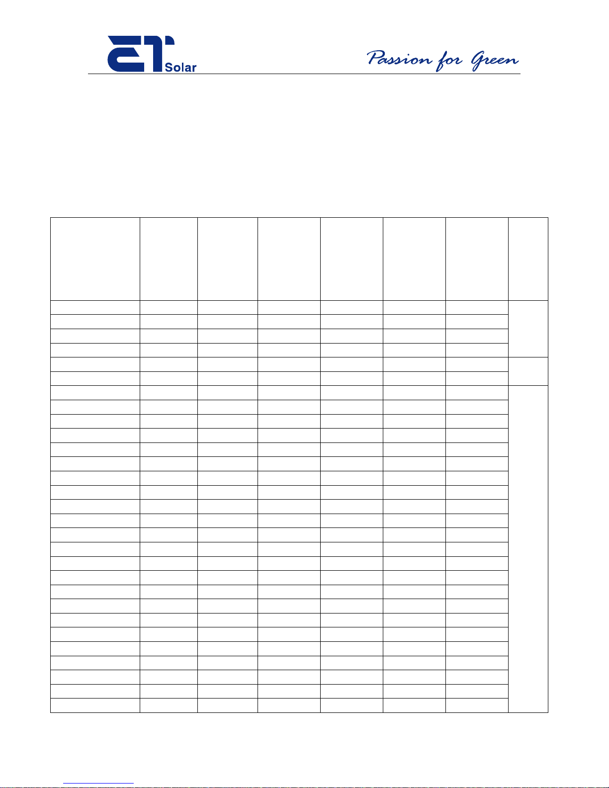
Electrical ratings of ET Solar modules are as follows. The detailed specs should refer to
module datasheet.
circuit
voltage
at
STC(Vd
Voltage
at
STC(Vdc
)
voltage(V
dc)
current at
STC(A
dc)
circuit
current at
STC(Adc)
maximum
STC(watt
s)
mum
series
fuse(
A)
9
Page 10

ET-P672275
43.78
36.72
600
7.49
7.96
275
ET-P672280
43.78
36.72
600
7.63
7.98
280
ET-P660200
36
28.75
600
7.7
7.71
200
15
ET-P660205
36
28.75
600
7.13
7.8
205
ET-P660210
36
28.75
600
7.3
7.99
210
ET-P660215
36
29
600
7.41
8.1
215
ET-P660220
36.3
29
600
7.58
8.1
220
ET-P660225
36.3
29
600
7.75
8.1
225
ET-P660230
36.5
29.4
600
7.82
8.3
230
ET-P660235
36.5
29.4
600
7.99
8.3
235
Usually the load of the modules is a group of batteries. To prevent the modules from
being charged by batteries under the circumstance of no sunlight, it is important to add a
shut-off diode in series. Also, please consider the voltage decrease of PN junction of
about 0.7V when connecting the shut-off diode. The modules can withstand for a
maximum positive or negative design loading of 45 lbs / ft2.
The environmental temperature may also affect the modules’ output power. If the
environmental temperature goes up, the short-circuit current will increase a little, while
open-circuit voltage wi ll decreas e, which will result in a decrease in the module’s output
power. Therefore, a lower environmental temperature is most appropriate for the module.
5. Operation and Maintenance
ET Solar module users should rinse the array seasonally or as needed in dry, dirty areas
to improve the performance of their solar electrical systems. Heavily soiled modules will
have a decrease in performance due to reduced light on the photovoltaic cells. Studies by
the PVUSA in Davis, CA estimate that during a dry year module soiling may affect
performance b y as much as 7% ann uall y with no cleani ng. Se asonal r ains often cl ean the
modules, however, during the long dry summer, it is helpful to rinse the modules as
needed.
ET solar modules may be rinsed with clean water to remove dirt. Normal pressure from a
standard residential hose and nozzle is recommended. Earl y morning and late afternoons
are favorable times to clean to avoid a sudden change in temperature. Care must be taken
since modules produce energy any time light is present. Modules are not to be touched or
walked on except by a licensed professional.
10
Page 11

Disclaimer of liability
Because the use of this manual and the conditions or methods of insta llation, operation, use
and maintenance of photo voltaic products are beyond ET Solar's control, ET Solar does not
accept responsibility and ex pr essly disclaims liabilit y for loss, damage, or expense arising
out of or in any way connected with such installation, operatio n, use or maintenance. No
responsibility is assu med by ET Solar for any infr ingement of patents or other r ights of third
parties, which may result from u s e of the PV product. No license is gr anted by implication or
otherwise under any patent or pat ent r ight s.
The information in this manual is based on ET Solar's knowledge and experience and is
believed to be reliable, but such information includin g pr oduc t specification (without
limitations) and suggesti ons does not constitute a w arr anty, expressed or implied. ET Solar
reserves the right to chan ge t he manual, the product, the specifications, or product
information sheets witho ut pr ior notice.
Contact information of manufacturer:
ET Solar Group Limited
24F, A2 World Trade Center Mansion,
67 Shanxi RD, Nanjing 210009, China
Tel: 86 25 86898096 86898098
Fax: 86 25 86898097
E-mail:
www.etsolar.com
You may contact our regio nal br anches for questions and services:
ET Solar Europe (Europe),
Munich City Towe r La nd sbe rge rst r. 110 -114, 9 Fl. D-80339
Munich, Ger m any
Tel: +49 89 5009405-0
Fax: +49 89 5009405-99
Email:Sales @etsolar.de
ET Solar USA (America & Canada )
4900 Hopyard Road, Suite 290, Pleasanton, CA 94588, USA
Tel: +1 925 4609 898
Fax: +1 925 4609 929
Email: sales @etsolar.us
11
Page 12

Please consult your dealer or the manufacturer concerning the warranty of your
modules. 2010 © ET Solar Group.
12
 Loading...