

Page 1
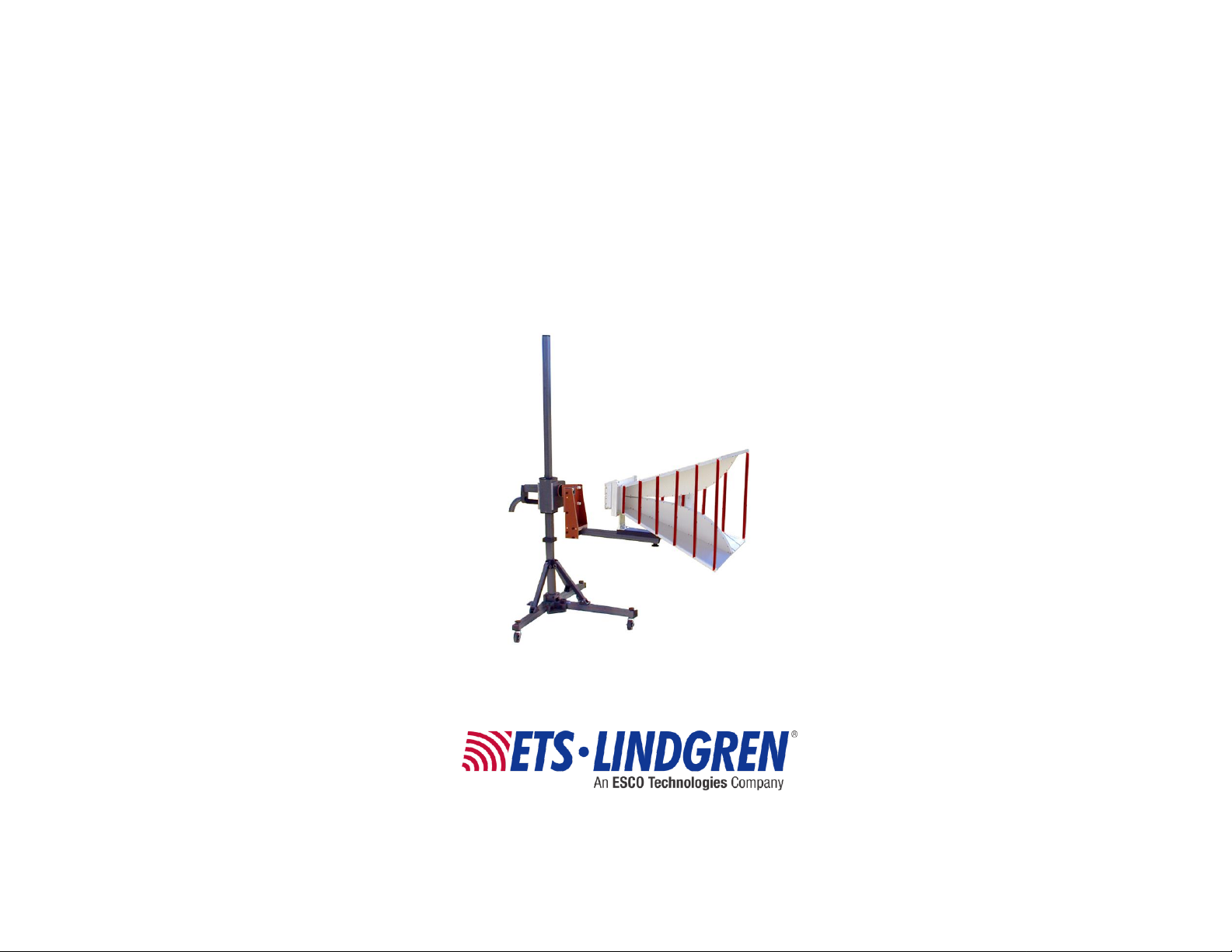
Model 7-TR
Tripod Positioner
User Manual
Model 3106B shown mounted onto 7-TR/POL-M
with optional 108507 centerline rotation boom
Page 2

ii
www.ets-lindgren.com
ETS-Lindgren Inc. reserves the right to make changes to any product described
Revision
Description
Date
A
Initial Release
October, 2000
B
C D Edits/updates
March, 2002
April, 2003
July, 2003
E
Added optional Pneumatic
Polarization Upgrade Kit information;
converted to half-size format
September, 2007
F
Added Boom Options; added
Model 3106B boom information;
rebrand
January, 2009
G
Updated part# of Pneumatic
Polarization Upgrade Kit to 112413
June, 2009
H
Updated Assembly Steps; updated
boom information; updated drawings
September, 2010
herein in order to improve function, design, or for any other reason. Nothing
contained herein shall constitute ETS-Lindgren Inc. assuming any liability
whatsoever arising out of the application or use of any product or circuit
described herein. ETS-Lindgren Inc. does not convey any license under its
patent rights or the rights of others.
© Copyright 2000–2014 by ETS-Lindgren Inc. All Rights Reserved. No part
of this document may be copied by any means without written permission
from ETS-Lindgren Inc.
Trademarks used in this document: The ETS-Lindgren logo is a registered
trademark and BiConiLog is a trademark of ETS-Lindgren Inc.
Revision Record | MANUAL, 7-TR | Part #399260, Rev. L
Page 3

www.ets-lindgren.com
iii
Revision
Description
Date
J
Updated boom options
June, 2013
K
Updated Replacement and Optional
Parts with 108507 boom information;
added Mounting a Model 3106
Series Antenna
July, 2013
L
Updated boom options for manual
and pneumatic models
July, 2014
Page 4

iv
www.ets-lindgren.com
This page intentionally left blank.
Page 5

www.ets-lindgren.com
v
Table of Contents
Notes, Cautions, and Warnings .............................................. vii
1.0 Introduction .......................................................................... 9
Boom Options ........................................................................................... 11
Polarization Options .................................................................................. 11
7-TR with No Polarization ................................................................. 12
7-TR with Pneumatic Polarization ..................................................... 13
7-TR with Manual Polarization .......................................................... 15
ETS-Lindgren Product Information Bulletin ............................................... 15
2.0 Maintenance ....................................................................... 17
O-Ring Lubricant ....................................................................................... 17
Boom Antenna Mount Knobs .................................................................... 18
Replacement and Optional Parts .............................................................. 18
Service Procedures .................................................................................. 21
3.0 Specifications ..................................................................... 23
Physical Specifications ............................................................................. 23
Electrical Specifications–Pneumatic Polarization Option ........................... 23
4.0 Assembling the 7-TR ......................................................... 25
Recommended Tools ................................................................................ 25
Assembly Components ............................................................................. 25
Assembly Steps ........................................................................................ 26
5.0 Mounting a Model 3106 Series Antenna .......................... 29
6.0 Pneumatic Polarization Upgrade Kit ................................ 35
Assembly Components ............................................................................. 35
Assembly Steps ........................................................................................ 36
7.0 Operation ............................................................................ 43
General Antenna Mounting Information ..................................................... 43
Adjusting the 7-TR Boom Height ............................................................... 44
Adjusting the 7-TR Leg Height .................................................................. 45
Using the Pneumatic Polarization Option .................................................. 46
Adjusting Air Polarization Speed ....................................................... 46
Using Pneumatic Polarization ........................................................... 47
Page 6

vi
www.ets-lindgren.com
Appendix A: Warranty ............................................................. 49
Page 7
www.ets-lindgren.com
vii
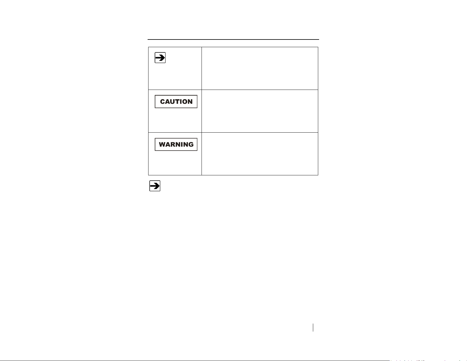
Notes, Cautions, and Warnings
Note: Denotes helpful information intended to
provide tips for better use of the product.
Caution: Denotes a hazard. Failure to follow
instructions could result in minor personal injury
and/or property damage. Included text gives proper
procedures.
Warning: Denotes a hazard. Failure to follow
instructions could result in SEVERE personal injury
and/or property damage. Included text gives proper
procedures.
See the ETS-Lindgren Product Information Bulletin for safety,
regulatory, and other product marking information.
Page 8

viii
www.ets-lindgren.com
This page intentionally left blank.
Page 9
www.ets-lindgren.com
Introduction
9
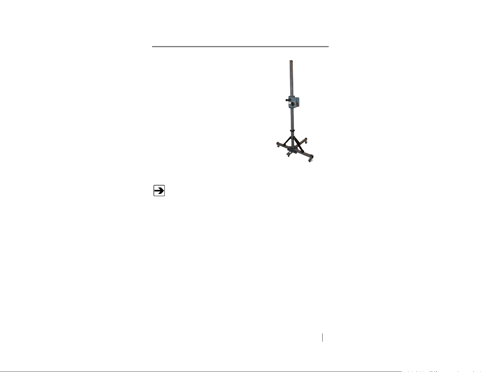
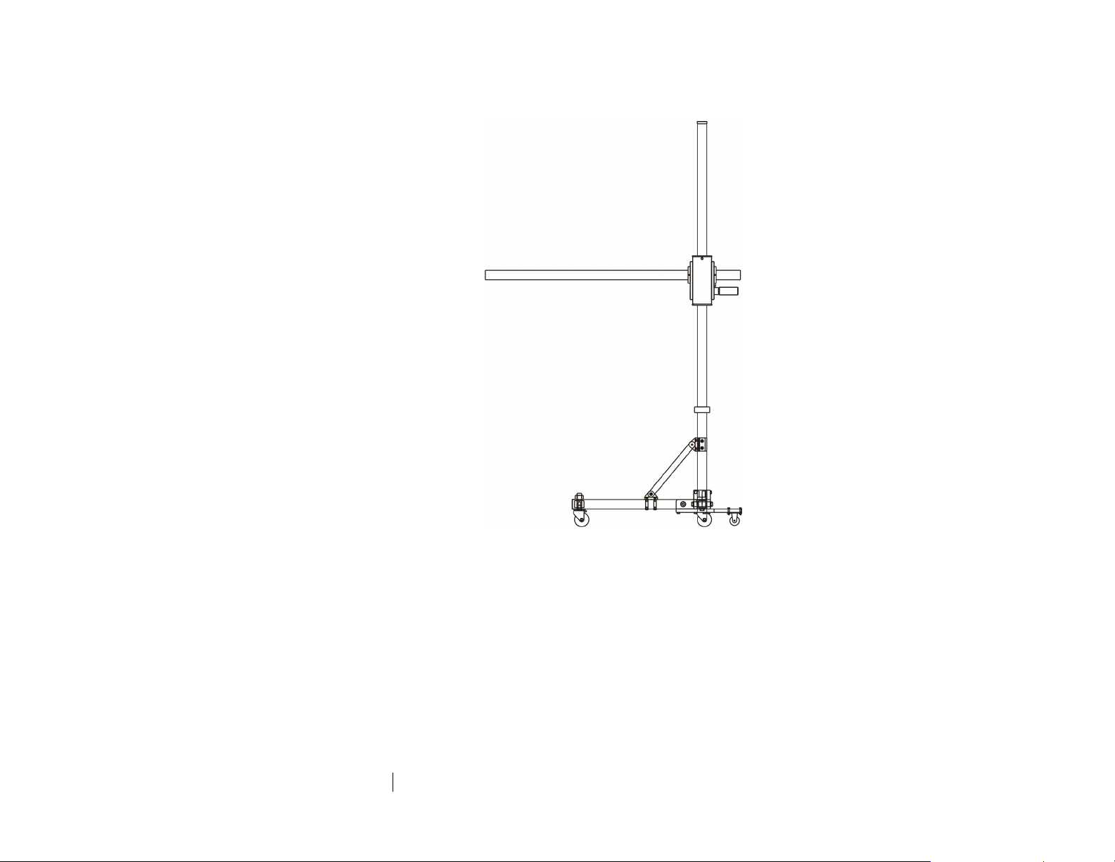
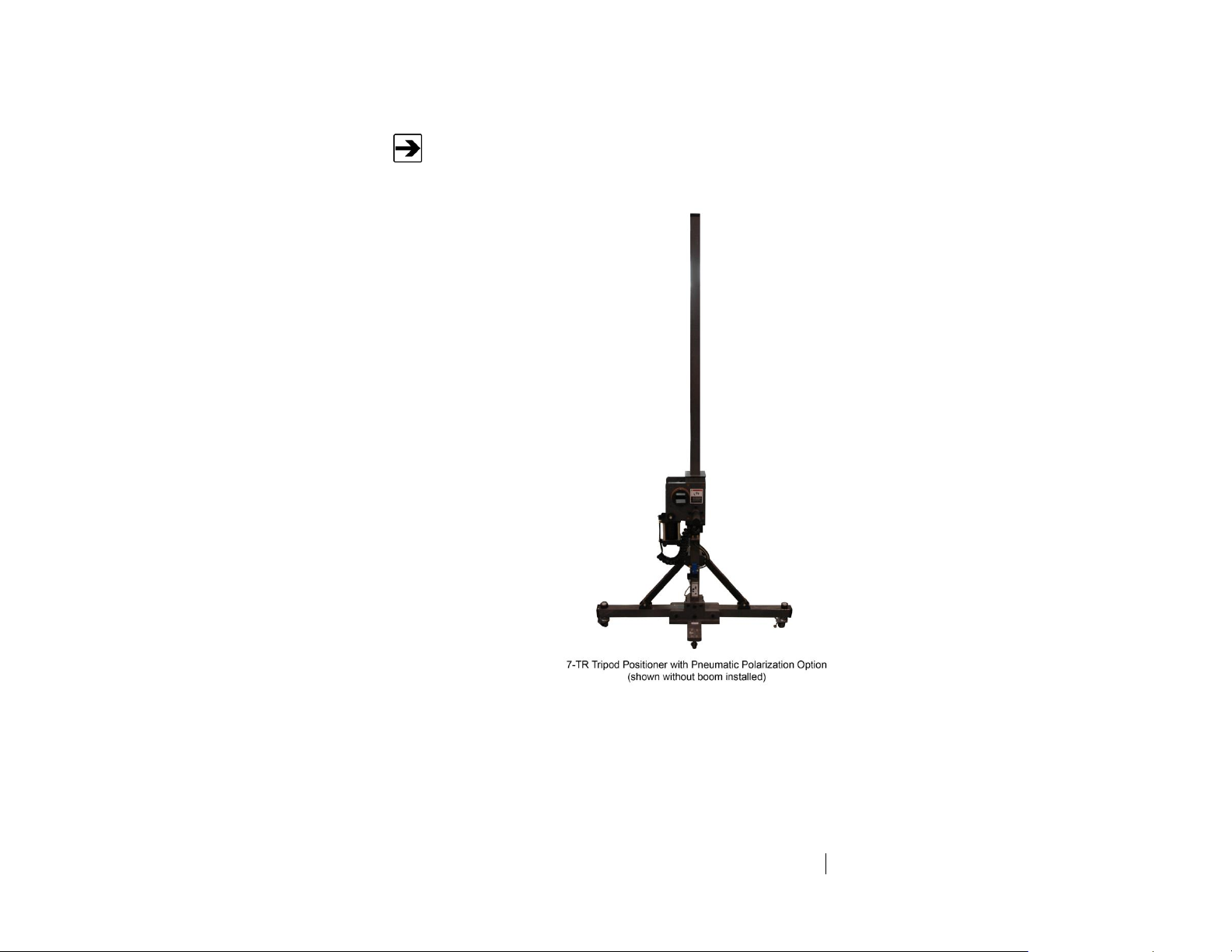
The ETS-Lindgren Model 7-TR Tripod
Positioner is designed for EMC testing,
providing increased stability for physically large,
ultra-broadband antennas, such as
ETS-Lindgren BiConiLog™ antennas. The 7-TR
boom height can be adjusted up and down from
one to two meters (3.3 to 6.6 ft), and can support
antennas up to 13.6 kg (30 lb). The fiberglass
and high-strength plastic construction makes it
non-conductive and non-magnetic.
7-TR/POL-M shown
without boom
Specify the type of boom required when ordering a 7-TR with manual
or pneumatic polarization; a boom is not included. For a list of
available booms, see Boom Options on page 11.
1.0 Introduction
Page 10
10
Introduction
www.ets-lindgren.com
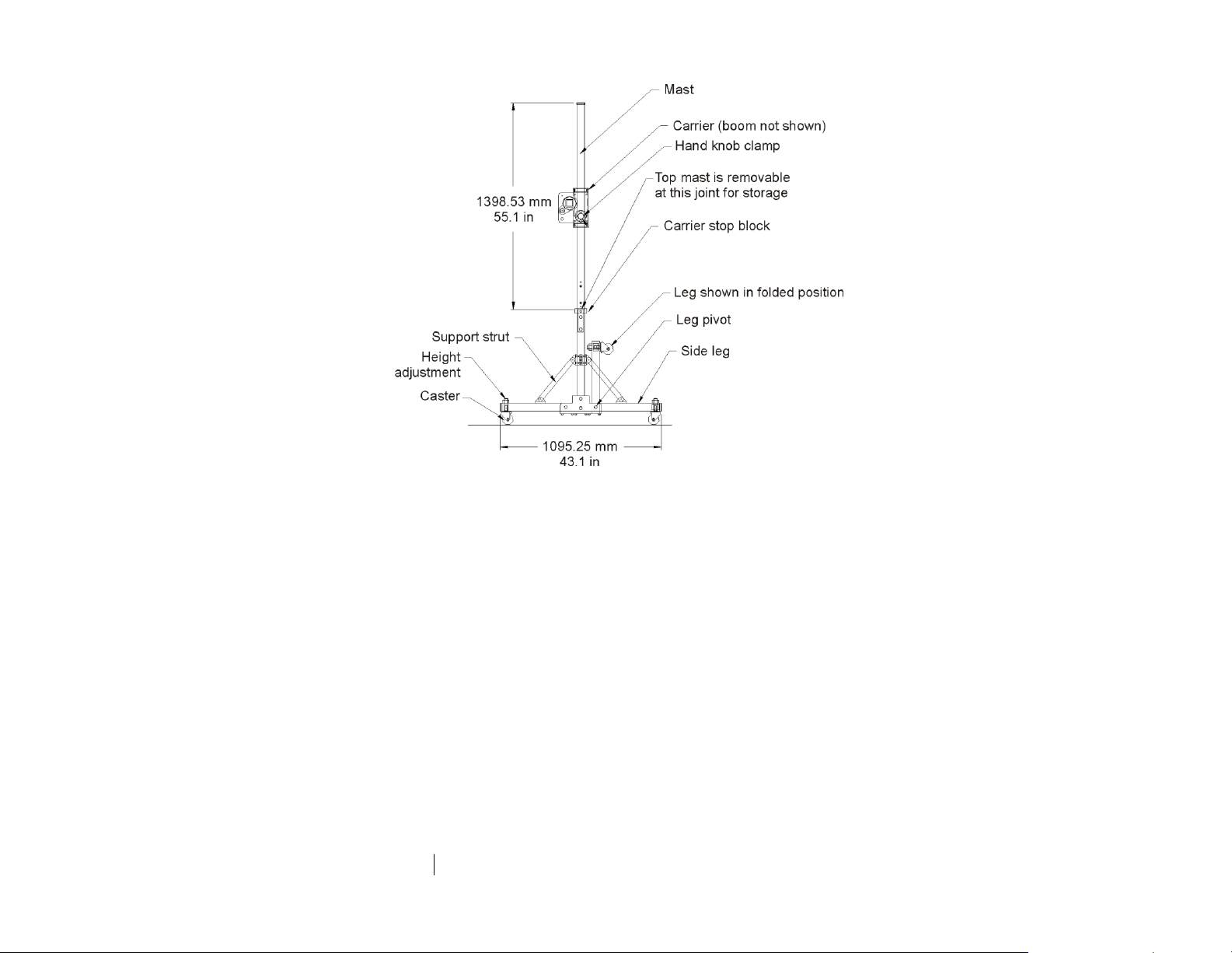
The boom is attached to the carrier and is locked into position with a
hand knob clamp. Standard mount knobs are included with the boom
to attach antennas securely to the boom.
Three horizontal legs extend from the base to support the mast and
maximize stability. Each leg has a caster with height adjustment for
leveling the mast on uneven surfaces. For convenient storage, the legs
can be folded upward and the top section of the mast removed.
Page 11

www.ets-lindgren.com
Introduction
11
Boom Type
Function
Straight (109042)
For general antenna mounting on a 7-TR.
Offset (108983)
For general antenna mounting on a 7-TR
with pneumatic or manual polarization. Can
also be used to mount stinger-type
antennas.
Stinger Only (118947)
For stinger mount antennas only.
Centerline Rotation (108507)
For Model 3106 Series antennas only; when
changing polarization, maintains centerline
rotation.
For mounting information, see Mounting a
Model 3106 Series Antenna on page 29.
Boom Options
A variety of booms for the 7-TR are available, depending on your antenna
model(s) and polarization requirements. For additional information see
Replacement and Optional Parts on page 18.
Polarization Options
The 7-TR is available with no polarization, with pneumatic polarization, or with
manual polarization; the following sections describe each option. Additionally, a
kit is available to upgrade an existing 7-TR from no polarization or manual
polarization to pneumatic polarization. See Pneumatic Polarization Upgrade Kit
on page 35 for more information.
Page 12
12
Introduction
www.ets-lindgren.com
The 7-TR with no
polarization option
includes a standard
boom assembly
(109042) for general
antenna mounting.
For information on
assembling a 7-TR,
see page 25. For
information on using
the 7-TR, see
page 43.
7-TR WITH NO POLARIZATION
Page 13
www.ets-lindgren.com
Introduction
13
Specify the type of boom required when ordering a 7-TR with manual
or pneumatic polarization; a boom is not included. For a list of
available booms, see Boom Options on page 11.
The 7-TR with pneumatic
polarization enables
remote rotation of an
antenna between
horizontal and vertical
positions while maintaining
a constant rotational axis
for the centerline of the
antenna. A coax cable
guide at one end minimizes
stress on cables during
use.
7-TR WITH PNEUMATIC POLARIZATION
Page 14

14
Introduction
www.ets-lindgren.com
The 1/4-in air hoses are UV stabilized with a 1/8-in National Pipe
Thread (NPT) fitting. The customer may supply a metric fitting for a
4-mm tube.
The pneumatic polarization option consists of the following components:
Air cylinder—Attaches to the carrier.
The air cylinder is made of non-conductive material, and is connected
by 6.3-mm (1/4-in) tubing to the Air Polarization Interface mounted to
the base of the 7-TR. The air cylinder will polarize antennas up to
13.6 kg (30 lb).
Twin air hose—Connects to Air Output.
Air hose—Connects to Air Input.
Air Polarization Interface—Mounts to the rear of the 7-TR mast.
The Air Polarization Interface requires 120 VAC (230 VAC is optional),
and approximately a 0.28 cubic meters/minute (1 CFM) air supply at
6 bars (90 PSI).
Pneumatic Interface—Mounts to the rear of the 7-TR mast, above the
Air Polarization Interface.
Fiber optic cable—Using a controller such as the Model 2090
Multi-Device Controller (or next generation ETS-Lindgren controller, if
applicable), enables horizontal and vertical boom rotation.
An air supply of 0.28 cubic meters per minute (1 CFM) at 6 bars (90 PSI) is
required for the pneumatic polarization option. It is important to have clean, dry
air; the use of a 40-micron filter in close proximity to the tripod installation is
recommended (not included).
For information on assembling a 7-TR, see page 25. For information on using the
7-TR, see page 43. For information on using the polarization option, see
page 46.
Page 15

www.ets-lindgren.com
Introduction
15
Specify the type of boom required when ordering a 7-TR with manual
or pneumatic polarization; a boom is not included. For a list of
available booms, see Boom Options on page 11.
7-TR WITH MANUAL POLARIZATION
For information on assembling a 7-TR, see page 25. For information on using the
7-TR, see page 43.
ETS-Lindgren Product Information Bulletin
See the ETS-Lindgren Product Information Bulletin included with your shipment
for the following:
Warranty information
Safety, regulatory, and other product marking information
Steps to receive your shipment
Steps to return a component for service
ETS-Lindgren calibration service
ETS-Lindgren contact information
Page 16

16
Introduction
www.ets-lindgren.com
This page intentionally left blank.
Page 17

www.ets-lindgren.com
Maintenance
17
Before performing any maintenance,
follow the safety information in the
ETS-Lindgren Product Information
Bulletin included with your shipment.
Maintenance of the Model 7-TR is limited
to external components such as cables
or connectors.
If you have any questions concerning
maintenance, contact ETS-Lindgren
Customer Service.
WARRANTY
2.0 Maintenance
O-Ring Lubricant
To prevent excessive wear of the O-rings, the air cylinder included with the
pneumatic polarization option uses an O-ring lubricant that can be purchased
from a seal or bearing store. To purchase O-ring lubricant from ETS-Lindgren,
see Replacement and Optional Parts on page 18 for the part number.
Page 18

18
Maintenance
www.ets-lindgren.com
ETS-Lindgren may substitute a similar part or new part number with the
same functionality for another part/part number. Contact ETS-Lindgren
for questions about part numbers and ordering parts.
Part Description
Part Number
7-TR Tripod Options
1. 7-TR Tripod, No Polarization
7-TR
2. 7-TR Tripod, Pneumatic Polarization
7-TR/POL
3. 7-TR Tripod, Manual Polarization
7-TR/POL-M
Pneumatic Polarization Upgrade Kit
112413
Boom Antenna Mount Knob, 0.875-14 THD (7/8-14)
104136
Boom Antenna Mount Knob, 0.250-20 THD (1/4-20)
104169
O-Ring Lubricant
890437
Boom Antenna Mount Knobs
Each boom option for the Model 7-TR Tripod Positioner includes two boom
antenna mount knobs. The mount knobs can be threaded through the perforated
boom and into the antenna mount to secure an antenna into place. For additional
mount knobs contact ETS-Lindgren Customer Service.
Replacement and Optional Parts
Page 19

www.ets-lindgren.com
Maintenance
19
Part Description
Part Number
Boom Assembly Options
1. Boom Assembly, Antenna Mounting, Straight—Standard
for general antenna mounting on 7-TR
109042
2. Boom Assembly, Antenna Mounting, Offset—Standard
for general antenna mounting on 7-TR/POL and
7-TR/POL-M; can also be used to mount stinger-type
antennas
108983
3. Boom,Stinger Only— For stinger-mount antennas only.
118947
Stinger boom, 118947
Straight boom, 109402
Offset boom, 108983
Page 20

20
Maintenance
www.ets-lindgren.com
Part Description
Part Number
4. Boom Assembly, Antenna Mounting, 3106—For
mounting Model 3106 antennas only
108507
For mounting information, see Mounting a Model 3106 Series Antenna on
page 29.
3106 Series boom,
108507
Model 3106B shown mounted onto 7-TR/POL-M
with optional 108507 centerline rotation boom
Page 21

www.ets-lindgren.com
Maintenance
21
Service Procedures
For the steps to return a system or system component to ETS-Lindgren for
service, see the Product Information Bulletin included with your shipment.
Page 22

22
Maintenance
www.ets-lindgren.com
This page intentionally left blank.
Page 23

www.ets-lindgren.com
Specifications
23
Height:
217.9 cm (85.8 in)
Width:
109.5 cm (43.1 in)
Depth:
154.9 cm (61 in)
Weight (with pneumatic
polarization option):
26 kg (58 lbs)
Load Capacity:
13.6 kg (30 lbs)
110 V
220 V
Power Supply:
160 mA
80 mA
Frequency:
60 Hz
50 Hz
Power Input:
160 mA
80 mA
Interface Device:
500 mA
12 VDC
300 mA
12 VDC
I/O Ports:
ST Fiber Optic Input
ST Fiber Optic Input
3.0 Specifications
Physical Specifications
Electrical Specifications–Pneumatic Polarization Option
Page 24

24
Specifications
www.ets-lindgren.com
This page intentionally left blank.
Page 25

www.ets-lindgren.com
Assembling the 7-TR
25
Before assembling or connecting any
components, follow the safety information in
the ETS-Lindgren Product Information Bulletin
included with your shipment.
4.0 Assembling the 7-TR
Recommended Tools
15- or 20-cm (6- or 8-in) adjustable open-end wrench
#2 Phillips screwdriver
#3 Phillips screwdriver
Hex key
Assembly Components
Mast assembly with carrier and folded legs
Top mast section
Boom antenna mount knob, 0.250-20 (1/4-20)
Boom antenna mount knob, 0.875-14 (7/8-14)
Boom assembly
Mounting hardware
Page 26

26
Assembling the 7-TR
www.ets-lindgren.com
Assembly Steps
1. Remove the three lock pins that hold the three legs against the mast.
You will re-use the lock pins in the next step.
2. Lower the three legs and secure the support struts to the mast with the
lock pins.
3. Place the base of the Model 7-TR Tripod Positioner on the floor and
install the top mast section onto the bottom mast.
Page 27

www.ets-lindgren.com
Assembling the 7-TR
27
See Operation on page 42 for information on adjusting boom height,
leg height, and mounting an antenna.
4. Install the boom:
Orient the boom so the mounting holes are to the front of the
7-TR. If the boom has a cable guide (not shown), orient the
cable guide to the rear of the 7-TR.
If the boom has a cable guide, remove the cable guide from the
end of the boom.
Insert the end of the boom through the front and rear
carrier collars, leaving five inches of boom on the hand knob
clamp side of the carrier.
Secure the boom with the 1/4-20 set screws located in the
carrier collars.
5. If the boom has a cable guide, reinstall the cable guide.
Page 28

28
Assembling the 7-TR
www.ets-lindgren.com
This page intentionally left blank.
Page 29

www.ets-lindgren.com
Mounting a Model 3106 Series Antenna
29
Before connecting any components or
operating the Model 7-TR, follow the safety
information in the ETS-Lindgren
Product Information Bulletin included with
your shipment.
You will need assistance from two team members
to mount a Model 3106 Series antenna to the 7-TR.
You must install the 108507 boom onto the 7-TR before performing
these steps. For clarity, the following illustrations do not show the
7-TR.
ETS-Lindgren may substitute a similar part with the same functionality
for another part (for example, a wingnut for a hex nut).
1. Remove the two
104136 boom knobs
from the underside of
the 108507 boom.
You will re-use the
knobs in step 7.
5.0 Mounting a Model 3106 Series Antenna
The following steps to mount a Model 3106B Double-Ridged Waveguide Horn
Antenna onto a 108507 boom apply to all Model 3106 Series antennas.
Page 30

30
Mounting a Model 3106 Series Antenna
www.ets-lindgren.com
2. Lift the mount adapter
up and away from the
boom.
3. Remove the wingnut to
free the 1/4–20 screw
from the mount adapter.
You will re-use the screw
in step 6.
4. Remove the nuts to
free the two screws
from the vertical plate
on the mount adapter.
You will re-use the
screws in step 6.
Page 31

www.ets-lindgren.com
Mounting a Model 3106 Series Antenna
31
Retain these two screws for future use; if you remove the
Model 3106B from the 7-TR, you will need to replace these screws to
provide support for the inner ridge of the antenna.
5. On the side of the
Model 3106B with the
antenna connector,
remove the two
screws from the mount
plate.
Page 32

32
Mounting a Model 3106 Series Antenna
www.ets-lindgren.com
6. Attach mount adapter to the Model 3106B:
Using the two screws removed in step 4, insert the screws
through the lip on the vertical part of the mount adapter and
into the two holes on the antenna. Tighten to secure.
Using the screw removed in step 3, insert the screw through
the horizontal part of the mount adapter and into the mount
block on the antenna. Tighten to secure.
Page 33

www.ets-lindgren.com
Mounting a Model 3106 Series Antenna
33
7. Attach the mounted assembly to the boom: Use the two
104136 knobs removed in step 1 to attach the antenna and mount
adapter assembly to the boom. Tighten to secure.
Page 34

34
Mounting a Model 3106 Series Antenna
www.ets-lindgren.com
This page intentionally left blank.
Page 35

www.ets-lindgren.com
Pneumatic Polarization Upgrade Kit
35
Before assembling or connecting any
components, follow the safety information in
the ETS-Lindgren Product Information Bulletin
included with your shipment.
6.0 Pneumatic Polarization Upgrade Kit
Assembly Components
The Pneumatic Polarization Upgrade Kit for the Model 7-TR Tripod Positioner
upgrades a 7-TR with no polarization or manual polarization to pneumatic
polarization. The kit includes these major components:
Carrier
Air cylinder
Air Polarization Interface
Pneumatic Interface
Power supply
Air hoses
Mounting hardware
Page 36

36
Pneumatic Polarization Upgrade Kit
www.ets-lindgren.com
Assembly Steps
1. Remove the boom from the carrier on the 7-TR:
Remove the 1/4-20 set screws located in the carrier collars that
secure the boom.
If the boom has a cable guide, remove the cable guide from the
end of the boom.
Completely remove the boom from the carrier by withdrawing it
towards the front of the 7-TR.
Page 37

www.ets-lindgren.com
Pneumatic Polarization Upgrade Kit
37
2. Remove the carrier from the mast on the 7-TR:
Remove protective cap from top of mast.
Unscrew the hand knob clamp.
Lift to completely remove the carrier from mast.
3. Install the new carrier:
Insert the new carrier onto the top of the mast.
Slide the carrier down the mast to the desired height.
Tighten the hand knob clamp to secure the carrier into place.
Page 38

38
Pneumatic Polarization Upgrade Kit
www.ets-lindgren.com
4. Install pneumatic polarization components:
The mast includes mounting holes for the pneumatic polarization
components. Place components into position as indicated in the
previous illustration.
Secure components into place with appropriate mounting
hardware.
Page 39

www.ets-lindgren.com
Pneumatic Polarization Upgrade Kit
39
5. Connect coiled tubing from air cylinder to compression connectors on
right-angle bracket.
6. Connect twin air hose:
Plug ends of the twin air hose into the connectors on the side of
the Pneumatic Interface.
Plug the other ends of the twin air hose into the compression
connectors on the right-angle bracket.
Tighten both sides of the compression connectors.
Page 40

40
Pneumatic Polarization Upgrade Kit
www.ets-lindgren.com
7. Plug one end of the single air hose into the Solenoid Connection on
the Air Polarization Interface.
8. Plug the other end of the single air hose into the connector on the
bottom of the Pneumatic Interface.
Page 41

www.ets-lindgren.com
Pneumatic Polarization Upgrade Kit
41
9. Connect tubing (provided) from Pneumatic Interface to the air supply.
10. Plug one end of the fiber optic cable into the Fiber Optic Input on the
Air Polarization Interface.
11. Plug the other end of the fiber optic cable into the Model 2090
Multi-Device Controller (or next generation ETS-Lindgren controller, if
applicable), or other controller.
12. Install the boom:
Orient the boom so the mounting holes are to the front of the
7-TR. If the boom has a cable guide, orient the cable guide to the
rear of the 7-TR.
If the boom has a cable guide, remove the cable guide from the
end of the boom.
Insert the end of the boom through the front and rear
carrier collars, leaving five inches of boom on the hand knob
clamp side of the carrier.
Secure the boom with the 1/4-20 set screws located in the
carrier collars.
13. If the boom has a cable guide, reinstall the cable guide.
14. Replace the protective cap removed in step 2 onto the top of the mast.
Page 42

42
Pneumatic Polarization Upgrade Kit
www.ets-lindgren.com
Prior to mounting an antenna or using the 7-TR, see Operation on
page 42.
15. Connect power:
Plug the power cable into the Power IN on the Air Polarization
Interface.
Connect the power supply to the power source.
Page 43

www.ets-lindgren.com
Operation
43
Before connecting any components or
operating the Model 7-TR, follow the safety
information in the ETS-Lindgren
Product Information Bulletin included with
your shipment.
If using a Model 7-TR with pneumatic polarization, test the air
polarization speed prior to mounting an antenna. For the steps to
adjust air polarization speed, see page 46.
To reduce stress and deflection, attach the antenna as close to the
carrier as possible.
7.0 Operation
General Antenna Mounting Information
ETS-Lindgren antennas can be attached to the boom on the Model 7-TR Tripod
Positioner using either the 104136 or 104169 boom antenna mount knob. The
boom includes mounting holes for attaching antennas.
Page 44

44
Operation
www.ets-lindgren.com
Adjusting the 7-TR Boom Height
1. Grasp the hand knob clamp with one hand while supporting the boom
with the other.
2. Loosen the hand knob clamp, and then lower or raise the carrier to the
desired height.
3. Tighten the hand knob clamp to secure the carrier and boom into
place.
Page 45

www.ets-lindgren.com
Operation
45
Adjusting the 7-TR Leg Height
The casters include a threaded stem that can be rotated to raise or lower the
extension leg. To adjust the height:
1. Loosen the 1-in plastic hexagonal nut on the top of the stem.
2. Rotate the base of the stem just below the leg.
3. Repeat for the remaining leg.
Page 46

46
Operation
www.ets-lindgren.com
Damage to the antenna may occur if the air
polarization speed is set too high. Adjust the
flow control valves to prevent damage.
Using the Pneumatic Polarization Option
ADJUSTING AIR POLARIZATION SPEED
Flow control valves attached to the air cylinder allow variable speed on
polarization cycling. Use a small screwdriver to adjust the air flow through the
two 90-degree fittings.
Page 47

www.ets-lindgren.com
Operation
47
1. Turn on the air supply and power.
2. Press the Manual Polarization button on
the Air Polarization Interface.
3. Adjust polarization speed as necessary.
USING PNEUMATIC POLARIZATION
Page 48

48
Operation
www.ets-lindgren.com
This page intentionally left blank.
Page 49

www.ets-lindgren.com
Warranty
49
See the Product Information Bulletin included with your shipment for
the complete ETS-Lindgren warranty for your Model 7-TR.
Product Warranted
Duration of Warranty Period
Model 7-TR Tripod Positioner
2 Years
Appendix A: Warranty
DURATION OF WARRANTIES FOR MODEL 7-TR
All product warranties, except the warranty of title, and all remedies for warranty
failures are limited to two years.
 Loading...