

Page 1
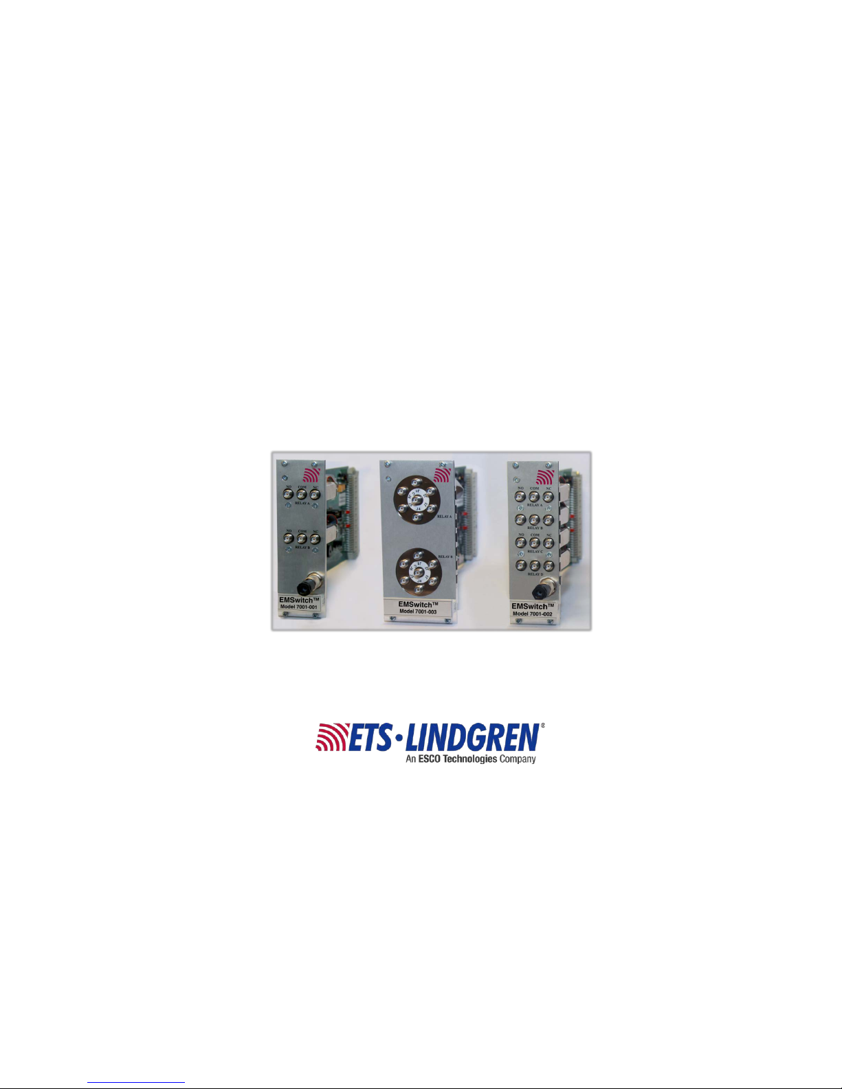
EMSwitch™
RF Switch Plug-In Card
User Manual
Model 7001-001 Model 7001-003 Model 7001-002
(not all models shown)
Page 2

ii ets-lindgren.com
ETS-Lindgren Inc. reserves the right to make changes to any product described herein in
order to improve function, design, or for any other reason. Nothing contained herein shall
constitute ETS-Lindgren Inc. assuming any liability whatsoever arising out of the application
or use of any product or circuit described herein. ETS-Lindgren Inc. does not convey any
license under its patent rights or the rights of others.
© Copyright 2014–2016 by ETS-Lindgren Inc. All Rights Reserved. No part of this
document may be copied by any means without written permission from
ETS-Lindgren Inc.
Trademarks used in this document: The ETS-Lindgren logo is a registered trademark, and
EMCenter, EMSwitch, TILE!, and EMQuest are trademarks of ETS-Lindgren Inc.
Revision Record
MANUAL, EMSWITCH | Par t # 399343, Rev. E
Revision Description Date
A Initial Release June, 2014
B Updated EMCenter models June, 2014
C Added Model 7001-005; updated
EMSwitch Remote Relay
July, 2015
D Updated Typical Data with main
specifications
March, 2016
E Updated physical specifications December, 2016
Page 3

ets-lindgren.com iii
Table of Contents
Notes, Cautions, and Warnings ................................................ v
Safety Information ........................................................................................ v
1.0 Introduction .......................................................................... 7
EMSwitch Models ....................................................................................... 8
18 GHz Models ................................................................................... 8
40 GHz Models ................................................................................... 8
12.4 GHz Model .................................................................................. 8
EMCenter Modular RF Platform (Required) ................................................ 9
EMSwitch Remote Relay (Optional) .......................................................... 10
Standard Configuration ............................................................................. 10
Optional Items .......................................................................................... 10
2.0 Maintenance ....................................................................... 11
Maintenance of Fiber Optics (If Used) ....................................................... 11
Service Procedures .................................................................................. 12
Contacting ETS-Lindgren .................................................................. 12
Sending a Component for Service..................................................... 12
3.0 Specifications ..................................................................... 13
Performance Specifications ...................................................................... 13
Lifetime Relays ......................................................................................... 14
Electrical Specifications ............................................................................ 14
Physical Specifications ............................................................................. 15
Environmental Specifications .................................................................... 15
4.0 EMSwitch Card Controls and Connectors ...................... 17
Relay Number and Contact Definitions ..................................................... 17
Interlock .................................................................................................... 18
5.0 EMSwitch Plug-In Card Installation ................................. 19
Plug-In Card Installation ............................................................................ 19
6.0 EMSwitch Remote Relay ................................................... 21
Front and Back Panel Connectors ............................................................ 21
Relays ...................................................................................................... 21
Readback Function ................................................................................... 22
Page 4

iv ets-lindgren.com
Set Up RS-232 Address ............................................................................ 23
7.0 Operation ............................................................................ 25
Powering On and Off EMCenter ................................................................ 25
Power On .......................................................................................... 25
Power Off .......................................................................................... 27
Manual Control of EMSwitch ..................................................................... 28
Safety Interlock Relay ............................................................................... 29
Relay Errors .............................................................................................. 30
8.0 EMSwitch Command Set ................................................... 31
Examples .................................................................................................. 31
Example 1: Request Software Version .............................................. 31
Example 2: Set Internal Relay ........................................................... 31
Example 3: Set External Relay .......................................................... 32
Remote Commands .................................................................................. 33
Command Set—Common to All EMSwitch Models ........................... 33
Command Set—Model-Specific: 7001-001, 7001-002, 7001-011,
7001-012, 7001-021 .......................................................................... 34
Command Set—Model-Specific: 7001-003, 7001-005, 7001-013,
7001-015 .......................................................................................... 36
Error Codes .............................................................................................. 37
9.0 Typical Data ........................................................................ 39
Specifications of plug-in cards with SMA connectors................................. 39
Specifications of plug-in cards with 2.92 mm connectors .......................... 40
Power Handling ........................................................................................ 41
VSWR ....................................................................................................... 43
Appendix A: Warranty ............................................................. 45
Scope and Duration of Warranties ............................................................ 45
Warranty Exclusions ................................................................................. 46
Buyer’s Remedies ..................................................................................... 47
Appendix B: EC Declaration of Conformity .......................... 49
Page 5
ets-lindgren.com v
Notes, Cautions, and Warnings
Note: Denotes helpful information intended to provide tips for better
use of the product.
Caution: Denotes a hazard. Failure to follow instructions
could result in minor personal injury and/or property
damage. Included text gives proper procedures.
Warning: Denotes a hazard. Failure to follow instructions
could result in SEVERE personal injury and/or property
damage. Included text gives proper procedures.
Safety Information
OR
High Voltage: Indicates presence of hazardous voltage.
Unsafe practice could result in severe personal injury or
death.
Protective Earth Ground (Safety Ground): Indicates
protective earth terminal. You should provide
uninterruptible safety earth ground from the main power
source to the product input wiring terminals, power cord,
or supplied power cord set.
Laser Warning: Denotes a laser (class 1M) is part of the
operating system of the device.
Page 6

vi ets-lindgren.com
This page intentionally left blank.
Page 7
ets-lindgren.com Introduction 7
1.0 Introduction
The ETS-Lindgren EMSwitch™ RF Switch Plug-in Card is a general purpose
multi-channel switch mat rix used to switch the RF path of equipment for
RF measurement applications, including immunity, emissions, and wireless
measurements. EMSwitch is designed for use with the EMCenter™ Modular
RF Platform; for more information about EMCenter, see page 9.
The first relay of each EMSwitch card can be used as a standard relay or as a
safety interlock relay. When being used as a safety interlock relay, the RF input
signal to the RF amplifier can be switched off to prevent personnel from being
subjected to high RF fields. The RF interlock input can, for example, be
connected to a switch mounted on the entrance door of the test chamber.
EMSwitch is fully supported by ETS-Lindgren TI LE!™ (Tot ally Integrat ed
Laboratory Environment), ETS-Lindgren EMQuest™ Data Acquisition and
Analysis Software, and other test automation software packages. Contact
ETS-Lindgren for additional information.
Page 8

8 Introduction ets-lindgren.com
EMSwitch Models
EMSwitch cards switch RF signals up to 40 GHz, depending on the model, with
powers up to 240 W (3 GHz) directly or any RF power switches indirectly. When
high power RF amplifiers are used in a test system, the EMSwi tch card can be
connected to an optional EMSwitch Remote Relay Module. For more information,
see page 10.
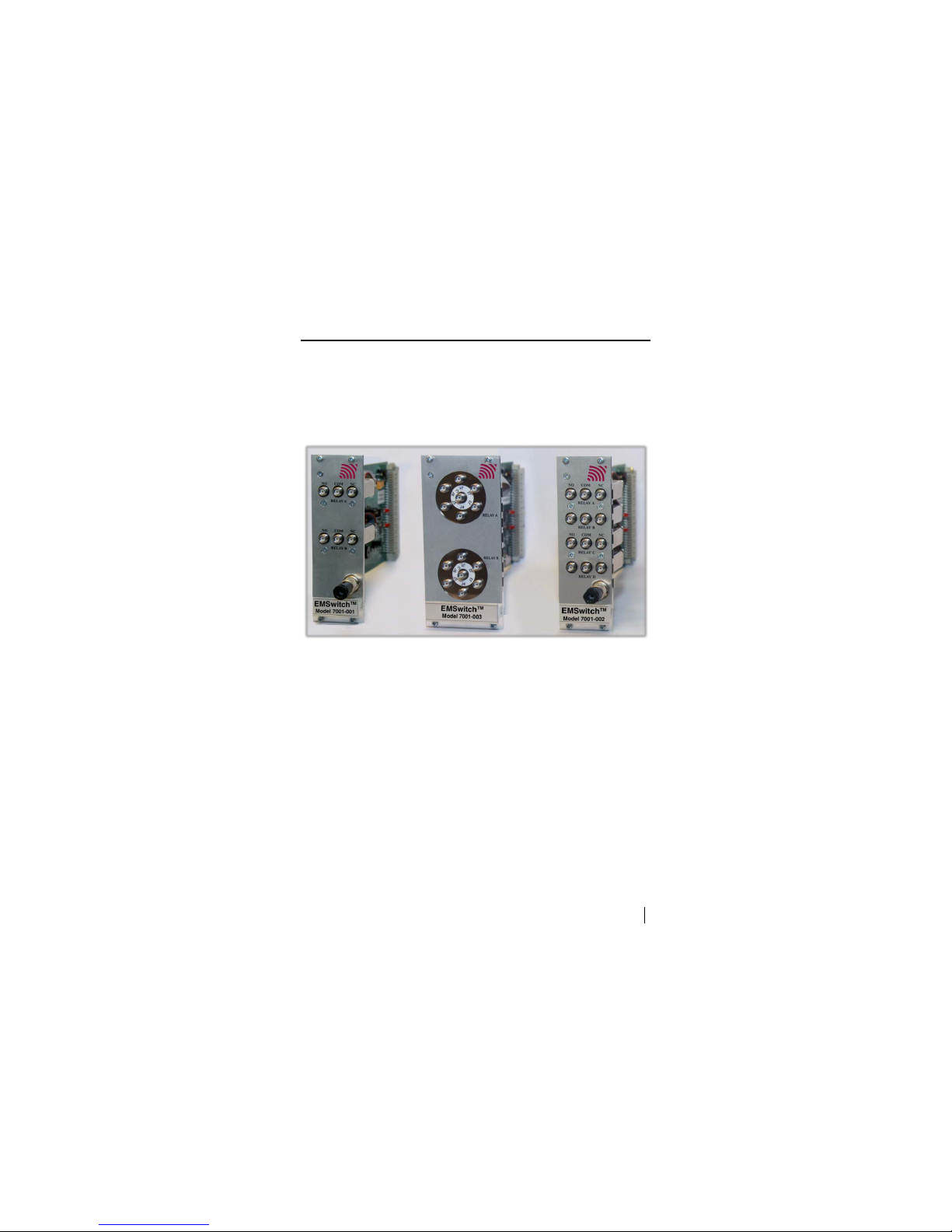
The following models of the EMSwitch card are available:
Note: The EMCenter supports any installed combination of
EMSwitch cards.
18 GHZ MODELS
• 7001-001—Two SPDT coaxial relays
• 7001-002—Four SPDT coaxial relays
• 7001-003—Two SP6T coaxial relays
• 7001-005—One SP6T coaxial relay
40 GHZ MODELS
• 7001-011—Two SPDT coaxial relays
• 7001-012—Four SPDT coaxial relays
• 7001-013—Two SP6T coaxial relays
• 7001-015—One SP6T coaxial relay
12.4 GHZ MODEL
• 7001-021—One SPDT coaxial relay
Page 9
ets-lindgren.com Introduction 9
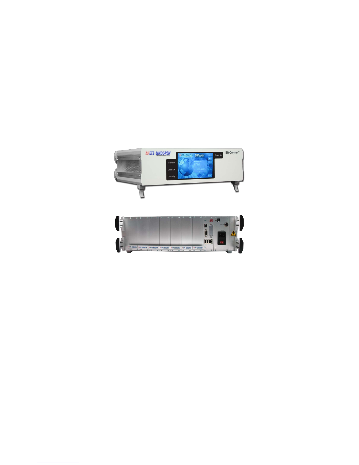
EMCenter Modular RF Platform (Required)
The EMCenter Modular RF Platform is required for operation, and is sold
separately.
Front Panel
Back Panel
The EMCenter may be controlled from a computer using these
software products:
• ETS-Lindgren TILE!™ (Totally Integrated Laboratory Environment)
• ETS-Lindgren EMQuest™ Data Acquisition and Analysis Software
• Other test automation software
Contact ETS-Lindgren for ordering information.
Page 10

10 Introduction ets-lindgren.com
EMSwitch Remote Relay (Optional)
The Model 7001-004 Remote Relay is an optional 19-inch 2U rack-mountable
device to control up to four external (coax) relays using the touchscreen on the
EMCenter or with one of these software products:
• ETS-Lindgren TILE!™ (Totally Integrated Laboratory Environment)
• ETS-Lindgren EMQuest™ Data Acquisition and Analysis Software
• Other test automation software
It has an internal power supply to power 12 VDC/28 VDC relays. For more
information on the Remote Relay, see page 21.
Standard Configuration
• EMSwitch™ RF Switch Plug-in Card
• Interlock
Note: The Model 7001-001 EMCenter Modular RF Platform is
required for operation, and is sold separately. Contact
ETS-Lindgren for ordering information.
Optional Items
• Model 7001-004 Remote Relay
Page 11

ets-lindgren.com Maintenance 11
2.0 Maintenance
CAUTION: Before performing any maintenance, follow the
information provided in Safety Information on page v.
WARNING: Maintenance of the EMSwitch card is limited to
external components such as cables or connectors.
If you have any questions concerning
maintenance, contact ETS-Lindgren
Customer Service.
Maintenance of Fiber Optics (If Used)
Fiber optic connectors and cables can be damaged from airborne particles,
humidity and moisture, oils from the human body, and debris from the connectors
they plug into. Always handle connectors and cables with care, using the
following guidelines.
CAUTION: Before performing any maintenance,
disconnect the fiber optic cables from the unit and turn off
power.
When disconnecting fiber optic cables, apply the included
dust caps to the ends to maintain their integrity.
Before connecting fiber optic cables, clean the connector
tips and in-line connectors.
Before attaching in-line connectors, clean them with
moisture-free compressed air.
Failure to perform these tasks may result in damage to the
fiber optic connectors or cables.
WARRANTY
Page 12

12 Maintenance ets-lindgren.com
Service Procedures
CONTACTING ETS-LINDGREN
Note: Please see www.ets-lindgren.com
for a list of ETS-Lindgren
offices, including phone and email contact information.
SENDING A COMPONENT FOR SERVICE
1. Contact ETS-Lindgren Customer Service to obtain a Service Request
Order (SRO).
2. Briefly describe the problem in writing. Give details regarding the
observed symptom(s) or error codes, and whether the problem is
constant or intermittent in nature. Please include the date(s), the
service representative you spoke with, and the nature of the
conversation. Include the serial number of the item being returned.
3. Package the system or component carefully. If possible, use the
original packing materials or carrying case to return a system or
system component to ETS-Lindgren.
Page 13

ets-lindgren.com Specifications 13
3.0 Specifications
Note: The first switch on each EMSwitch card can be used as a
true interlock switch.
Performance Specifications
Number of
Relays
Frequency
Band
RF Switching Capacity
7001-001 2x SPDT
18 GHz
DC to 3 GHz: 240 W
3 to 8 GHz: 150 W
8 to 12.4 GHz: 120 W
12.4 to 18 GHz: 100 W
7001-002 4x SPDT
7001-003 2x SP6T
7001-005 1xSP6T
7001-011: 2x SPDT
40 GHz
DC to 6 GHz: 80 W
6 to 12.4 GHz: 60 W
12.4 to 18 GHz: 50 W
18 to 26.5 GHz: 20 W
26.5 to 40 GHz: 10 W
7001-012: 4x SPDT
7001-013: 2x SP6T DC to 6 GHz: 40 W
6 to 12.4 GHz: 30 W
12.4 to 18 GHz: 25 W
18 to 26.5 GHz: 15 W
26.5 to 40 GHz: 5 W
7001-015: 1xSP6T
7001-021: 1x SPDT 12.4 GHz DC to 1 GHz: 700 W
1 to 2 GHz: 500 W
2 to 3 GHz: 400 W
3 to 8 GHz: 250 W
8 to 12.4 GHz: 200 W
Page 14

14 Specifications ets-lindgren.com
Lifetime Relays
• SPDT relays, SMA or 2.92mm (k): 10,000,000 cycles
• SP6T relay SMA: 5,000,000 cycles
• SP6T relay 2.92mm (k): 2,000,000 cycles
• N type relay: 1,000,000 cycles
Electrical Specifications
All EMSwitch™ RF Switch Plug-in Cards perform to the following electrical
specifications:
• Supply Voltage (Volts): Through EMCenter
Note: The supply voltage for the Model 7001-004 Remote Relay is
230 VAC.
• Power Consumption (Max Watts): 30 W
Page 15

ets-lindgren.com Specifications 15
Physical Specifications
Exterior
Dimension
RF
Connectors
Remote Control
External Relays
7001-001
One slot
SMA type
Fiber optic link
7001-002
7001-003 Two slots
7001-005 Two slots SMA type
7001-011
One slot
k type 2.92 mm
7001-012
7001-013
Two slots
7001-015
7001-021 One slot N type
7001-004
(H x W x D)
2U x 250 mm x
482.6 mm
2U x 9.8 in x 19 in
SMA type
Environmental Specifications
All EMSwitch cards perform to the following environmental specific ations:
• Temperature Range: 0
°C to 40°C (32°F to 104°F)
• Relative Humidity: 10% to 90% (non-condensing)
Page 16

16 Specifications ets-lindgren.com
This page intentionally left blank.
Page 17

ets-lindgren.com EMSwitch Card Controls and Connectors 17
4.0 EMSwitch Card Controls and Connectors
CAUTION: Before placing into operation, follow the
information provided in Safety Information on page v.
Relay Number and Contact Definitions
7001-001, 7001-002, 7001-011, 7001-012
Relay number Indicated below each relay, A to D.
Common The center SMA connector of each relay,
labeled COM.
Normally Open The left SMA connector of each relay, labeled NO.
Normally Closed The right SMA connector of each relay, labeled NC.
7001-003, 7001-005, 7001-013, 7001-015
Common The center connector; the six contacts are labeled J1
to J6.
7001-021
Common The center N connector, labeled COM.
Normally Open The bottom N connector, labeled NO.
Normally Closed The top N connector, labeled NC.
Page 18

18
EMSwitch Card Controls and
Connectors
ets-lindgren.com
Interlock
The interlock connector
provides two floating
contacts which require
shorting for the first relay.
If the interlock is open, the first relay will illuminate red on the EMCenter™
Modular RF Platform screen and the relay cannot be used. Use the supplied
connector to wire to the emergency switch of your site. Connect the two pins of
the connector.
Page 19

ets-lindgren.com EMSwitch Plug-In Card Installation 19
5.0 EMSwitch Plug-In Card Installation
CAUTION: Before connecting any components, follow the
information provided in Safety Information on page v.
CAUTION: The EMSwitch card is designed to be used
ONLY with the EMCenter. Do not use the card in
combination with any other system.
Plug-In Card Installation
Note: Due to the width of the 7001-003, 7001-005, 7001-013, and
7001-015 EMSwitch cards, two consecutive empty slots are
required for installation.
1. Determine in which empty slot in the EMCenter™ Modular RF Platform
you want to install the EMSwitch™ RF Switch Plug-in Card. Looking at
the back of the EMCenter, the slots are numbered 1 through 7 from left
to right.
2. Remove the blank panel from the slot by removing the two screws at
the top of the blank panel and t he two screws at the bottom. Remove
two consecutive blank panels if you are installing the 7001-003,
7001-005, 7001-013, or 7001-015 EMSwitch card.
3. Carefully insert the EMSwitch card into the slot(s) of the EMCenter.
Tighten the four screws.
4. Turn on the EMCenter. The EMCenter will automatically detect the
newly-installed EMSwitch card.
5. Depending on the test setup requirements, connect coaxial cables to
the relay connections on the back panel of the EMCenter.
6. Connect the EMCenter to a personal computer using USB, RS-232,
Ethernet, or IEEE (optional).
7. Plug the interlock into the connector on the back of the EMCenter.
Page 20

20 EMSwitch Plug-In Card Installation ets-lindgren.com
The card installation is complete. You can control EMSwitch through the
EMCenter touchscreen, with ETS-Lindgren TILE!™ (Totally Integrated
Laboratory Environment), ETS-Lindgren EMQuest™ Data Acquisition and
Analysis Software, and other test automation software packages. Contact
ETS-Lindgren for additional information.
Page 21

ets-lindgren.com EMSwitch Remote Relay 21
6.0 EMSwitch Remote Relay
CAUTION: Before placing into operation, follow the
information provided in Safety Information on page v.
For applications that require to switch higher power signals (>700 Watts), it is not
possible to use internal relays of the switch cards; in those cases, special
dedicated relays are needed in the test setup. For these external relays,
EMSwitch™ Model 7001-004 Remote Relay, which is capable of driving two
external relays, is available.
Model 7001-004 can drive any relay with a supply voltage of 12V, 24V, or 28V,
and from SPDT to SP6T. For each relay a driver current of 0.5A is available, or
1A if only one relay is connected.
The type of relay and the usage of indicator contacts can be configured in
software. The connection for relay 1 and relay 2 are identical.
Front and Back Panel Connectors
The front panel includes a key switch and an LED. If the EMSwitch™
Remote Relay is connected to a 220 V AC power supply and the on/off switch on
the back panel is set to the I position, you can power on the remote relay by
turning the key clockwise. The LED will illuminate.
The Remote Relay must be connected to a 220 V AC power supply via the mains
lead, connected at the AC inlet on the back panel.
Relays
You can connect four relays to the remote relay. It is possible to connect relays
with 1 input and 2, 3, 4, 5, o r 6 outputs.
To connect external relays you must use the mating connector set included with
the remote relay.
Page 22

22 EMSwitch Remote Relay ets-lindgren.com
The relay x drive connectors on the back panel of the remote relay will switch
the relays into position.
• For a 24 V relay, connect pin 1 (24 V DC output) to the Common of the
relay power terminals.
• For a 12 V relay, connect pin 2 (12 V DC output) to the Common of the
relay power terminals.
• Connect pin 3–8 to the power terminals 1–6 of the relay.
The number of power terminals to connect depends on the type of relay you use.
For example, a 1–6 relay requires all of the pins, and a 1–3 relay requires
three pins.
Readback Function
The relay x readback connectors on the back panel remote relay can veri fy if
the external relay is set into position.
1. Connect pin 1 (3v3 out) to the indicator common of the relay.
2. Connect pin 2 to the first indicator of the relay.
3. Connect pin 3 to the second indicator; continue until complete.
The number of indicator terminals to connect depends on the type of relay you
use. Pin 8 is not in use.
Set the readback function on or off in the EMCenter™ Modular RF Platform
depending on the number of relay(s) with readback function that you use.
Page 23

ets-lindgren.com EMSwitch Remote Relay 23
Set Up RS-232 Address
You can connect up to four external switch boxes to one EMCenter. Interconnect
the switch boxes with straight RS-232 cables. The DIP switches on the back
panel of the EMCenter allow you to set the individual addresses.
DIP Switch EMSwitch Remote Relay Address
1 2 3 4
On On On — Address 1
Off On On — Address 2
On Off On — Address 3
Off Off On — Address 4
Page 24

24 EMSwitch Remote Relay ets-lindgren.com
This page intentionally left blank.
Page 25

ets-lindgren.com Operation 25
7.0 Operation
CAUTION: Before placing into operation, follow the
information provided in Safety Information on page v.
CAUTION: Prior to operation, verify that the mains voltage
is within the operating range of the equipment.
Powering On and Off EMCenter
Note: For information on using the EMCenter touchscreen, s ee the
EMCenter Modular RF Platform User Manual.
POWER ON
Note: Verify all cards are installed correctly in the EMCenter.
1. Verify that the EMSwitch™ RF Switch Plug-in Card safety relay
interlock connection is closed. For more information, see page 29.
2. Plug the power cord from the mains inlet on the back panel of the
EMCenter into a power outlet.
3. Plug the interlock jack into the interlock connector on the back panel of
the EMCenter.
4. Turn the power switch located on the back panel of the EMCenter to
the on position.
Page 26

26 Operation ets-lindgren.com
5. Touch anywhere on the EMCenter screen. It will take approximately
20 seconds to boot. The Information screen will flash, and then the
Home screen will display.
Sample EMCenter Home Screen
Page 27

ets-lindgren.com Operation 27
POWER OFF
1. Press the Off button located on the EMCenter screen.
2. Press OK to switch off the system.
The standby light located on the front panel of the EMCenter will flash,
and then will illuminate steadily.
Note: When the EMCenter is in standby mode, touch the screen
anywhere to reboot.
3. Turn the power switch located on the back panel of the EMCenter to
the off position.
4. Remove the power cord from the power connector on the back panel
of the EMCenter.
5. Remove the interlock jack from the interlock connector on the
back panel of the EMCenter.
Page 28

28 Operation ets-lindgren.com
Manual Control of EMSwitch
To change relay position settings, on the Home screen press the status box to
the right of the slot number for the installed EMSwitch plug-in card. This will
display the following switch screen:
Sample Switch Screen
(Com—Common NO—Normally Open NC—Normally Closed)
Press a switch button (switch A, switc h B, and so on) to toggle between
NO and NC.
Page 29

ets-lindgren.com Operation 29
Safety Interlock Relay
Relay A on each EMSwitch plug-in card can be used as a safety interlock relay.
As long as the connector is shorted (by an external interlock switch), the relay
can be activated. However, as soon as the interlock circuit opens, relay A will
return to the idle position.
Note: If you do not want to use this relay as a safety relay, the
connector must be shorted in order to use it as a standard relay.
When the safety interlock relay is activated, the power supply to the first relay of
the card will be interrupted (fully hardware controlled), causing the relay to switch
to the normally open position. The EMCenter will detect this interlock status and
display a message. For safety reasons, the software is not able to overrule this
interlock condition.
After the interlock has been closed again, the relay will switch automatically to its
original condition.
Sample Interlock Error Screen
Page 30

30 Operation ets-lindgren.com
The interlock hardware is implemented in a redundant way for maximum safety.
The interlock relay can be used to interrupt the signal path between the signal
generator and the power amplifier. An interlock switch mounted on the door of
the test chamber can be used to activate the safety relay, preventing personnel
from being subject to high field strengths when entering the test chamber.
Relay Errors
The EMSwitch plug-in card checks for the following error conditions of the
internal relays:
1. Over temperature—A temperature sensor close to each relay checks
for excessive heating of the relay. A high temp erature error will
display if the relay temperature exceeds 85
°C (185°F).
2. Switching error—Each internal relay has a set of control contacts
which are used to check if a relay has changed position. A
switching error message will appear if this check fails.
3. Interlock open for safety interlock relay—When the interlock of
relay A is opened, this will result in a safety interlock open error.
Page 31

ets-lindgren.com EMSwitch Command Set 31
8.0 EMSwitch Command Set
See Remote Commands on page 33 for the commands that can be used with the
EMSwitch™ RF Switch Plug-in Card. Each command must include a device ID
number as the prefix; see the EMCenter Modular RF Platform User Manual for
complete information on device ID numbers.
• Terminate each command with a line feed (LF, shown as \n in
command syntax).
• Each response from the device is terminated with a line
feed (LF, shown as \n in command syntax).
Examples
EXAMPLE 1: REQUEST SOFTWARE VERSION
To request the software version of the EMSwitch card with device ID number 1:
S1:VERSION_SW?
EXAMPLE 2: SET INTERNAL RELAY
To set the internal relay A from the EMSwit ch card with device ID number 1 to
normally open:
S1:INT_RELAY_A_NO
Page 32

32 EMSwitch Command Set ets-lindgren.com
EXAMPLE 3: SET EXTERNAL RELAY
To set the external relay 3 from the EMSwitch Remote Relay with address 4,
connected to the EMSwitch card at slot 2, position 5:
S2:N14RELAY_3_5
S = Device character of EMSwitch card
2 = Board number of EMSwitch card
N1 = Indicates EMSwitch card to pass message to external
interface
4 = Address of EMSwitch Remote Relay (configurable with
DIP switches)
RELAY_ = Message to switch relay
3 = Number of switch on EMSwitch Remote Relay
_ = Separator
5 = Instruction to put switch in position 5
Page 33

ets-lindgren.com EMSwitch Command Set 33
Remote Commands
Note: If you receive an error code in response to a command, see
page 37 for a list of error codes.
COMMAND SET—COMMON TO ALL EMSWITCH MODELS
Command / Description Reply
*IDN?
Request device identification.
Model, Version X.Y.Z
Example:
ETS-Lindgren, EMSwitch
7001-003, 3.5.10
LOCAL
Return to local mode, the local display is
used to set items .
—
RESET/n
Reset (clear the current error).
—
ID_NUMBER?
Request unique identifier number.
x.x.x.x.x.x.x.x
VERSION_SW?
Returns the software version number.
x.y.z OR x.y OR x
VERSION_HW?
Returns the hardware version number.
x.y.z OR x.y OR x
Page 34

34 EMSwitch Command Set ets-lindgren.com
COMMAND SET—MODEL-SPECIFIC: 7001-001, 7001-002, 7001-011,
7001-012, 7001-021
Description / Command Reply
Returns the status of internal relay 1 (2, 3, or 4).
INT_RELAY_A?
INT_RELAY_B?
INT_RELAY_C?
INT_RELAY_D?
NO or NC
Sets the internal relay A (B, C, or D) to NO.
INT_RELAY_A_NO
INT_RELAY_B_NO
INT_RELAY_C_NO
INT_RELAY_D_NO
NO or NC
Sets the internal relay A (B, C, or D) to NC.
INT_RELAY_A_NC
INT_RELAY_B_NC
INT_RELAY_C_NC
INT_RELAY_D_NC
NO or NC
Returns the analog temperature of the internal
relay A ( B, C, or D).
INT_TEMPERATURE_A?
INT_TEMPERATURE_B?
INT_TEMPERATURE_C?
INT_TEMPERATURE_D?
100
Three ASCII
characters with
temperature in
degrees Celsius
Page 35

ets-lindgren.com EMSwitch Command Set 35
Description / Command Reply
Set switch 2 of EMSwitch Remote Relay 1 to
position 3.
N11RELAY_2_3
OK
Set switch 2 of EMSwitch Remote Relay 2 to
position 4.
N12RELAY_2_4
OK
Get position of switch 2 of EMSwitch Remote
Relay 1.
N11RELAY_2?
One of the following:
!, 2, 3, 4, 5, 6
Get position of switch 3 of EMSwitch Remote
Relay 2.
N12RELAY_3?
One of the following:
!, 2, 3, 4, 5, 6
Set switch type of switch 3 of EMSwitch Remote
Relay 2 to 1 to 2, 1 to 3, 1 to 4, 1 to 5, or 1 to 6.
N12RELAYTYPE_3_2
N12RELAYTYPE_3_3
N12RELAYTYPE_3_4
N12RELAYTYPE_3_5
N12RELAYTYPE_3_6
OK
Get switch type of switch 3 of EMSwit ch Remote
Relay 2.
N12RELAYTYPE_2?
One of the following:
2, 3, 4, 5, 6
Disable readback to switch 3 of EMSwitch Remote
Relay 2.
N12READBACK_3_0
OK
Enable readback to switch 3 of EMSwitch Remote
Relay 2.
N12READBACK_3_1
OK
Get readback status to switch 3 of EMSwitch
Remote Relay 2.
N12READBACK_3?
0 (disabled) OR
1 (enabled)
Page 36

36 EMSwitch Command Set ets-lindgren.com
COMMAND SET—MODEL-SPECIFIC: 7001-003, 7001-005, 7001-013,
7001-015
Description / Command Reply
Returns status of internal relay A or B.
INT_RELAY_A?
INT_RELAY_B?
One of the following:
1, 2, 3, 4, 5, 6
Sets internal relay A or B.
INT_RELAY_A_1
INT_RELAY_A_2
INT_RELAY_A_3
INT_RELAY_A_4
INT_RELAY_A_5
INT_RELAY_A_6
One of the following:
1, 2, 3, 4, 5, 6
Page 37

ets-lindgren.com EMSwitch Command Set 37
Error Codes
Error Code Description
ERROR_201 Switch error while trying to switch to NC (internal relays only)
ERROR_202 Switch error while trying to switch to NO (internal relays only)
ERROR_203 Temperature error NC (internal relays only)
ERROR_204 Temperature error NO (internal relays only)
ERROR_205 Interlock error (internal relays only)
ERROR_206 Error Switch A
ERROR_207 Error Switch B
ERROR_208 Error Switch
ERROR_209 Error external card
ERROR_210 Error no external card connected
ERROR_211 Error status unknown
ERROR_215 Error out of config
Page 38

38 EMSwitch Command Set ets-lindgren.com
This page intentionally left blank.
Page 39

ets-lindgren.com Typical Data 39
9.0 Typical Data
Specifications of plug-in cards with SMA connectors
Specification SMA, 18 GHZ, SPDT relays
Life Time 10.000. 000 cycles
Frequency GHz 0 to 3 3 to 8 8 to 12.4 12.4 to 18
VSWR 1, 10 1, 20 1, 20 1, 40
Insertion
Loss
dB 0, 15 0, 20 0, 25 0, 35
Isolation dB 80 75 65 60
Average
Power
W 240 150 120 100
Specification SMA, 18 GHZ, SP6T relays
Life Time 5.000.000 cycles
Frequency GHz 0 to 3 3 to 8 8 to 12.4 12.4 to 18
VSWR 1, 20 1, 30 1, 40 1, 50
Insertion Loss dB 0,20 0, 30 0, 40 0, 50
Isolation dB 80 75 65 60
Average
Power
W 240 150 120 100
Page 40

40 Typical Data ets-lindgren.com
Specifications of plug-in cards with 2.92 mm connectors
Specification K 2.92 mm, 40 GHz, SPDT relays
Life Time 10.000. 000 cycles
Frequency GHz 0 to 6 6 to
12.4
12.4 to
18
18 to
26.5
26.5 to
40
VSWR 1, 30 1, 40 1, 50 1, 70 1, 9
Insertion
Loss
dB 0, 30 0, 40 0, 50 0, 70 0, 8
Isolation dB 70 60 60 55 50
Average
Power
W 80 60 50 20 10
Specification K 2.92 mm, 40 GHz, SP6T relays
Life Time 2.000.000 cycles
Frequency GHz 0 to 6 6 to
12.4
12.4 to
18
18 to
26.5
26.5 to
40
VSWR 1, 30 1, 40 1, 50 1, 70 2, 2
Insertion
Loss
dB 0, 20 0, 40 0, 50 0, 70 1, 1
Isolation dB 70 60 60 55 50
Average
Power
W 40 30 25 15 5
Page 41

ets-lindgren.com Typical Data 41
Power Handling
The RF power rating is the capability of handling RF power (CW power) through
closed contacts. The RF power should be removed (turned off) before switching
the relay.
Power ratings assume the following specifications; see the power handling
data chart on page 42.
• Unity VSWR (matched load)
• Room temperature (25°C / 77°F)
• Sea level pressure (14.7 psi)
• Cold switching
Changes to these specifications require power derating; see the VSWR data
chart on page 43.
Page 42

42 Typical Data ets-lindgren.com
Page 43

ets-lindgren.com Typical Data 43
VSWR
The average power input must be reduced for load VSWR. above 1:1.
Page 44

44 Typical Data ets-lindgren.com
This page intentionally left blank.
Page 45

ets-lindgren.com Warranty 45
Appendix A: Warranty
Scope and Duration of Warranties
Seller warrants to Buyer that the Products to be delivered hereunder will be (1)
free from defects in material, manufacturing workmanship, and title, and (2)
conform to the Seller’s applicable product descriptions and specifications, if any,
contained in or attached to Seller’s quotation. If no product descriptions or
specifications are contained in or attached to the quotation, Seller’s applicable
product descriptions and specifications in effect on the date of shipment shall
apply. The criteria for all testing shall be Seller’s applicable product specifications
utilizing factory-specified calibration and test procedures and instruments.
All product warranties, except the warranty of title, and all remedies for warranty
failures are limited to three years.
Product Warranted Duration of Warranty Period
EMSwitch™ RF Switch Plug-in Card 3 Years
Any product or part furnished to Buyer during the warranty period to correct a
warranty failure shall be warranted to the extent of the unexpired term of the
warranty applicable to the repaired or replaced product.
The warranty period shall commence on the date the product is delivered to
Buyer; however, if Seller assembles the product, or provides technical direction
of such assembly, the warranty period for such product shall commence on the
date the assembly of the product is complete. Notwithstanding the foregoing, in
the event that the assembly is delayed for a total of thirty (30) days or more from
the date of delivery for any reason or reasons for which Seller is not responsible,
the warranty period for such product may, at Seller’s options, commence on the
thirtieth (30th) day from the date such product is delivered to Buyer. Buyer shall
promptly inspect all products upon delivery. No claims for shortages will be
allowed unless shortages are reported to Seller in writing within ten (10) days
after delivery. No other claims against Seller will be allowed unless asserted in
writing within thirty (30) days after delivery (or assembly if the products are to be
assembled by Seller) or, in the case of alleged breach of warranty, within the
applicable warranty period.
Page 46

46 Warranty ets-lindgren.com
Warranty Exclusions
Except as set forth in any applicable patent indemnity, the foregoing warranties
are exclusive and in lieu of all other warranties, whether written, oral, express,
implied, or statutory . EXCEPT AS EXPRESSLY STATED ABOVE, SELLER
MAKES NO WARRANTY, EXPRESS OR IMPLIED, BY STATUTE OR
OTHERWISE, WHETHER OF MERCHANTABILITY OR FITNESS FOR ANY
PARTICULAR PURPOSE OR USE OR OTHERWISE ON THE PRODUCTS, OR
ON ANY PARTS OR LABOR FURNISHED DURING THE SALE, DELIVERY OR
SERVICING OF THE PRODUCTS. THERE ARE NO WARRANTIES WHICH
EXTEND BEYOND THE DESCRIPTION ON THE FACE HEREOF.
Warranty coverage does not include any defect or performance deficiency
(including failure to conform to product descriptions or specifications) which
results, in whole or in part, from (1) negligent storage or handling of the product
by Buyer, its employees, agents, or contractors, (2) failure of Buyer to prepare
the site or provide an operating environmental condition in compliance with any
applicable instructions or recommendations of Seller, (3) absence of any product,
component, or accessory recommended by Seller but omitted at Buyer’s
direction, (4) any design, specification, or instruction furnished by Buyer, its
employees, agents or contractors, (5) any alteration of the product by persons
other than Seller, (6) combining Seller’s product with any product furnished by
others, (7) combining incompatible products of Seller, (8) interference with the
radio frequency fields due to conditions or causes outside the product as
furnished by Seller, (9) improper or extraordinary use of the product, or failure to
comply with any applicable instructions or recommendations of Seller including
maintenance, calibration and cleaning procedures and intervals, or (10) acts of
God, acts of civil or military authority, fires, floods, strikes or other labor
disturbances, war, riot, or any other causes beyond the reasonable control of
Seller.
This warranty does not include (1) batteries, (2) cables, (3) gasket,
(4) fingerstock, or any item that is designed to be consumable. Seller does not
warranty products of others which are not included in Seller’s published price
lists.
Page 47

ets-lindgren.com Warranty 47
Buyer’s Remedies
If Seller determines that any product fails to meet any warranty during the
applicable warranty period, Seller shall correct any such failure by either, at its
option, repairing, adjusting, or replacing without charge to Buyer any defective or
nonconforming product, or part or parts of the product. Seller shall have the
option to furnish either new or exchange replacement parts or assemblies.
Warranty service shall be performed at the Seller’s factory, or the Buyer’s site at
the sole discretion of the Seller. Within the warranty period, the Buyer shall be
responsible for all transportation to the Seller’s factory, and the Seller shall be
responsible for transportation of goods to the Buyer’s site.
Within the contiguous 48 United States, warranty service performed during the
applicable warranty period will be performed without charge to Buyer during
Seller’s normal business hours. After the warranty period, service will be
performed at Seller’s prevailing service rates. Subject to the availability of
personnel, after-hours service is available upon request at an additional charge.
Outside the contiguous 48 United States, travel and per diem expenses, when
required, shall be the responsibility of the Buyer, or End User, whichever is
applicable regardless of the warranty period.
The remedies set forth herein are conditioned upon Buyer promptly notifying
Seller within the applicable warranty period of any defect or non-conformance
and making the product available for correction.
Page 48

48 Warranty ets-lindgren.com
The preceding paragraphs set forth Buyer’s exclusive remedies and Seller’s sole
liability for claims based on failure of the products to meet any warranty, whether
the claim is in contract, warranty, tort (including negligence and strict liability) or
otherwise, and however instituted, and, upon the expiration of the applicable
warranty period, all such liability shall terminate. IN NO EVENT SHALL SELLER
BE LIABLE TO BUYER FOR ANY SPECIAL, INDIRECT, INCIDENTAL OR
CONSEQUENTIAL DAMAGES OF ANY KIND ARISING OUT OF, OR AS A
RESULT OF, THE SALE, DELIVERY, NON-DELIVERY, SERVICING,
ASSEMBLING, USE OR LOSS OF USE OF THE PRODUCTS OR ANY PART
THEREOF, OR FOR ANY CHARGES OR EXPENSES OF ANY NATURE
INCURRED WITHOUT SELLER’S WRITTEN CONSENT DESPITE ANY
NEGLIGENCE ON BEHALF OF THE SELLER. IN NO EVENT SHALL SELLER’S
LIABILITIES UNDER AN Y CLAIM MADE BY BUYER EXC EED THE
PURCHASE PRICE OF THE PRODUCT IN RESPECT OF WHICH DAMAGES
ARE CLAIMED. This agreement shall be construed in accordance with laws of
the State of Texas. In the event that any provision hereof shall violate any
applicable statute, ordinance, or rule of law, such provision shall be ineffective to
the extent of such violation without invalidating any other provision hereof.
Any controversy or claim arising out of or relating to the sale, delivery, nondelivery, servicing, assembling, use or loss of use of the products or any part
thereof or for any charges or expenses in connection therewith shall be settled in
Austin, Texas by arbitration in accordance with the Rules of the American
Arbitration Association, and judgment upon the award rendered by the Arbitrator
may be entered in either the Federal District Court for the Western District of
Texas or the State District Court in Austin, Texas, all of the parties hereto
consenting to personal jurisdiction of the venue of such court and hereby waive
the right to demand a jury trial under any of these actions.
Page 49

ets-lindgren.com EC Declaration of Conformity 49
Appendix B: EC Declaration of Conformity
ETS-Lindgren Inc. declares these products to be in conformity with the following
standards, following the provisions of EMC-Directive 2004/108/EC:
EMSwitch RF Switc h Plug-In Card
Emission: EN 61326-1:2006, Class B
Electrical equipment for measurement, control, and laboratory use.
Immunity: EN 61326-1:2006, Industrial level, performance criteria A
Electrical equipment for measurement, control, and laboratory use.
Technical Construction Files are available upon request.
 Loading...