

Page 1
Model 4630
Archived 3/18/10
REFRAD
Reference Radiator
MANUAL
© EMC TEST SYSTEMS, L.P. – MARCH 2002 REV F – PN 399214
LICENCED FROM:
FORSCHUNGSZENTRUM SEIBERSDORF
Page 2

MODEL 4630 REFRAD REFERENCE RADIATOR
Archived 3/18/10
EMC Test Systems, L.P. reserves the right to make changes to any product described herein in order to
improve function, design or for any other reason. Nothing contained herein shall constitute EMC Test
Systems, L.P. assuming any liability whatsoever arising out of the application or use of any product or
circuit described herein. EMC Test Systems, L.P. does not convey any license under its patent rights or th e
rights of others.
© Copyright 2002 by EMC Test Systems, L.P. All Rights Reserved.
No part of this document may be copied by any means
without written permission from EMC Test Systems, L.P.
E-MAIL & INTERNET
Support@ets-lindgren.com
http://www.ets-lindgren.com
USA
1301 Arrow Point Dr., Cedar Park, TX 78613
P.O. Box 80589, Austin, TX 78708-0589
Tel 512.531.6400 Fax 512.531.6500
FINLAND
Euroshield OY
Mekannikontie 1
27510, Eura, Finland
Tel 358.2.838.3300
Fax 358.2.865.1233
SINGAPORE
Lindgren RF Enclosures Asia-Pacific
87 Beach Road
#06-02 Chye Sing Building
Singapore 189695
Tel 65.536.7078 Fax 65.536.7093
© EMC TEST SYSTEMS, L.P. – MARCH 2002
REV F – PN 399214
Page 3

MODEL 4630 REFRAD REFERENCE RADIATOR
Archived 3/18/10
Table of Contents
INTRODUCTION............................................................................................................. 1
T
YPICAL USE ................................................................................................................... 1
COMB GENERATOR .......................................................................................................... 1
Operation of the Comb Generator .............................................................................. 1
Battery Charger .......................................................................................................... 2
REMOTE CONTROL UNIT .................................................................................................. 3
TECHNICAL DATA ........................................................................................................ 4
COMB GENERATOR .......................................................................................................... 4
Power Supply .............................................................................................................. 4
Output Signal – Comb Spectrum ................................................................................. 4
Remote Control ........................................................................................................... 4
Temperature Range ..................................................................................................... 4
REMOTE CONTROL ........................................................................................................... 6
Power Supply .............................................................................................................. 6
GPIB Bus .................................................................................................................... 6
GPIB Command Set .................................................................................................... 6
GPIB Examples ........................................................................................................... 7
Fiber Optic Out ........................................................................................................... 7
Temperature Range ..................................................................................................... 7
OPERATION INVENTORY .................................................................................................. 7
ACCESSORIES ................................................................................................................... 8
Transmit Antennas ...................................................................................................... 8
Tripod Mounting Accessories ..................................................................................... 8
Fiber Optic Link .......................................................................................................... 8
Coaxial Adapter .......................................................................................................... 8
Reference Cable and Attenuator ................................................................................. 8
(Not Supplied with System) ......................................................................................... 8
APPLICATIONS .............................................................................................................. 9
ITE INTERCOMPARISON .................................................................................................. 9
S
NORMALIZED SITE ATTENUATION ................................................................................... 9
SYSTEM CHECKOUT ....................................................................................................... 10
C
ABLE LOSS ................................................................................................................... 11
CHAMBER FACTOR ......................................................................................................... 11
FUNCTIONAL DESCRIPTION ................................................................................... 12
OMB GENERATOR ........................................................................................................ 12
C
R
EMOTE CONTROL UNIT ................................................................................................ 12
CERTIFICATE ............................................................................................................... 14
WARRANTY STATEMENT ........................................................................................ 15
© EMC TEST SYSTEMS, L.P. – MARCH 2002
REV F – PN 399214
Page 4
MODEL 4630 REFRAD REFERENCE RADIATOR
T
Archived 3/18/10
NOTICE: This product and related documentation must be reviewed for
familiarization with safety markings and instructions before operation.
SAFETY SYMBOL DEFINITIONS
REFER TO MANUAL
When product is marked with this symbol refer to instruction manual for
!
CAUTION
GENERAL SAFETY CONSIDERATIONS
S
U
E
F
F
E
U
S
WARRANTY
FUSE
2A:250V
G P I B
G P I B
G P I B
G P I B
additional information.
HIGH VOLTAGE
Indicates the presence of hazardous voltage. Unsafe practices could
result in severe personal injury or death.
PROTECTIVE EARTH GROUND (SAFETY GROUND)
Indicates protective earth terminal. You should provide an uninterruptible
safety earth ground from the main power source to the product input
wiring terminals, power cord, or supplied power cord set.
CAUTION
Denotes a hazard. Failure to follow instructions could result in minor
personal injury and/or property damage. Included text gives proper
procedures.
BEFORE POWER IS APPLIED TO THIS INSTRUMENT, GROUND IT
PROPERLY through the protective conductor of the AC power cable to a
power source provided with protective earth contact. Any interruption of
the protective (grounding) conductor, inside or outside the instrument, or
disconnection of the protective earth terminal could result in personal
injury.
BEFORE SERVICING: CONTACT EMC TEST SYSTEMS – servicing (or
modifying) the unit by yourself may void your warranty. If you attempt to
service the unity by yourself, disconnect all electrical power before
starting. There are voltages at many points in the instrument which
could, if contacted cause personal injury. Only trained service personnel
should perform adjustments and/or service procedures upon this
instrument. Capacitors inside this instrument may still be CHARGED
even when the instrument is disconnected from its power source.
TO AVOID A SAFETY HAZARD, replace fuses with the same current
rating and type (normal blow, time delay, etc.). Order any replacement
parts direct from ETS.
TO AVOID UNDUE MECHANICAL STRESS on the GPIB I/O
CONNECTOR, limit connector stacking to no more than three cables on
one connector.
© EMC TEST SYSTEMS, L.P. – MARCH 2002
REV F – PN 399214
ONLY QUALIFIED PERSONEL should operate (or service) this
equipment.
Page 5

MODEL 4630 REFRAD REFERENCE RADIATOR Introduction
Archived 3/18/10
INTRODUCTION
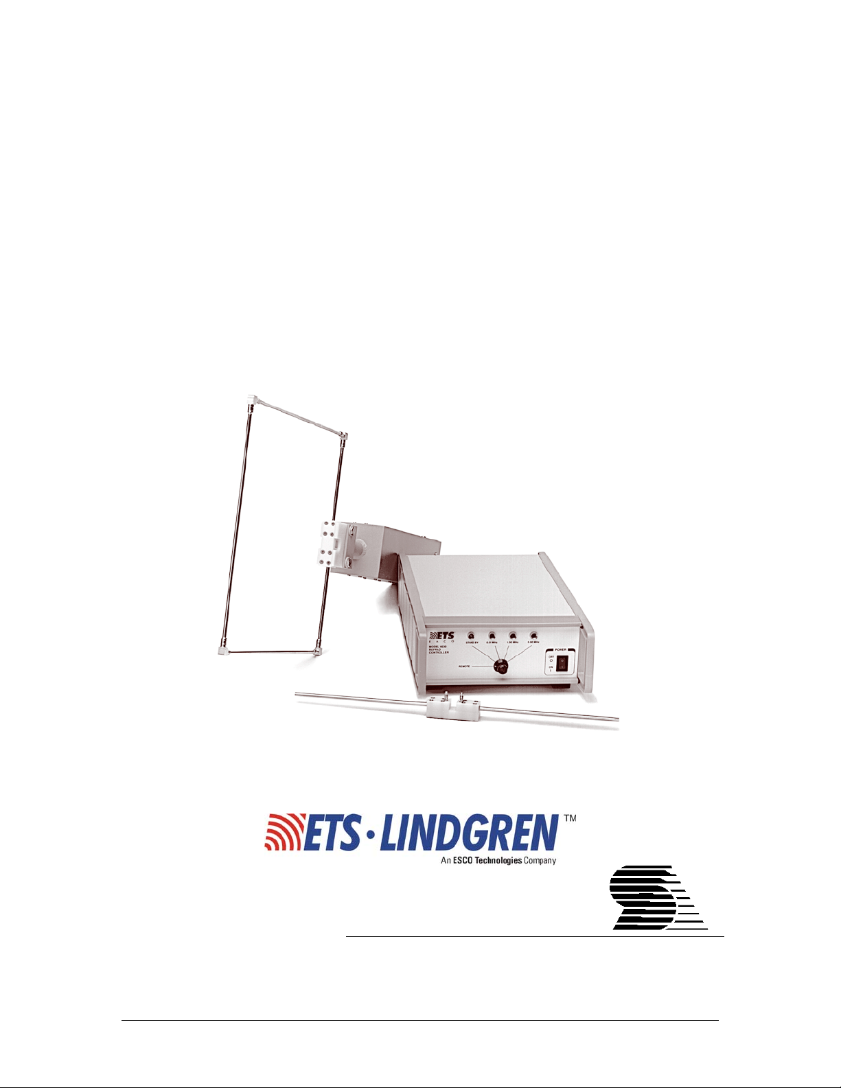
The EMC Test Systems Model 4630 Refrad Reference Radiator is
a precise highly stable field strength transfer standards with
selectable frequency spacings over the range of 10 kHz to 1 GHz.
The system consists of a small battery powered comb generator
with a loop and two dipole transmit antennas, a coaxial output
adapter, and a remote control unit with GPIB interface.
TYPICAL USE
1. Set up comb generator and remote control unit.
2. Connect both devices via the fiber optic cable. You may clean
the connectors with a soft lint-free cloth if necessary.
3. The comb generator has to be operated in remote mode to be
used with the remote control unit.
4. Operation by a remote computer is possible. (see the ‘Remote
Control Unit’ section)
5. The comb generator should be recharged after each use.
(battery charger with cable and power supply supplied)
COMB GENERATOR
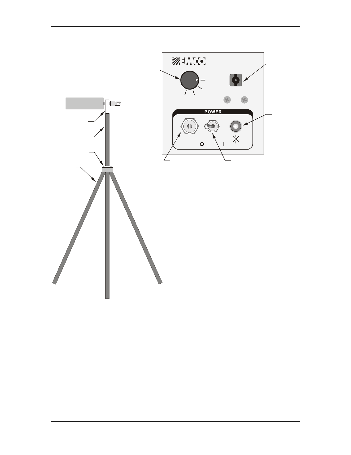
OPERATION OF THE COMB GENERATOR
1. Plug the selected antenna elements into the balun on the comb
generator.
2. For horizontal and vertical antenna polarization, use the
supplied support base, support rod, and clamp bock for tripod
mounting.
3. Select any comb spectrum by rotating the front panel knob to
the desired setting (0.01 MHz, 1.0 MHz, or 5.0 MHz). To
transfer to the remote control unit rotate the knob to the
“REMOTE” setting.
4. To recharge the comb generator after use, put the ON/OFF
switch in the CHARGE/OFF position and insert the battery
charger output plug into the comb generator’s input socket.
© EMC TEST SYSTEMS, L.P. – MARCH 2002 1
REV F – PN 399214
Page 6
Introduction MODEL 4630 REFRAD REFERENCE RADIATOR
Archived 3/18/10
REFRAD
Comb Generator
Clamp block
Rotar y sw i tch
for manua l selection
of a comb spectrum
REMOTE
or mode
1.0 MHz5.0 MHz
MODEL 4630
REFRAD COMB GENERATOR
REMOTE
0.01 MHz
F.O. INP UT
Fiber optic input
for remote control
LED
power on
indicator
Support rod
Support base
Tripod
CHARGE OFF
Battery charge r in put
/
ON
FIGURE 1. REFRAD Comb Generator
Front Panel.
Insert the battery charger output plug into the
comb generator’s input socket.
(see the following Battery Charger topic for
more information)
FIGURE 2. Tripod Mounting of REFRAD Comb Generator
BATTERY CHARGER
There is one red LED and one green LED on the body of the
separate battery charger. The “Power On” LED illuminates when
the chargers is plugged into the 20V DC power supply. Power is
supplied to the supply via the IEC 302-type power inlet. The
supplied safety-certified power cord should always be used to
maintain safe operation.
A solid red LED indicates fast charge mode. When the red LED
flashes, the charger is operating in a pre-charge mode. As the
ON / OFF switch
2 © EMC TEST SYSTEMS, L.P. – MARCH 2002
REV F – PN 399214
Page 7

MODEL 4630 REFRAD REFERENCE RADIATOR Introduction
Archived 3/18/10
battery nears full charge, the charge will begin to operate in a
TOP-OFF/TRICKLE mode. This is indicated by the green LED.
The power supply uses a green LED to indicate that power is
applied. In case of a fault condition, the green LED with be
extinguished.
NOTE: The REFRAD comb generator is not designed to operate
using the battery charger as a power source.
REMOTE CONTROL UNIT
1. Connect the remote control unit to the GPIB-bus.
2. Connect the 9 V DC plug-in power supply.
Note: Use only the power supply included with the unit.
3. With the comb generator set to “REMOTE” mode, the front
panel knob on the remote control unit may be used to select
any comb spectrum manually. The comb spectrum may also be
selected by a remote computer connected to the GPIB (IEEE-
488) bus with the control knobs on both the comb generator
and remote control unit set to “REMOTE”. Note settings in to
illustration below.
LEDs
(for selection indication)
© EMC TEST SYSTEMS, L.P. – MARCH 2002 3
REV F – PN 399214
MODEL 4630
REFRAD REM OTE
CONTROL UNIT
FIGURE 3. REFRAD Remote Control Unit Front Panel.
STAND BY
REMOTE
Rotary switch
(for manual selection of a comb spectrum,
REMOTE STAND BY
0.01 MHz 1.00 MHz 5.00 MHz
mode, or mode)
POWER
ON
OFF
ON / OFF switch
Page 8

Technical Data MODEL 4630 REFRAD REFERENCE RADIATOR
Archived 3/18/10
TECHNICAL DATA
COMB GENERATOR
POWER SUPPLY
One (1), internal 12 VNIMh 3.5 Ah.
Factory serviceable only.
OUTPUT SIGNAL – COMB SPECTRUM
BALUN USED
RANGE
(MHz)
C 0.01-1 0.01 -17 to -20
B 1-100 1 -10 to –18
A 100-1000 5 -10 to –30
LINE SPACING
(MHz)
OUTPUT
POWER
Per line,
typical (dBm)
CAUTION For measuring the direct output signal, the comb
generator has to be connected via an attenuator (attenuation 30 dB)
to protect the test receiver or spectrum analyzer.
REMOTE CONTROL
Connection is made with Hewlett Packard low-loss plastic fiber
optic cable with simplex-type connectors.
TEMPERATURE RANGE
+5 degrees to +30 degrees C.
4 © EMC TEST SYSTEMS, L.P. – MARCH 2002
REV F – PN 399214
Page 9

MODEL 4630 REFRAD REFERENCE RADIATOR Technical Data
Archived 3/18/10
10 kHz SPECTRUM
1 MHz SPECTRUM
5 MHz SPECTRUM
0
-10
-20
-30
-40
-50
-60
PM (dBm)
-70
-80
-90
-100
-110
0.01 0.1 1
0
-10
-20
-30
-40
-50
-60
PM (dBm)
-70
-80
-90
-100
-110
1 10 100
0
-10
-20
-30
-40
-50
-60
PM (dBm)
-70
-80
-90
-100
-110
10 100 1,000
FREQUENCY (MHz)
FREQUENCY (MHz)
FREQUENCY (MHz)
FIGURE 4. Typical comb generator output spectrum in the three frequency ranges.
© EMC TEST SYSTEMS, L.P. – MARCH 2002 5
REV F – PN 399214
Page 10

Technical Data MODEL 4630 REFRAD REFERENCE RADIATOR
Archived 3/18/10
REMOTE CONTROL
POWER SUPPLY
GPIB
ADDR
10 OFF ON OFF ON OFF
11 OFF ON OFF ON ON
12 OFF ON ON OFF OFF
13 OFF ON ON OFF ON
14 OFF ON ON ON OFF
15 OFF ON ON ON ON
16 ON OFF OFF OFF OFF
17 ON OFF OFF OFF ON
18 ON OFF OFF ON OFF
19 ON OFF OFF ON ON
20 ON OFF ON OFF OFF
21 ON OFF ON OFF ON
22 ON OFF ON ON OFF
23 ON OFF ON ON ON
24 ON ON OFF OFF OFF
25 ON ON OFF OFF ON
26 ON ON OFF ON OFF
27 ON ON OFF ON ON
28 ON ON ON OFF OFF
29 ON ON ON OFF ON
30 ON ON ON ON OFF
31 ON ON ON ON ON
A5 A4 A3 A2 A1
0 OFF OFF OFF OFF OFF
1 OFF OFF OFF OFF ON
2 OFF OFF OFF ON OFF
3 OFF OFF OFF ON ON
4 OFF OFF ON OFF OFF
5 OFF OFF ON OFF ON
6 OFF OFF ON ON OFF
7 OFF OFF ON ON ON
8 OFF ON OFF OFF OFF
9 OFF ON OFF OFF ON
Address - Switch setting table
Plug in power supply, 9V DC, 50 mA.
GPIB BUS
Selection of address
The GPIB address (DEFAULT) is changed by
removing the top of the remote control unit and
selecting the desired switch settings on the GPIB
interface boards (see diagram below). The table relates
the switch setting to the actual address. (Note that
moving the switch up turns it on and pushing it down
turns it off.)
GPIB COMMAND SET
The GPIB commands are listed in the following table:
LINE SPACING
GPIB
COMMAND
Standby “0”
0.01 MHz “1”
1 MHz “2”
5 MHz “3”
NOTE: The commands have to sent without
termination character(s) and without “CRIF”.
FIGURE 5. Remote Control Unit System Diagram.
6 © EMC TEST SYSTEMS, L.P. – MARCH 2002
REV F – PN 399214
Page 11

MODEL 4630 REFRAD REFERENCE RADIATOR Technical Data
Archived 3/18/10
GPIB EXAMPLES
ibwrt”0” sets STBY MODE
ibwrt”1” sets 10 kHz MODE
ibwrt“2” sets 1 MHz MODE
ibwrt“3” sets 5 MHz MODE
FIBER OPTIC OUT
Hewlett Packard Simplex connector
TEMPERATURE RANGE
+5 degrees to +30 degrees C.
OPERATION INVENTORY
Comb Generator Support Base
Remote Control Unit Support Block
10 m Fiber Optic Cable Clamp Block
Power Supply 9 VDC Battery Charger with Cable
Square Loop Antenna Assembly Coax Adapter
Long Dipole Antenna Elements
Balun Assembly
Short Dipole Antenna Elements
Balun Assembly
REFRAD Manual
© EMC TEST SYSTEMS, L.P. – MARCH 2002 7
REV F – PN 399214
Page 12

Technical Data MODEL 4630 REFRAD REFERENCE RADIATOR
Archived 3/18/10
ACCESSORIES
TRANSMIT ANTENNAS
The system includes three antennas:
Long dipole antenna, element length 650mm
(for use with 10 kHz spacing)
Square loop, side length 300mm
(use for generating magnetic field)
Short dipole antenna, element length 200mm
(for use with 1 MHz and 5 MHz spacing)
TRIPOD MOUNTING ACCESSORIES
The following tripod accessories are included with the system:
Support rod
Support base
Clamp block
FIBER OPTIC LINK
Fiber optic link: Simplex connectors, standard length: 10m. Fiber
optic link
COAXIAL ADAPTER
Provides a means to adapt the output of the comb generator to a
type “N” coaxial connector.
REFERENCE CABLE AND ATTENUATOR
(NOT SUPPLIED WITH SYSTEM)
Reference cable: Coaxial cable, length 25 cm.
Connectors: Type BNC male – Type N male
Attenuator:30 dB, BNC
8 © EMC TEST SYSTEMS, L.P. – MARCH 2002
REV F – PN 399214
Page 13

MODEL 4630 REFRAD REFERENCE RADIATOR APPLICATIONS
Archived 3/18/10
APPLICATIONS
The following applications assume the use of CalStan software. It
allows automatic measurements, data processing and
documentation of test results. See CalStan’s manual for further
information. CalStan is available from:
Austrian Research Center
Division of Electronics Electromagnetic Compatibility
Radio Frequency – Engineering Section
A-2444 Seibersdorf, Austria. Tel: +432254-780-2800.
emc@fzmarl.arcs.ac.at
Other applications are possible using the REFRAD as a fieldstrength transfer standard.
For outdoor operations, precautions have to be taken in order to
avoid radio interference.
SITE INTERCOMPARISON
Intercomparisions are demanded by EN 45001 for all accredited
test laboratories, but are useful for all other laboratories as well.
To carry out an intercomparision, the reference radiator REFRAD
is set up in the center of the turntable. By analogy to NSA
measurements, the REFRAD is operated with dipole and loop
antennas at two heights above ground in horizontal and vertical
polarization. The frequency range is 30-1000 MHz. This procedure
requires no more than half a day. Computer control assures
efficient, fault less operation and the data is automatically
processed. Differences with respect to data from other sites can be
plotted and analyzed.
NORMALIZED SITE ATTENUATION
Normalized site attenuation (NSA) measurements are carried out
according to ANSI 63.4 and CISPR/A(Secr.)109, July, 1991. The
frequency range is 30 - 1000 MHz. The “volume method” has to
be applied: The transmilt antenna with the reference radiator
© EMC TEST SYSTEMS, L.P. – MARCH 2002 9
REV F – PN 399214
Page 14

APPLICATIONS MODEL 4630 REFRAD REFERENCE RADIATOR
Archived 3/18/10
REFRAD connected to it has to be set up at 10 different positions
on the turntable. These positions are specified in the reference
documents. The receive antenna is kept co-polarized at a constant
horizontal distance and is always facing the transmit antenna.
Transmission loss between the transmit and receive antennas is
measured according to the standard test procedure (height scan of
the receiving antenna) for each frequency and polarization.
During operation with CalStan, the REFRAD, test receiver or
spectrum analyzer, and antenna positioning mast are remotely
controlled. The operator is guided through the procedure by
commands appearing on the screen.
Data processing can de done after the antenna factors of the
transmit and receive antennas have been entered. Then, the
measured NSA is computed and plotted against the values given in
the standards. The +/- 4 dB- range is also shown for easy judgment
of the measurement results.
SYSTEM CHECKOUT
The system checkout is an efficient method for regular routine
checks of the whole system for radiated-emissions tests on the test
site. The REFRAD is set up on the turntable as the equipment
under test.
The signal from the comb generator is automatically measured and
the data is compared to the values that were measured previously.
Any observed differences are listed on the screen, otherwise the
statement “OK” is given.
This procedure is an “overall” check, the receive antenna,
preamplifier, antenna cable and test receiver or spectrum analyzer
operates as they do during routine radiated-emission testing. If any
component is defective, differing field-strengths will result.
The system checkout requires not more than 10 minutes. It is a
useful tool for quality control and should be performed once a
week. The computer automatically keeps a logbook of all
performed system checkouts. This logbook is a valuable element of
quality assurance of the EMC test laboratory.
10 © EMC TEST SYSTEMS, L.P. – MARCH 2002
REV F – PN 399214
Page 15

MODEL 4630 REFRAD REFERENCE RADIATOR APPLICATIONS
Archived 3/18/10
CABLE LOSS
The cable loss DK is the difference between two measurements of
the receiver power level.
DK (dB) = PO (dBm) – PK (dBm)
PO is measured with the comb generator connect to the test receiver
via the 30 dB attenuator. For the measurement of PK, both the
cable and the 30 dB attenuator are connected between the comb
generator and receiver.
CHAMBER FACTOR
The chamber factor is intended for the testing of absorber – lined
chambers, where the +/- 4 dB – tolerance given by ANSI and
CISPR is exceeded in the frequency range of 30 MHz
approximately 200 MHz. Chamber factors are determined by
comparison measurements with a standard open area test site.
The REFRAD acts as a field-strength transfer standard. It is
operated separately with both the dipole and the loop transmit
antennas. This is necessary in order to generate both fields having
a high wave impedance in the near-field of the source and fields
having a low wave impedance.
The reflection loss of common broadband pyramidal absorber
material is a function of the wave impedance. This procedure,
therefore, simulates extreme cases of possible characteristics of
equipment under test.
The “volume method” given by ANSI and CISPR is applied
similar to the NSA measurement. For each point, a comparison
measurement is carried out using the dipole as the transmit antenna
and another measurement using the loop. Each of these comparison
measurements yields a correction factor. When all of the correction
factors for one polarization are plotted onto one graph, a typical
spread is found at each frequency. The upper envelope curve of the
© EMC TEST SYSTEMS, L.P. – MARCH 2002 11
REV F – PN 399214
Page 16

Functional Description MODEL 4630 REFRAD REFERENCE RADIATOR
Archived 3/18/10
correction factors is the worst – case chamber factor. The mean
between the upper and lower envelope curve is the mean chamber
factor.
Chamber factors (in dB) are to be added to the field-strengths (in
dB μV/m) measured in the camber in order to achieve open-site
equivalents (in dB μV/m).
During operation with CalStan, the REFRAD, test receiver or
spectrum analyzer, and antenna positioning mast are remotely
controlled. The operator is guided through the procedure by
commands appearing on the screen.
FUNCTIONAL DESCRIPTION
COMB GENERATOR
Functional groups: Remote control decoder
Crystal oscillator and divider
Switching power supply
Pulse generator
Matching network
The clock signal from the crystal oscillator is divided to the
selected pulse repetition rate. With this signal the pulse generator
produces nano-second pulses with a very high amplitude, requiring
a voltage of 70 V generatored by the switching power supply. A
resistive 50 Ohm matching network is provide between the pulse
generator and the output.
Due to the use of a regulated switching power supply, the output
amplitude is stable for a 4.4 to 6 V power supply range.
12 © EMC TEST SYSTEMS, L.P. – MARCH 2002
REV F – PN 399214
REMOTE CONTROL UNIT
Functional groups: GPIB – bus decoder
Remote control signal encoder
Selection and display unit
Page 17

MODEL 4630 REFRAD REFERENCE RADIATOR Functional Description
Archived 3/18/10
The position of the selection switch determines whether the device
is GPIB controlled (REMOTE) or manually controlled. In manual
control mode the selected spectrum is generated independently of
the actual GPIB sate.
NOTE: For remote control operation of the comb generator, the
selection switch on the comb generator must be in the remote
position.
© EMC TEST SYSTEMS, L.P. – MARCH 2002 13
REV F – PN 399214
Page 18

Certificate MODEL 4630 REFRAD REFERENCE RADIATOR
Archived 3/18/10
CERTIFICATE
THE FOLLOWING TESTS HAVE BEEN PERFORMED
BEFORE DELIVERY:
• Check of the pulse spectrum shapes
• Measurement of the output power
• Check of the optical interconnection
14 © EMC TEST SYSTEMS, L.P. – MARCH 2002
REV F – PN 399214
Page 19

MODEL 4630 REFRAD REFERENCE RADIATOR Warranty Statement
Archived 3/18/10
WARRANTY STATEMENT
EMC Test Systems, L.P., hereinafter referred to as the Seller, warrants that standard EMCO
products are free from defect in materials and workmanship for a period of two (2) years from
date of shipment. Standard EMCO Products include the following:
Antennas, Loops, Horns
GTEM cells, TEM cells, Helmholtz Coils
LISNs, PLISNs, Rejection cavities & Networks
Towers, Turntables, Tripods & Controllers
Field Probes, Current Probes, Injection Probes
If the Buyer notifies the Seller of a defect within the warranty period, the Seller will, at the Seller’s
option, either repair and/or replace those products that prove to be defective.
There will be no charge for warranty services performed at the location the Seller designates.
The Buyer must, however, prepay inbound shipping costs and any duties or taxes. The Seller will
pay outbound shipping cost for a carrier of the Seller’s choice, exclusive of any duties or taxes. If
the Seller determines that warranty service can only be performed at the Buyer’s location, the
Buyer will not be charged for the Seller’s travel related costs.
This warranty does not apply to:
Normal wear and tear of materials
Consumable items such as fuses, batteries, etc.
Products that have been improperly installed, maintained or used
Products which have been operated outside the specifications
Products which have been modified without authorization
Calibration of products, unless necessitated by defects
THIS WARRANTY IS EXCLUSIVE. NO OTHER WARRANTY, WRITTEN OR ORAL, IS
EXPRESSED OR IMPLIED, INCLUDING BUT NOT LMITED TO, THE IMPLIED WARRANTIES
OF MERCHANTABILITY AND FITNESS FOR A PARTICULAR PURPOSE. THE REMEDIES
PROVIDED BY THIS WARRANTY ARE THE BUYER’S SOLE AND EXCLUSIVE REMEDIES.
IN NO EVENT IS THE SELLER LIABLE FOR ANY DAMAGES WHATSOEVER, INCLUDING
BUT NOT LIMITED TO, DIRECT, INDIRECT, SPECIAL, INCIDENTAL, OR CONSEQUENTIAL
DAMAGES, WHETHER BASED ON CONTRACT, TORT, OR ANY OTHER LEGAL THEORY.
Note: Please contact the Seller’s sales department for a Return Materials Authorization (RMA)
number before shipping equipment to us.
© EMC TEST SYSTEMS, L.P. – MARCH 2002 15
REV F – PN 399214
 Loading...