

Page 1
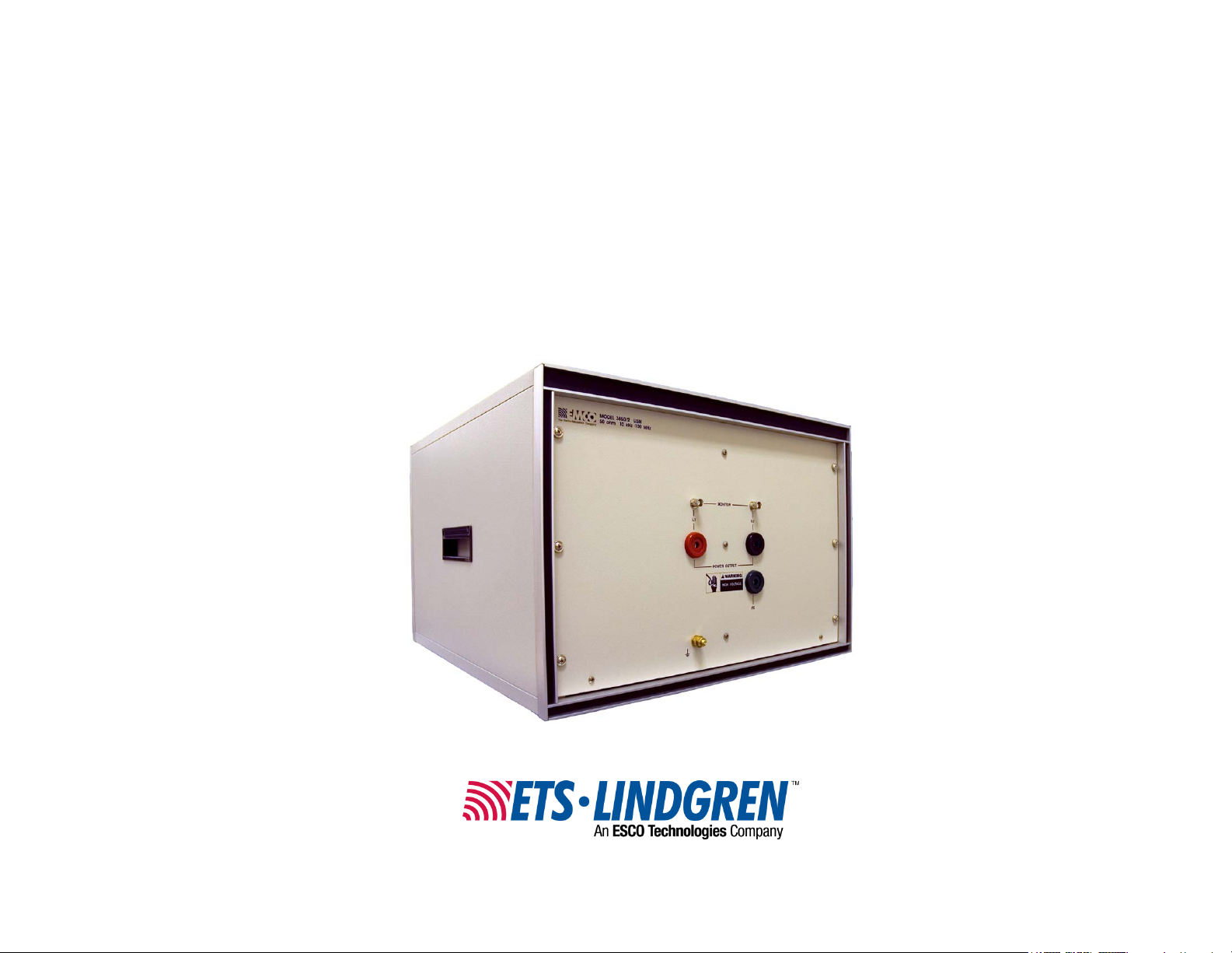
Model 3850/2
Line Impedance
Stabilization Network
(LISN)
User Manual
Page 2
ETS-Lindgren L.P. reserves the right to make changes to any product described
herein in order to improve function, design, or for any other reason. Nothing
contained herein shall constitute ETS-Lindgren L.P. assuming any liability
whatsoever arising out of the application or use of any product or circuit
described herein. ETS-Lindgren L.P. does not convey any license under its
patent rights or the rights of others.
© Copyright 1996–2009 by ETS-Lindgren L.P. All Rights Reserved. No part
of this document may be copied by any means without written permission
from ETS-Lindgren L.P.
Trademarks used in this document: The ETS-Lindgren logo is a trademark of
ETS-Lindgren L.P.
Revision Record | MANUAL 3850/2 | Part #399139, Rev. E
Revision Description Date
A–C Initial Release; updates December, 1996
D Rebrand October, 2008
E Added product photos February, 2009
ii |
Page 3

Table of Contents
Notes, Cautions, and Warnings ................................................ v
1.0 Introduction .......................................................................... 7
ETS-Lindgren Product Information Bulletin ................................................... 7
2.0 Maintenance ......................................................................... 9
Service Procedures ....................................................................................... 9
3.0 Specifications ..................................................................... 11
Electrical Specifications ............................................................................... 11
Physical Specifications ................................................................................ 11
4.0 Installation .......................................................................... 13
Power ........................................................................................................... 14
Equipment Under Test ................................................................................. 16
Spectrum Analyzer / Receiver ..................................................................... 17
Appendix A: Warranty ............................................................. 19
| iii
Page 4

This page intentionally left blank.
iv |
Page 5
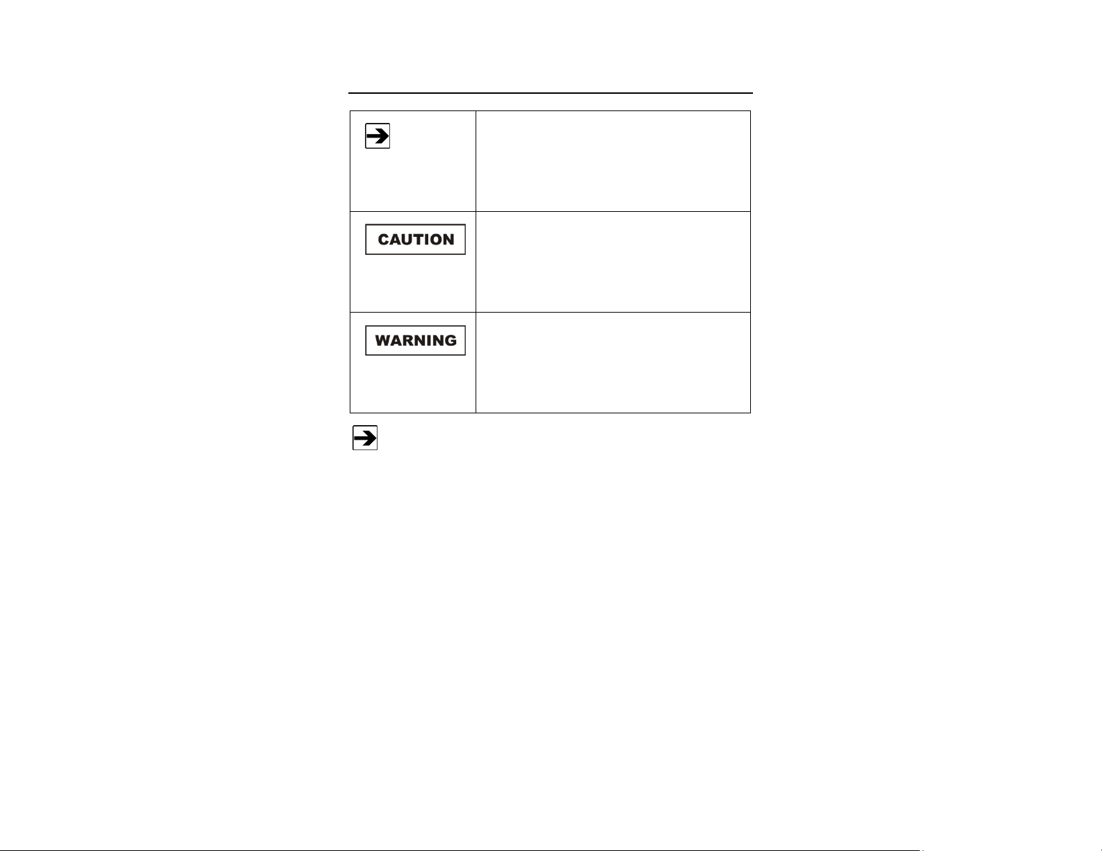
Notes, Cautions, and Warnings
Note: Denotes helpful information intended to
See the ETS-Lindgren Product Information Bulletin for safety,
regulatory, and other product marking information.
provide tips for better use of the product.
Caution: Denotes a hazard. Failure to follow
instructions could result in minor personal injury
and/or property damage. Included text gives proper
procedures.
Warning: Denotes a hazard. Failure to follow
instructions could result in SEVERE personal injury
and/or property damage. Included text gives proper
procedures.
| v
Page 6

This page intentionally left blank.
vi |
Page 7

1.0 Introduction
The ETS-Lindgren
Model 3850/2 Line
Impedance Stabilization
Network (LISN) is a
two-channel low pass filter
network used for
conducted emissions
measurement.
The Model 3850/2 is designed to isolate the equipment under test from an
external power source while steering any radio frequency signals from the power
line to a 50-ohm port. The conducted emissions measurements may be made in
accordance with regulatory compliance standards.
ETS-Lindgren Product Information Bulletin
See the ETS-Lindgren Product Information Bulletin included with your shipment
for the following:
• Warranty information
• Safety, regulatory, and other product marking information
• Steps to receive your shipment
• Steps to return a component for service
• ETS-Lindgren calibration service
• ETS-Lindgren contact information
Introduction | 7
Page 8

This page intentionally left blank.
8 | Introduction
Page 9

2.0 Maintenance
Before performing any maintenance, follow
the safety information in the ETS-Lindgren
Product Information Bulletin included with
your shipment.
Maintenance of the Model 3850/2 is limited
to external components such as cables or
connectors.
Clean the exterior of the cabinet using a
damp cloth and mild cleaner. Always
unplug the unit before cleaning.
To prevent electrical shock, do not remove
cover.
If you have any questions concerning
maintenance, contact ETS-Lindgren
Customer Service.
Service Procedures
For the steps to return a system or system component to ETS-Lindgren for
service, see the Product Information Bulletin included with your shipment.
Maintenance | 9
Page 10

This page intentionally left blank.
10 | Maintenance
Page 11

3.0 Specifications
Electrical Specifications
Frequency Range: 9 kHz – 100 MHz
(VDE 0876 specified curve ± 20%
Lines Plus Ground: 2
Network Inductance: 50 µH / 250 µH
Network Impedance: 50 Ω
Current Rating: 50 Amperes
Maximum AC Voltage: 250 VAC line-to-ground
440 VAC line-to-line
Input Connectors: 50 Amperes
Output Connectors: 50 Amperes
Monitor Port: BNC
1 per line
Environmental
Installation: Indoor use only
Altitude: 15000 ft (4572 m) max
Temperature: 0°C to 40°C (32°F to 104°F)
Relative Humidity: 80% up to 31°C (87.8°F)
decreasing linearly to 50% at
°C (104°F)
40
Physical Specifications
Height: 34.9 mm (13.7 in)
Width: 51.4 mm (20.2 in)
Depth: 57.1 mm (22.5 in)
Weight: 20.4 kg (44.97 lb)
Specifications | 11
Page 12

This page intentionally left blank.
12 | Specifications
Page 13

4.0 Installation
Before connecting any components, follow the
safety information in the ETS-Lindgren
Product Information Bulletin included with your
shipment.
Overcurrent protection is not provided in the
Model 3850/2. The unit must be connected to a
power mains with properly rated mains
protection.
The Model 3850/2 is provided with a protective
earthing connection. The unit should only be
connected to a mains source which utilizes a
protective earth conductor. Due to the high
leakage current to ground inherent in this type
of equipment, it is necessary to properly
connect the Model 3850/2 to an appropriate
earthing point on the power mains prior to
energizing. This earthing point should be
determined by an electrician authorized to
perform such work by appropriate code or law.
Any interruption of the protective conductor
inside or outside of the unit is likely to make the
Model 3850/2 dangerous. Intentional
interruption is prohibited.
The Model 3850/2 is provided with resistors to
help bleed off high voltage transients, but it is
advisable to connect the input and output
connectors to their proper power lines and
loads before connecting the monitor port to the
measurement instrumentation; otherwise,
power surges or transients can damage the test
instrumentation mixers or attenuators.
Installation | 13
Page 14

Power
Model 3850/2 Back Panel
• The Model 3850/2 Line Impedance Stabilization Network (LISN) is
nominally designed for a 50-ampere current capacity. Maximum
line-to-line voltage must not exceed the voltage rating of the power
connectors provided on the input and output of the unit. See
Specifications on page 11 for the applicable maximum value.
14 | Installation
Page 15

• The input power connection to
the line side of the Model 3850/2
is made through the red and
black pin receptacles labeled L1
and L2 on the back panel.
Power to the Model 3850/2
should be through a properly
rated circuit breaker and/or a
switch which can remove power
from the unit in case of
emergency. This device should
be installed near the
Model 3850/2.
• The green pin receptacle and
the brass lug terminal are both
connected to chassis ground.
Prior to energizing the
Model 3850/2, the earth
connection from the power
mains must be connected to the
green pin receptacle.
• The brass lug terminal should be bonded to the ground plane of the
conducted emissions test setup. This line does not provide high frequency
isolation and should not carry any voltage above earth potential.
Installation | 15
Page 16

Equipment Under Test
Model 3850/2 Front Panel
• The Equipment Under Test
(EUT) is connected to the
Model 3850/2 through the red
and black socket receptacles
located on the front panel.
• The ground connection to the
EUT is made through the green
socket receptacle.
• In normal operation, the radio
frequency bonding stud on the
front panel should be connected
to the ground plane of the
conducted emissions test setup
by a grounding strap or braid.
16 | Installation
Page 17

Spectrum Analyzer / Receiver
• Use the BNC connectors on the front panel to connect the spectrum
analyzer or EMI receiver. See page 16 for a view of the front panel
connectors.
• The monitor port which is not being monitored should be terminated
into a coaxial 50-ohm terminator.
Connect the input and output terminals to their proper mains
connections and EUT connections before connecting the monitor port
to the measurement instrumentation; otherwise, power surges may
damage the test instrumentation mixers or attenuators.
• Removal of a terminator and connection to the BNC receptacle will not
generate power surges.
• When the power is to be disconnected, remove the coaxial connection
to the measurement instrumentation first to avoid possible damage.
Installation | 17
Page 18

This page intentionally left blank.
18 | Installation
Page 19

Appendix A: Warranty
See the Product Information Bulletin included with your shipment for
the complete ETS-Lindgren warranty for your Model 3850/2 Line
Impedance Stabilization Network (LISN).
DURATION OF WARRANTIES FOR MODEL 3850/2
All product warranties, except the warranty of title, and all remedies for warranty
failures are limited to two years.
Product Warranted Duration of Warranty Period
Model 3850/2 Line Impedance
Stabilization Network (LISN)
2 Years
Warranty | 19
 Loading...