

Page 1
Model 3303
Rod Antenna
User Manual
Model 3303 Antenna Base
Page 2

ETS-Lindgren L.P. reserves the right to make changes to any product described
herein in order to improve function, design, or for any other reason. Nothing
contained herein shall constitute ETS-Lindgren L.P. assuming any liability
whatsoever arising out of the application or use of any product or circuit
described herein. ETS-Lindgren L.P. does not convey any license under its
patent rights or the rights of others.
© Copyright 1993–2011 by ETS-Lindgren L.P. All Rights Reserved. No part
of this document may be copied by any means without written permission
from ETS-Lindgren L.P.
Trademarks used in this document: The ETS-Lindgren logo is a trademark of
ETS-Lindgren L.P.
Revision Record | MANUAL 3303 | Part #399047, Rev. D
Revision Description Date
A Initial Release October, 1993
B Added Model 3305 Kit content October, 2002
C Rebrand September, 2010
D Updated monopole rod element
information
ii |
July, 2011
Page 3

Table of Contents
Notes, Cautions, and Warnings ............................................... iv
1.0 Introduction .......................................................................... 5
Standard Configuration .................................................................................. 6
Antenna Base ........................................................................................ 6
Counterpoise ......................................................................................... 6
Monopole Element ................................................................................. 6
Model 3305 E-Field Shielding Effectiveness Test Kit .................................... 8
Tripod Options ............................................................................................... 8
ETS-Lindgren Product Information Bulletin ................................................. 10
2.0 Maintenance ....................................................................... 11
Annual Calibration ....................................................................................... 11
Replacement and Optional Parts ................................................................. 12
Service Procedures ..................................................................................... 12
3.0 Specifications ..................................................................... 13
Electrical Specifications ............................................................................... 13
Physical Specifications ................................................................................ 13
4.0 Assembly, Mounting, and Operation ............................... 15
Assembly ..................................................................................................... 16
Attach Counterpoise ............................................................................ 16
Assemble / Attach Rod Element .......................................................... 17
Mounting ...................................................................................................... 18
4-TR Tripod .......................................................................................... 18
7-TR and Mast Mounting Options ........................................................ 18
2x2 Boom Mounting Options ............................................................... 19
Operation ..................................................................................................... 20
5.0 Model 3305 Suggested Test Setup ................................... 21
Measuring Electronic Field Shielding Effectiveness .................................... 21
Suggested Test Setup Diagram ................................................................... 22
Electric Field Shielding Effectiveness Measurement ................................... 24
6.0 Typical Data ........................................................................ 27
Appendix A: Warranty ............................................................. 29
| iii
Page 4
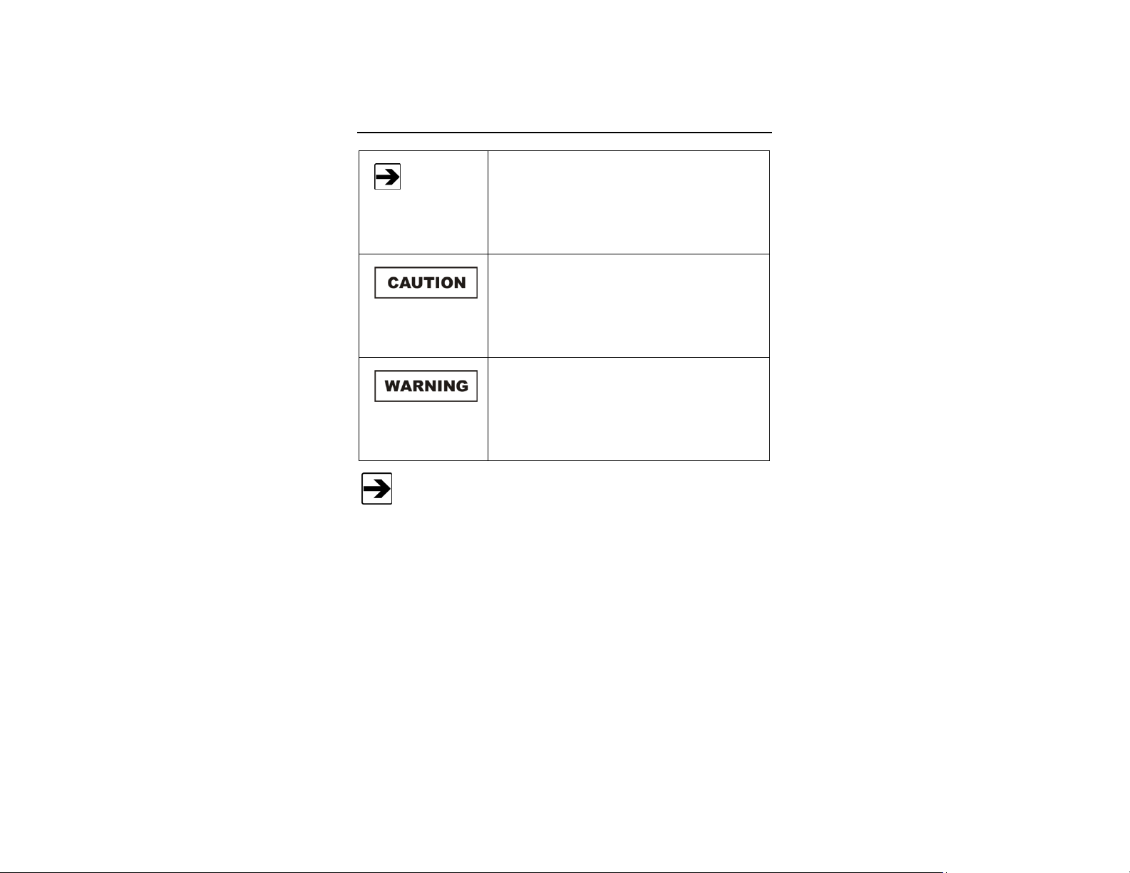
Notes, Cautions, and Warnings
Note: Denotes helpful information intended to
See the ETS-Lindgren Product Information Bulletin for safety,
regulatory, and other product marking information.
provide tips for better use of the product.
Caution: Denotes a hazard. Failure to follow
instructions could result in minor personal injury
and/or property damage. Included text gives proper
procedures.
Warning: Denotes a hazard. Failure to follow
instructions could result in SEVERE personal injury
and/or property damage. Included text gives proper
procedures.
iv |
Page 5
1.0 Introduction
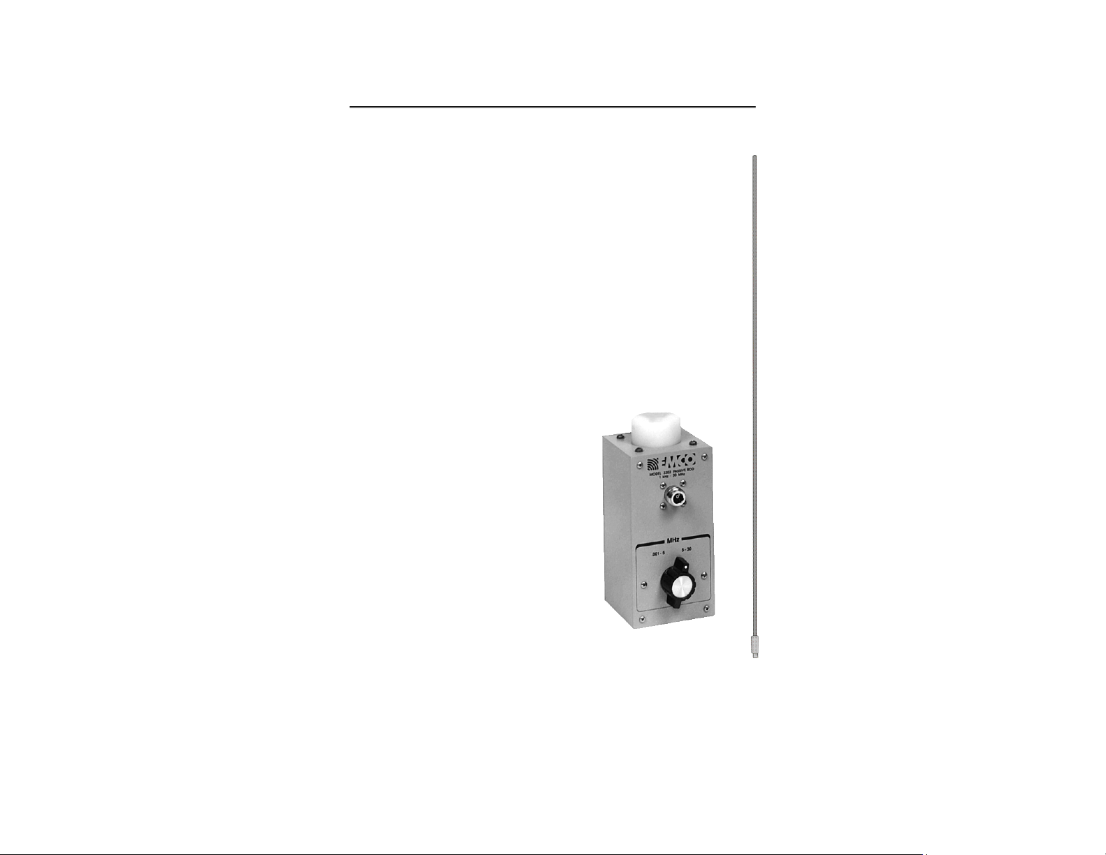
The ETS-Lindgren Model 3303 Rod Antenna is a passive broadband
electric field monopole transmitting antenna, and may also be used as a
passive receive antenna. The Model 3303 has a frequency range of
1 kHz to 30 MHz and features manual band switching between
0.001-5 MHz and 5-30 MHz. The maximum power handled by the
Model 3303 is 1 kW.
The base of the Model 3303 is constructed of aluminum, providing
strength and portability. The 1/4–20 threaded receptacle in the base is
compatible with ETS-Lindgren tripods and most others. The housing
contains the band-switching mechanism and a female Type N connector.
Each Model 3303 is individually calibrated
per (ESCM) or IEEE Std 291 using NIST
traceable equipment. Actual individual
calibration factors and a signed Certificate of
Calibration Conformance are included with
each antenna. By knowing the actual
antenna factors and performance
characteristics instead of typical data, you
can more accurately calculate the
field strength in your tests.
Model 3303 Antenna Base and
Introduction | 5
Monopole Element
Page 6
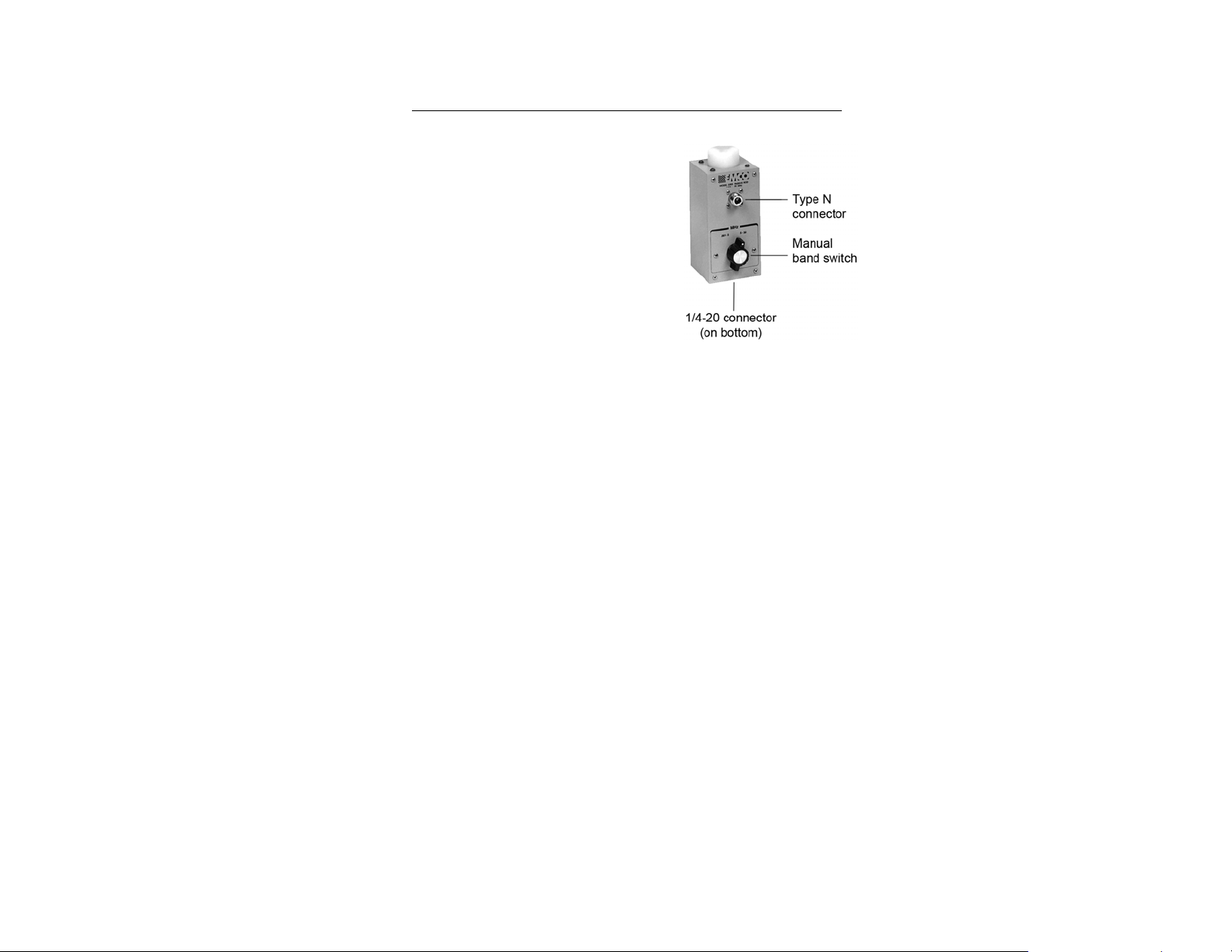
Standard Configuration
ANTENNA BASE
• Type N connector
• Built-in manual band switch
• Drilled to accept ETS-Lindgren or other tripod
mount with standard 1/4–20 threads
COUNTERPOISE
60 centimeters (not shown)
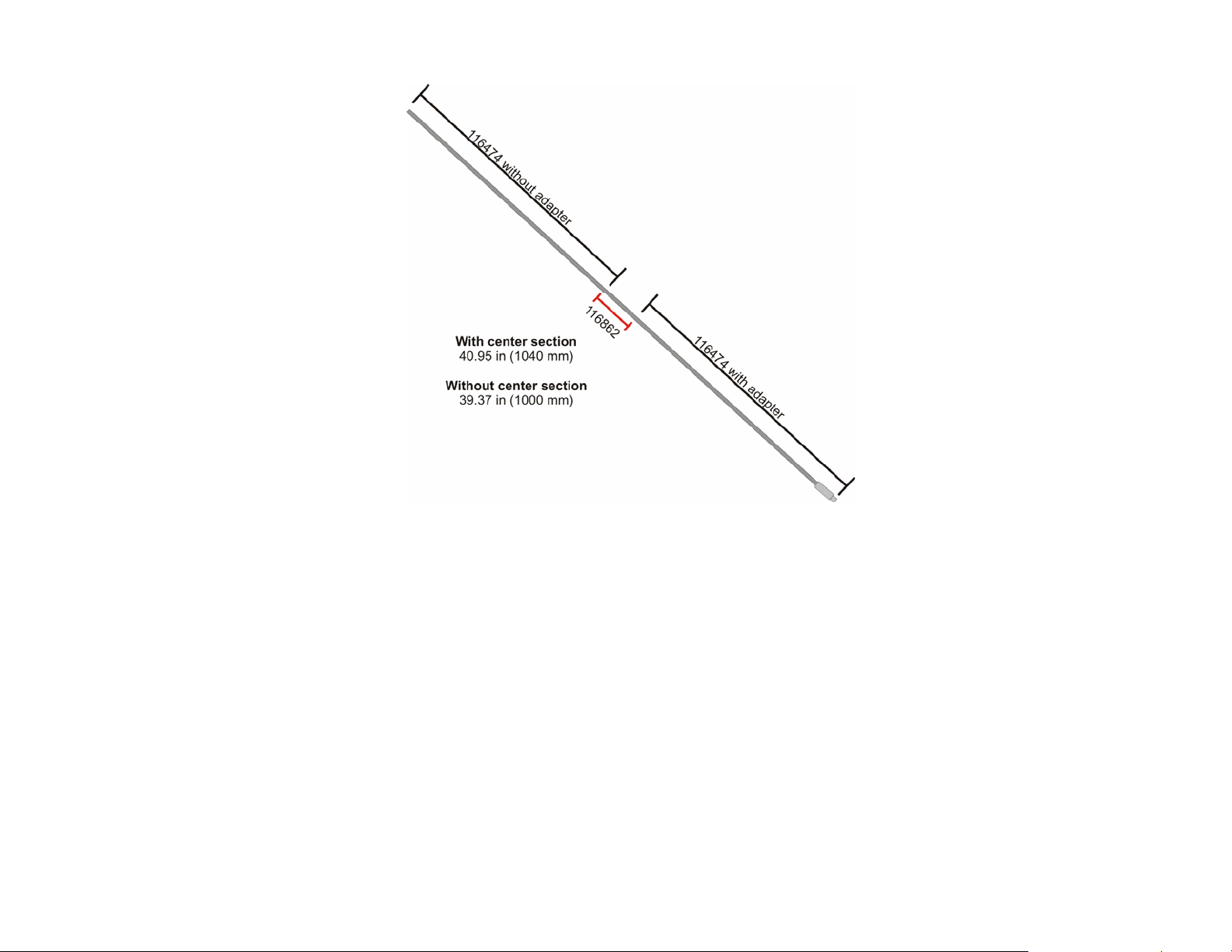
MONOPOLE ELEMENT
The monopole element includes these parts for assembly:
• (1) 116474 Rod section without antenna adapter
• (1) 116474 Rod section with antenna adapter
• (1) 116862 Center section
The monopole may be assembled as follows:
• For a finished length of 40.95 in (1040 mm)—Assemble all
parts, including the 116862 center section.
• For a finished length of 39.37 in (1000 mm)—Assemble all
parts except for the 116862 center section.
See page 17 for the steps to assemble the monopole.
6 | Introduction
Page 7
Introduction | 7
Page 8

Model 3305 E-Field Shielding Effectiveness Test Kit
The ETS-Lindgren Model 3305 E-Field Shielding Effectiveness Test Kit is a
set that includes these antennas:
• Model 3303
• Model 3301C Active Monopole Antenna
Together these antennas are designed to measure shielding effectiveness per
IEEE 299, MIL-STD-285, and NSA 65-6. The set operates from 1 kHz to 30 MHz.
The maximum power required to measure the attenuation per NSA 65-6 is
80 watts.
Additional information about the Model 3301C can be found at
www.ets-lindgren.com/3301C
Model 3303 and Model 3301C are also sold separately.
Tripod Options
.
ETS-Lindgren offers the following non-metallic, non-reflective tripods for use at
both indoor and outdoor EMC test sites.
8 | Introduction
Page 9
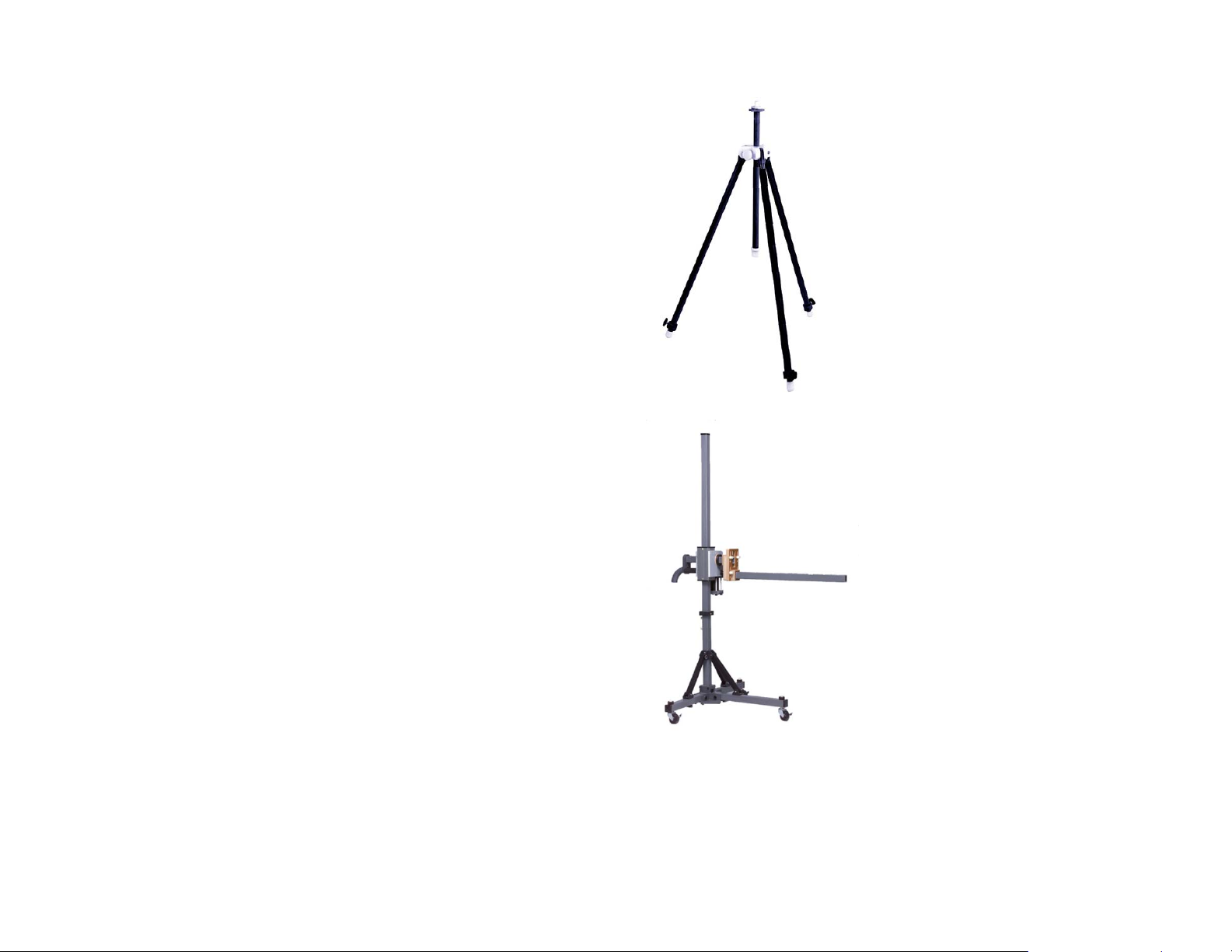
• 4-TR Tripod—Constructed of linen
phenolic and delrin, designed with an
adjustable center post for precise height
adjustments. Maximum height is 2.0 m
(80.0 in), and minimum height is 94 cm
(37.0 in). This tripod can support up to
an 11.8 kg (26.0 lb) load.
• 7-TR Tripod—Constructed of PVC and
fiberglass components, providing
increased stability for physically large
antennas. The unique design allows for
quick assembly, disassembly, and
convenient storage. Allows several
different configurations, including options
for manual or pneumatic polarization.
Quick height adjustment and locking
wheels provide ease of use during
testing. Maximum height is 2.17 m
(85.8 in), with a minimum height of 0.8 m
(31.8 in). This tripod can support a
13.5 kg (30 lb) load.
Introduction | 9
Page 10

ETS-Lindgren Product Information Bulletin
See the ETS-Lindgren Product Information Bulletin included with your shipment
for the following:
• Warranty information
• Safety, regulatory, and other product marking information
• Steps to receive your shipment
• Steps to return a component for service
• ETS-Lindgren calibration service
• ETS-Lindgren contact information
10 | Introduction
Page 11

2.0 Maintenance
Before performing any maintenance,
follow the safety information in the
ETS-Lindgren Product Information
Bulletin included with your shipment.
WARRANTY
Maintenance of the Model 3303 is limited
external components such as cables or
connectors.
Clean the exterior of the cabinet using a
damp cloth and mild cleaner. Always
unplug the unit before cleaning.
If you have any questions concerning
maintenance, contact ETS-Lindgren
Customer Service.
Annual Calibration
See the Product Information Bulletin included with your shipment for information
on ETS-Lindgren calibration services.
Maintenance | 11
Page 12

Replacement and Optional Parts
Following are the part numbers for ordering replacement or optional parts for the
Model 3303 Rod Antenna.
Part Description Part Number
Counterpoise (60 cm) 100692C
• 116476 Monopole,
entire assembly
Monopole Element
Note: 116474 Rod section with antenna adapter is not a replaceable part; if
you need that section, you will need to order the entire monopole assembly,
116476.
• 116474 Rod section without
antenna adapter
• 116862 Center section
Service Procedures
For the steps to return a system or system component to ETS-Lindgren for
service, see the Product Information Bulletin included with your shipment.
12 | Maintenance
Page 13

3.0 Specifications
Electrical Specifications
Frequency: 1 kHz—30 MHz
Maximum Continuous
Power:
Peak Power: 1 kW
Impedance (Nominal): Varies with frequency
Connector: Type N female
300 W
Note: Calibrated in a 50-ohm system.
Physical Specifications
Base Height: 15.2 cm (6.0 in)
Width: 7.6 cm (3.0 in)
Depth: 7.6 cm (3.0 in)
Monopole Element:
• For a finished length of 40.95 in
(1040 mm)—Assemble (2) 116474 rod
sections and (1) 116862.
• For a finished length of 39.37 in
(1000 mm)—Assemble (2) 116474 rod
sections. Do not use the 116862 center
section.
Weight: 1.3 kg (2.8 lb)
Specifications | 13
See page 17 for the steps to assemble the
monopole.
Page 14

This page intentionally left blank.
14 | Specifications
Page 15

4.0 Assembly, Mounting, and Operation
Before connecting any components, follow the
safety information in the ETS-Lindgren
Product Information Bulletin included with your
shipment.
Antennas are precision measurement devices.
Handle your antenna with care.
Do not cross thread any connections or permanent damage to the
antenna could occur.
The 1/4–20 mount on the bottom of the Model 3303 is not a
ground location.
Assembly, Mounting, and Operation | 15
Page 16

Assembly
ATTACH COUNTERPOISE
Do not lift the Model 3303 by the counterpoise.
The counterpoise attaches on the top of the
Model 3303 Rod Antenna base with the rod
element passing through the opening in the
counterpoise. Mounting the counterpoise
between the housing and the rod antenna
prevents the body of the antenna from
intruding into the field being measured.
1. Unfold the counterpoise and place it on top of the base.
2. Attach the counterpoise to the base using the four screws on the top of
the base.
16 | Assembly, Mounting, and Operation
Page 17

ASSEMBLE / ATTACH ROD ELEMENT
1. Assemble the rod element:
• For a finished length of 40.95 in (1040 mm)—Assemble (2) 116474
rod sections and (1) 116862 center section.
• For a finished length of 39.37 in (1000 mm)—Assemble (2) 116474
rod sections. Do not use the 116862 center section.
2. Attach the rod to the
element connector, passing
it through the hole in the
counterpoise.
Assembly, Mounting, and Operation | 17
Page 18

Mounting
4-TR TRIPOD
Use the 1/4–20 mount on the bottom of the Model 3303 to mount directly onto an
ETS-Lindgren 4-TR Tripod; no additional hardware is required.
7-TR AND MAST MOUNTING OPTIONS
Following are options for mounting the
Model 3303 onto an ETS-Lindgren 7-TR
Tripod or mast. Contact the ETS-Lindgren
Sales Department for information on
ordering optional mounting hardware.
Mast refers to 2070 Series, 2075, and
2175 Antenna Towers. 7-TR refers to
109042, 108983, and 108507 booms:
• 109042 boom—Straight boom; for
general antenna mounting on a 7-TR
• 108983 boom—Offset boom; for general
antenna mounting on a 7-TR with
pneumatic or manual polarization; can
also be used to mount stinger-type
antennas
• 108507 boom—For Model 3106 Series
antennas only; when changing
polarization, maintains centerline
rotation
18 | Assembly, Mounting, and Operation
Page 19

2X2 BOOM MOUNTING OPTIONS
2x2 boom refers to a typical 2-inch by 2-inch boom.
Following are options for mounting the Model 3303 onto a 2x2 boom. Contact the
ETS-Lindgren Sales Department for information on ordering optional mounting
hardware.
Assembly, Mounting, and Operation | 19
Page 20

Operation
Reduce amplifier power to zero watts before
band switching the Model 3303.
Select the desired frequency band by
rotating the band switch.
20 | Assembly, Mounting, and Operation
Page 21

5.0 Model 3305 Suggested Test Setup
Before connecting any components, follow the
safety information in the ETS-Lindgren
Product Information Bulletin included with your
shipment.
Measuring Electronic Field Shielding Effectiveness
Reduce amplifier power to zero watts before
band switching the Model 3303.
Reference:
• NSA 65-6
• MIL-STD-285
1. Place the transmitting and receiving antennas so that they are
24 inches plus the thickness of the screen room wall apart from each
other.
2. Set up equipment as shown in Suggested Test Setup Diagram on
page 22.
3. Turn generator to ON position.
Disable RF output of generator.
Turn amplifier to ON position.
Turn receiver to ON position.
Turn Model 3301C power on.
Set receiver.
Set the attenuator at maximum (100 dB–150 dB) attenuation.
Enable RF output of the generator.
4. Adjust signal amplitude on signal generator to maximum allowed by
amplifier input.
Model 3305 Suggested Test Setup | 21
Page 22

5. Establish a reference level by decreasing the attenuation level until the
signal can be detected by the receiver. Note the attenuator setting.
6. Relocate antennas so that the screen room wall is between them.
7. Reduce attenuation further until signal is again seen at the same level
as without shielding.
The difference in the two attenuator settings is the shielding effectiveness. If the
signal cannot be seen with a zero setting, then the shielding effectiveness is
greater than the attenuation range or the power amplifier does not have enough
power. Suggested Test Setup Diagram on page 22.
The table on page 24 shows the maximum shielding effectiveness measuring
capability of the Model 3305 E-Field Shielding Effectiveness Test Kit and the
approximate wattage required for the Model 3303 Rod Antenna to meet the
minimum shielding requirements of NSA 65-6.
These shielding effectiveness readings are valid only if the power
amplifier is operating in the linear region. This can be verified by
reducing (or increasing) attenuation and observing the receiver signal
on the analyzer or receiver. If the receiving signal also decreases (or
increases) by the same amount then the amplifier is operating in the
linear region.
Suggested Test Setup Diagram
See next page for diagram.
22 | Model 3305 Suggested Test Setup
Page 23

Model 3305 Suggested Test Setup | 23
Page 24

Electric Field Shielding Effectiveness Measurement
Frequency NSA 65-6
Minimum
Attenuation for
Electric Field
Band 1
1 kHz 70 dB 80 Watts 100 dB
10 kHz 100 dB 80 Watts 120 dB
20 kHz 100 dB 80 Watts 115 dB
30 kHz 100 dB 70 Watts 110 dB
40 kHz 100 dB 75 Watts 112 dB
50 kHz 100 dB 40 Watts 110 dB
60 kHz 100 dB 35 Watts 110 dB
70 kHz 100 dB 40 Watts 110 dB
80 kHz 100 dB 25 Watts 110 dB
90 kHz 100 dB 30 Watts 110 dB
Approximate
Wattage
Required to
Meet NSA 65-6
Attenuation
Specifications
Maximum
Shielding
(Electric Field)
That Can be
Measured With
This Setup
100 kHz 100 dB 30 Watts 110 dB
200 kHz 100 dB 25 Watts 117 dB
300 kHz 100 dB 25 Watts 120 dB
400 kHz 100 dB 25 Watts 125 dB
500 kHz 100 dB 25 Watts 125 dB
600 kHz 100 dB 30 Watts 125 dB
700 kHz 100 dB 30 Watts 125 dB
800 kHz 100 dB 30 Watts 125 dB
900 kHz 100 dB 30 Watts 125 dB
24 | Model 3305 Suggested Test Setup
Page 25

Frequency NSA 65-6
Minimum
Attenuation for
Electric Field
Band 1, continued
1 MHz 100 dB 30 Watts 125 dB
2 MHz 100 dB 30 Watts 125 dB
4 MHz 100 dB 30 Watts 125 dB
5 MHz 100 dB 30 Watts 125 dB
Approximate
Wattage
Required to
Meet NSA 65-6
Attenuation
Specifications
Maximum
Shielding
(Electric Field)
That Can be
Measured With
This Setup
Frequency NSA 65-6
Minimum
Attenuation for
Electric Field
Band 2
5 MHz 100 dB 25 Watts 125 dB
6 MHz 100 dB 25 Watts 125 dB
8 MHz 100 dB 25 Watts 125 dB
10 MHz 100 dB 20 Watts 125 dB
15 MHz 100 dB 25 Watts 125 dB
20 MHz 100 dB 20 Watts 125 dB
25 MHz 100 dB 45 Watts 125 dB
30 MHz 100 dB 25 Watts 125 dB
Approximate
Wattage
Required to
Meet NSA 65-6
Attenuation
Specifications
Maximum
Shielding
(Electric Field)
That Can be
Measured With
This Setup
Model 3305 Suggested Test Setup | 25
Page 26

This page intentionally left blank.
26 | Model 3305 Suggested Test Setup
Page 27

6.0 Typical Data
Typical Data | 27
Page 28

This page intentionally left blank.
28 | Typical Data
Page 29

Appendix A: Warranty
See the Product Information Bulletin included with your shipment for
the complete ETS-Lindgren warranty for your Model 3303 Rod
Antenna.
DURATION OF WARRANTIES FOR MODEL 3303
All product warranties, except the warranty of title, and all remedies for warranty
failures are limited to two years.
Product Warranted Duration of Warranty Period
Model 3303 Rod Antenna 2 Years
Warranty | 29
 Loading...