

Page 1

Model 3181 / Model 3183 / Model 3184
End Fed
Mini-Bicon Antenna
User Manual
Model 3181 / Model 3184
Model 3183
Page 2

ETS-Lindgren L.P. reserves the right to make changes to any product described
herein in order to improve function, design, or for any other reason. Nothing
contained herein shall constitute ETS-Lindgren L.P. assuming any liability
whatsoever arising out of the application or use of any product or circuit
described herein. ETS-Lindgren L.P. does not convey any license under its
patent rights or the rights of others.
© Copyright 2009–2010 by ETS-Lindgren L.P. All Rights Reserved. No part of
this document may be copied by any means without written permission from
ETS-Lindgren L.P.
Trademarks used in this document: The ETS-Lindgren logo is a trademark of
ETS-Lindgren L.P.
Revision Record
MANUAL,3181 3183 3184 MINI-BICON ANTENNA | Part #399821, Rev. D
Revision Description Date
A Initial Release October, 2009
B Updated data charts in
Typical Data; updated
Mounting Instructions
C Updated 3183 illustrations; added
note about 3183 stem; updated
Physical Specifications
D Updated 3183 photos; updated
3183 data
November, 2009
February, 2010
March, 2010
ii |
Page 3

Table of Contents
Notes, Cautions, and Warnings .............................................. vii
1.0 Introduction .......................................................................... 9
Model 3181 / Model 3184 .............................................................................. 9
Model 3183 .................................................................................................... 9
Tripod Options ............................................................................................. 10
ETS-Lindgren Product Information Bulletin ................................................. 11
2.0 Maintenance ....................................................................... 13
Annual Calibration ....................................................................................... 13
Replacement and Optional Parts ................................................................. 13
Service Procedures ..................................................................................... 14
3.0 Specifications ..................................................................... 15
Electrical Specifications ............................................................................... 15
Physical Specifications ................................................................................ 15
4.0 Mounting Instructions ....................................................... 17
Using the Antenna Mount Assembly on a 4-TR ........................................... 18
Step 1: Attach Antenna Mount Assembly to 4-TR ............................... 19
Step 2: Mount Antenna to Antenna Mount Assembly .......................... 21
Step 3: Orient to Notch (Model 3183 Only) ......................................... 22
Additional Mounting Options ........................................................................ 23
7-TR and Mast Mounting Options ........................................................ 23
2x2 Boom Mounting Options ............................................................... 25
Weatherizing Kit for Outdoor Testing (3181/3184 Only) .............................. 26
Step 1: Wrap Moldable Plastic Seal Tape ........................................... 27
Step 2: Mold Plastic Seal Tape............................................................ 28
Step 3: Wrap Heavy-Duty All-Weather Vinyl Tape .............................. 28
5.0 Typical Data ........................................................................ 29
Model 3181 .................................................................................................. 29
3181 Antenna Factor / Gain................................................................. 29
3181 VSWR ......................................................................................... 30
Model 3183 .................................................................................................. 31
3183 Antenna Factor / Gain................................................................. 31
3183 VSWR ......................................................................................... 32
| iii
Page 4

Model 3184 .................................................................................................. 33
3184 Antenna Factor / Gain................................................................. 33
3184 VSWR ......................................................................................... 34
Typical E-Plane Patterns—Model 3181 ....................................................... 35
3181 E-Plane at 500 MHz—1 GHz ...................................................... 35
3181 E-Plane at 2 GHz –5 GHz........................................................... 36
3181 E-Plane at 6 GHz–9 GHz............................................................ 37
3181 E-Plane at 10 GHz–13 GHz........................................................ 38
3181 E-Plane at 14 GHz–18 GHz........................................................ 39
Typical E-Plane Patterns—Model 3183 ....................................................... 40
3183 E-Plane at 1 GHz ........................................................................ 40
3183 E-Plane at 2 GHz ........................................................................ 41
3183 E-Plane at 3 GHz ........................................................................ 42
3183 E-Plane at 4 GHz ........................................................................ 43
3183 E-Plane at 5 GHz ........................................................................ 44
3183 E-Plane at 6 GHz ........................................................................ 45
3183 E-Plane at 7 GHz ........................................................................ 46
3183 E-Plane at 8 GHz ........................................................................ 47
3183 E-Plane at 9 GHz ........................................................................ 48
3183 E-Plane at 10 GHz ...................................................................... 49
3183 E-Plane at 11 GHz ...................................................................... 50
3183 E-Plane at 12 GHz ...................................................................... 51
3183 E-Plane at 13 GHz ...................................................................... 52
3183 E-Plane at 14 GHz ...................................................................... 53
3183 E-Plane at 15 GHz ...................................................................... 54
3183 E-Plane at 16 GHz ...................................................................... 55
3183 E-Plane at 17 GHz ...................................................................... 56
3183 E-Plane at 18 GHz ...................................................................... 57
Typical H-Plane Patterns—Model 3183 ....................................................... 58
3183 H-Plane at 1 GHz........................................................................ 58
3183 H-Plane at 2 GHz–18 GHz ......................................................... 59
Typical E-Plane Patterns—Model 3184 ....................................................... 60
3184 E-Plane at 2 GHz–3 GHz............................................................ 60
3184 E-Plane at 4 GHz–5 GHz............................................................ 61
3184 E-Plane at 6 GHz–7 GHz............................................................ 62
3184 E-Plane at 8 GHz–9 GHz............................................................ 63
iv |
Page 5

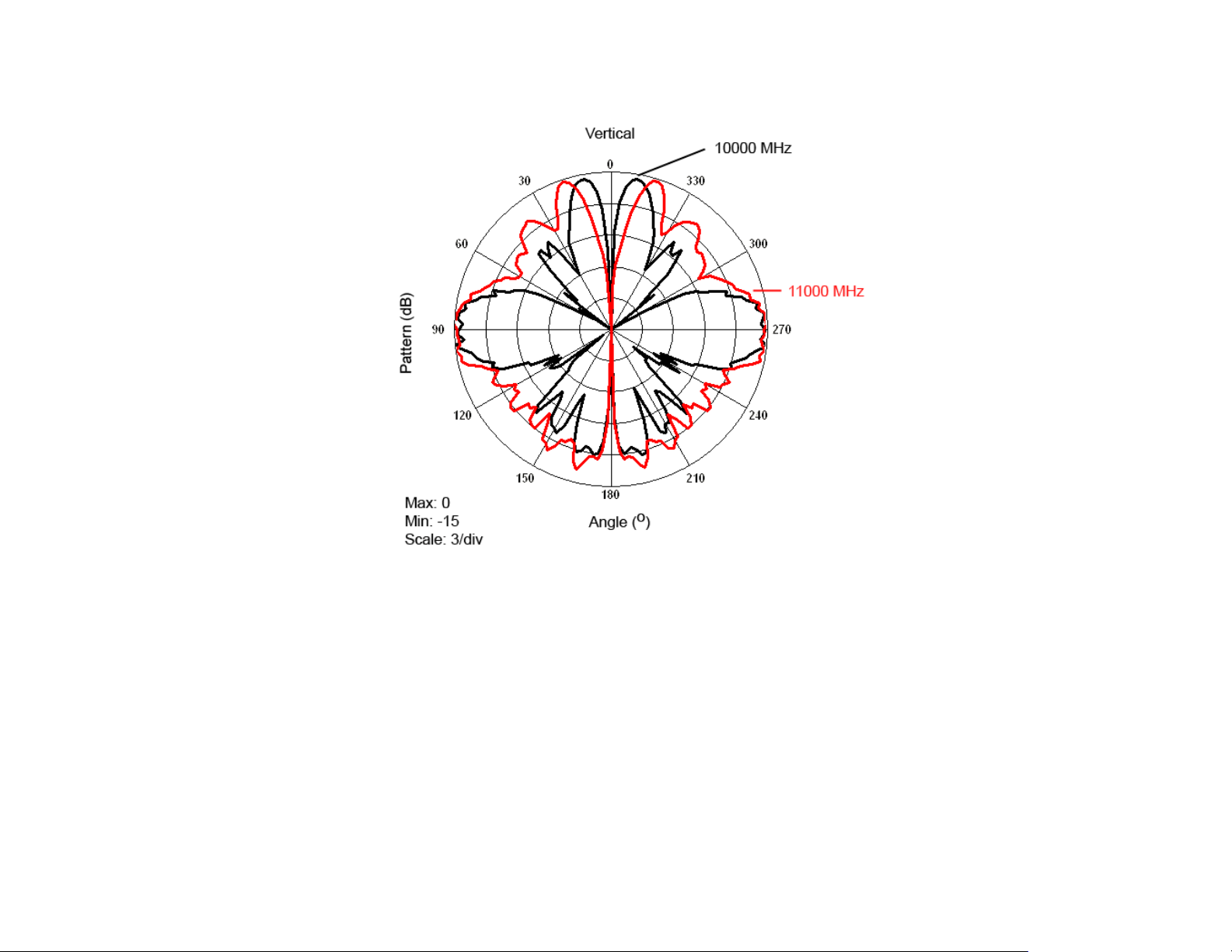
3184 E-Plane at 10 GHz–11 GHz........................................................ 64
3184 E-Plane at 12 GHz–13 GHz........................................................ 65
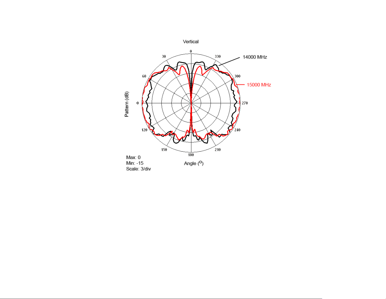
3184 E-Plane at 14 GHz–15 GHz........................................................ 66
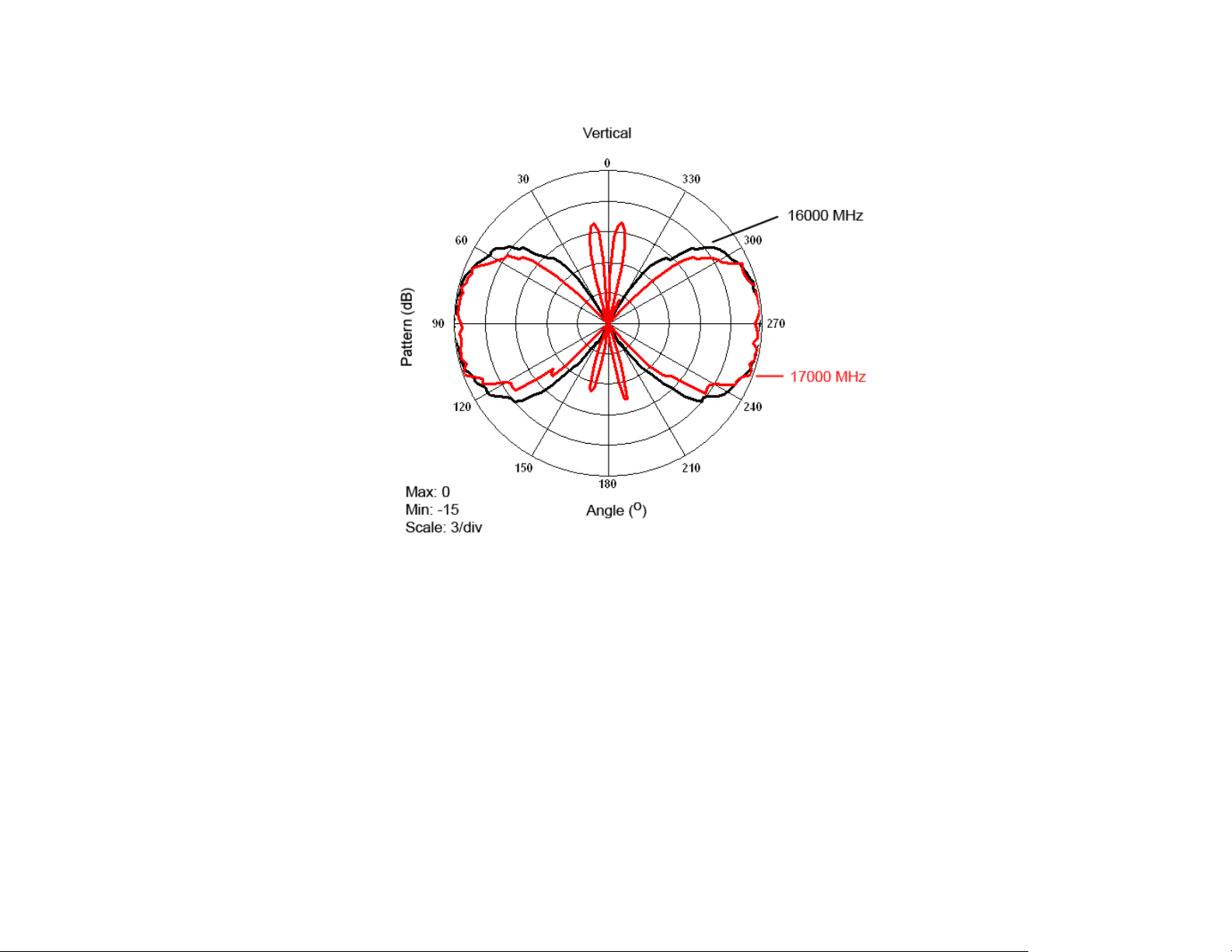
3184 E-Plane at 16 GHz–17 GHz........................................................ 67
3184 E-Plane at 18 GHz ...................................................................... 68
Typical H-Plane Patterns—Model 3184 ....................................................... 69
3184 H-Plane at 1 GHz........................................................................ 69
3184 H-Plane at 2 GHz–18 GHz ......................................................... 70
Appendix A: Warranty ............................................................. 71
| v
Page 6

This page intentionally left blank.
vi |
Page 7

Notes, Cautions, and Warnings
Note: Denotes helpful information intended to
See the ETS-Lindgren Product Information Bulletin for safety,
regulatory, and other product marking information.
provide tips for better use of the product.
Caution: Denotes a hazard. Failure to follow
instructions could result in minor personal injury
and/or property damage. Included text gives proper
procedures.
Warning: Denotes a hazard. Failure to follow
instructions could result in SEVERE personal injury
and/or property damage. Included text gives proper
procedures.
| vii
Page 8

This page intentionally left blank.
viii |
Page 9

1.0 Introduction
The ETS-Lindgren End Fed Mini-Bicons includes these two groups of
broadband omni-directional antennas:
Model 3181 / Model 3184
The Model 3181/3184 is designed for
surveillance, spectrum monitoring, and
shielding tests.
The frequency range for the Model 3181 is
500 MHz to 9 GHz and the frequency range
for the Model 3184 is 1 GHz to 18 GHz.
The Model 3181 performs best up to
9 GHz, but is usable to 18 GHz if
amplification is used. The Model 3184
performs better than the Model 3181 in the
9 GHz to 18 GHz range. Data to 18 GHz is
provided for both antennas.
The radome provides weather protection for
outdoor testing, and a weatherizing kit is
included to protect the antenna connection.
Model 3183
The Model 3183 is designed for
CISPR 16-1-4 chamber validation testing
above 1 GHz. The frequency range for the
Model 3183 is 1 GHz to 18 GHz.
The Model 3183 is not weather protected,
and is not recommended for outdoor
testing.
Never attempt to remove the stem from the Model 3183.
Introduction | 9
Page 10

The radiation pattern is omni-directional in the H-plane, allowing the antenna to
receive signals from every direction around the axis. The range covers most
wireless bands worldwide, and is designed for the lowest possible VSWR across
the range of operation. The antenna exhibits better than 2:1 VSWR for most of
the range, and never exceeds 5:1 above 1 GHz.
The small sizes of the antennas enable them to be used for amplifier harmonic
measurements when performing tests per IEC 61000-4-3.
Each antenna is calibrated during manufacturing. The results of the calibration
are tabulated as gain and antenna factor vs. frequency for use in Specification
Compliance Testing. Typical data is provided starting on page 29.
The Model 3181/3183/3184 includes a stinger mount and ships with an antenna
mount assembly for a variety of mounting configurations. For information on the
4-TR, see the next section, Tripod Options; for mounting information, see
Mounting Instructions on page 17.
Tripod Options
ETS-Lindgren offers the 4-TR
non-metallic, non-reflective tripod for use
at both indoor and outdoor EMC test
sites.
• Constructed of linen phenolic and
delrin, designed with an adjustable
center post for precise height
adjustments.
• Maximum height is 2.0 m (80.0 in),
and minimum height is 94 cm
(37.0 in).
• Can support up to an 11.8 kg (26.0 lb)
load.
10 | Introduction
Page 11

ETS-Lindgren Product Information Bulletin
See the ETS-Lindgren Product Information Bulletin included with your shipment
for the following:
• Warranty information
• Safety, regulatory, and other product marking information
• Steps to receive your shipment
• Steps to return a component for service
• ETS-Lindgren calibration service
• ETS-Lindgren contact information
Introduction | 11
Page 12

This page intentionally left blank.
12 | Introduction
Page 13

2.0 Maintenance
Before performing any maintenance, follow
the safety information in the ETS-Lindgren
Product Information Bulletin included with
your shipment.
WARRAN TY
Maintenance of the Model 3181/3183/3184
is limited to external components such as
cables or connectors.
If you have any questions concerning
maintenance, contact ETS-Lindgren
Customer Service.
Annual Calibration
See the Product Information Bulletin included with your shipment for information
on ETS-Lindgren calibration services.
Replacement and Optional Parts
Following are the part numbers for ordering replacement or optional parts for the
Model 3181/3183/3184 End Fed Mini--Bicon Antennas.
Part Description Part Number
Assembly, Antenna Mount 113956
The 114669 Spacer is included in the 113956 Antenna Mount
Assembly, but may also be ordered separately.
Spacer, Extension, Antenna Mount 114669
Moldable Plastic Seal Tape 920381
Heavy-duty All-weather Vinyl Tape 920382
Maintenance | 13
Page 14

Service Procedures
For the steps to return a system or system component to ETS-Lindgren for
service, see the Product Information Bulletin included with your shipment.
14 | Maintenance
Page 15

3.0 Specifications
Electrical Specifications
Frequency Range:
VSWR Ratio (Average): 2:1
Maximum Continuous Power: 100 W @ 500 MHz
Impedance: 50 Ω
Connector: SMA female
• 3181: 500 MHz–9 GHz
• 3183: 1 GHz–18 GHz
• 3184: 1 GHz–18 GHz
50 W @ 1 GHz
25 W @ 18 GHz
Physical Specifications
Length:
Width:
• 3181/3184: 38.35 cm (15.1 in)
• 3183: 37.3 cm (14.67 in)
• 3181/3184: 15.25 cm (6.0 in)
• 3183: 7.0 cm (2.76 in)
Stinger Length:
Weight:
• 3181/3183/3184:
16.0 cm (6.32 in)
• 3181: 1.03 kg (2.28 lb)
• 3183: 0.5 kg (1.1 lb)
• 3184: 0.65 kg (1.43 lb)
Specifications | 15
Page 16

This page intentionally left blank.
16 | Specifications
Page 17

4.0 Mounting Instructions
Before connecting any components, follow the
safety information in the ETS-Lindgren
Product Information Bulletin included with your
shipment.
The Model 3181/3183/3184 antennas are
precision measurement devices. Handle your
antenna with care.
Mounting Instructions | 17
Page 18

Using the Antenna Mount Assembly on a 4-TR
The antenna mount assembly ships with this
larger knob in place of the thumbscrew shown
in the following photos. The larger knob
provides the same functionality but provides
increased usability.
Each Model 3181/3183/3184 End Fed Mini-Bicon Antenna ships with an antenna
mount assembly for a variety of mounting configurations. To use the antenna
mount assembly with an ETS-Lindgren 4-TR Tripod, select the antenna mounting
orientation, attach the antenna mount assembly to the 4-TR, and then attach the
antenna to the antenna mount assembly. Each step is detailed in the following
sections.
18 | Mounting Instructions
Page 19

STEP 1: ATTACH ANTENNA MOUNT ASSEMBLY TO 4-TR
You may use the antenna mount assembly to mount the Model 3181/3183/3184
in vertical or horizontal orientation.
• Vertical orientation:
Attach the extension to
the threaded insert on
the bottom of the
mount and rotate to
tighten into place.
Attach the extension
to the 4-TR using the
threaded insert on the
bottom of the
extension. Turn the
extension to secure
the antenna mount
assembly to the 4-TR.
• Horizontal
orientation: You may
attach the antenna
mount assembly
directly to the 4-TR, or
you may use the
extension to attach it
to the 4-TR.
Mounting Instructions | 19
Page 20

To direct mount, attach the mount to the 4-TR using the threaded insert on the
side of the mount. Rotate to tighten into place.
To use the extension, attach the extension to the mount using the threaded
insert on the side of the mount, and then turn the extension to tighten. Attach the
extension to the 4-TR using the threaded insert on the bottom of the extension.
Rotate to tighten into place.
20 | Mounting Instructions
Page 21

STEP 2: MOUNT ANTENNA TO ANTENNA MOUNT ASSEMBLY
• Turn the
thumbscrew/knob to
loosen it.
• Insert the antenna
stinger into and
through the clamping
aperture.
• Turn the
thumbscrew/knob to
tighten it and secure
the antenna in place.
Vertical Mount
Horizontal Mount
Mounting Instructions | 21
Page 22

STEP 3: ORIENT TO NOTCH (MODEL 3183 ONLY)
• For consistency and
reduced uncertainty, use
the notch on the antenna
shaft to orient the
Model 3183. This ensures
that the same part of the
Model 3183 will face the
receive antenna during the
sVSWR test.
22 | Mounting Instructions
Page 23

Additional Mounting Options
7-TR AND MAST MOUNTING OPTIONS
To mount the Model
3181/3183/3184
vertically to a 7-TR or
mast using the antenna
mount assembly, you
must place the 114669
spacer over the
extension.
Following are options for mounting the Model 3181/3183/3184 onto an
ETS-Lindgren 7-TR Tripod or mast. See Using the Antenna Mount Assembly on
a 4-TR on page 18 for additional mounting and assembly information.
Contact the ETS-Lindgren Sales Department for information on ordering optional
mounting hardware.
Mounting Instructions | 23
Page 24
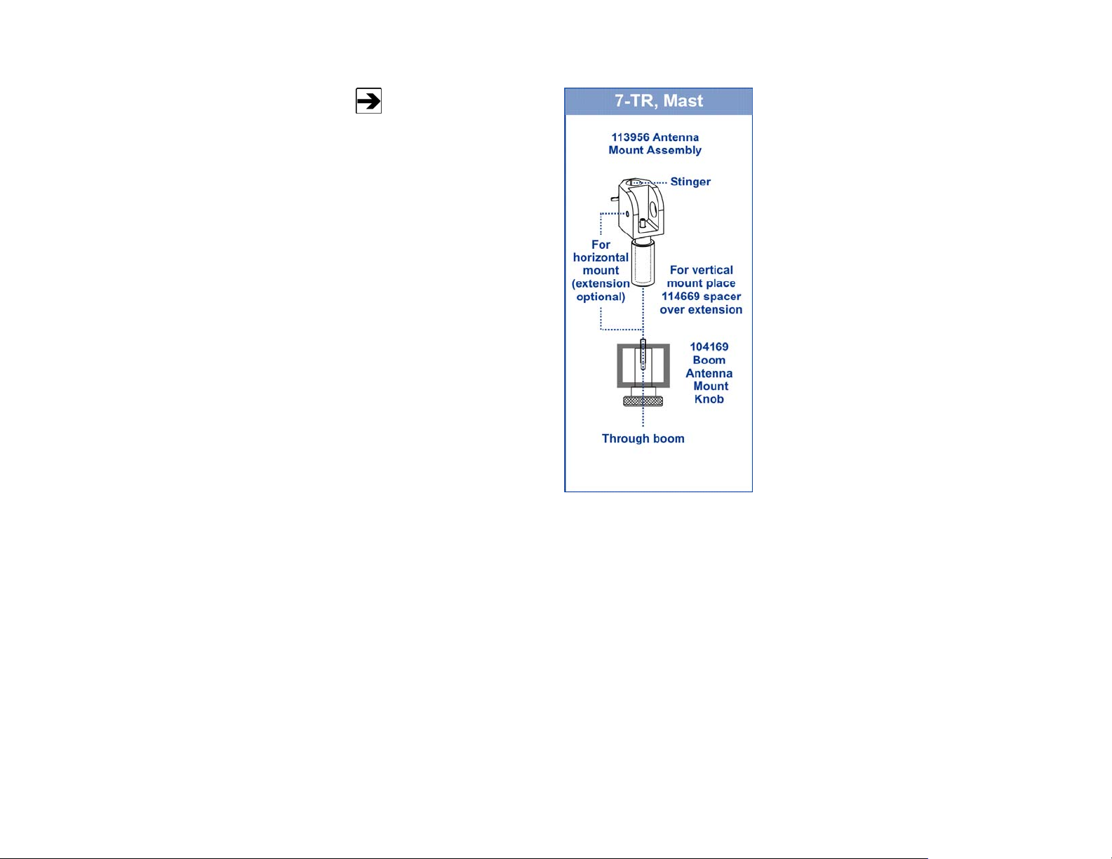
Mast refers to 2070 Series,
2075, and 2175 Antenna
Towers. 7-TR refers to
109042, 106328, and
108197 booms:
• 109042 boom—Straight
boom; for general
antenna mounting on a
7-TR
• 106328 boom—Offset
boom; for general
antenna mounting on a
7-TR with pneumatic or
manual polarization
• 108197 boom—Center
rotate boom; for
rear-mount stinger-type
antennas only
24 | Mounting Instructions
Page 25
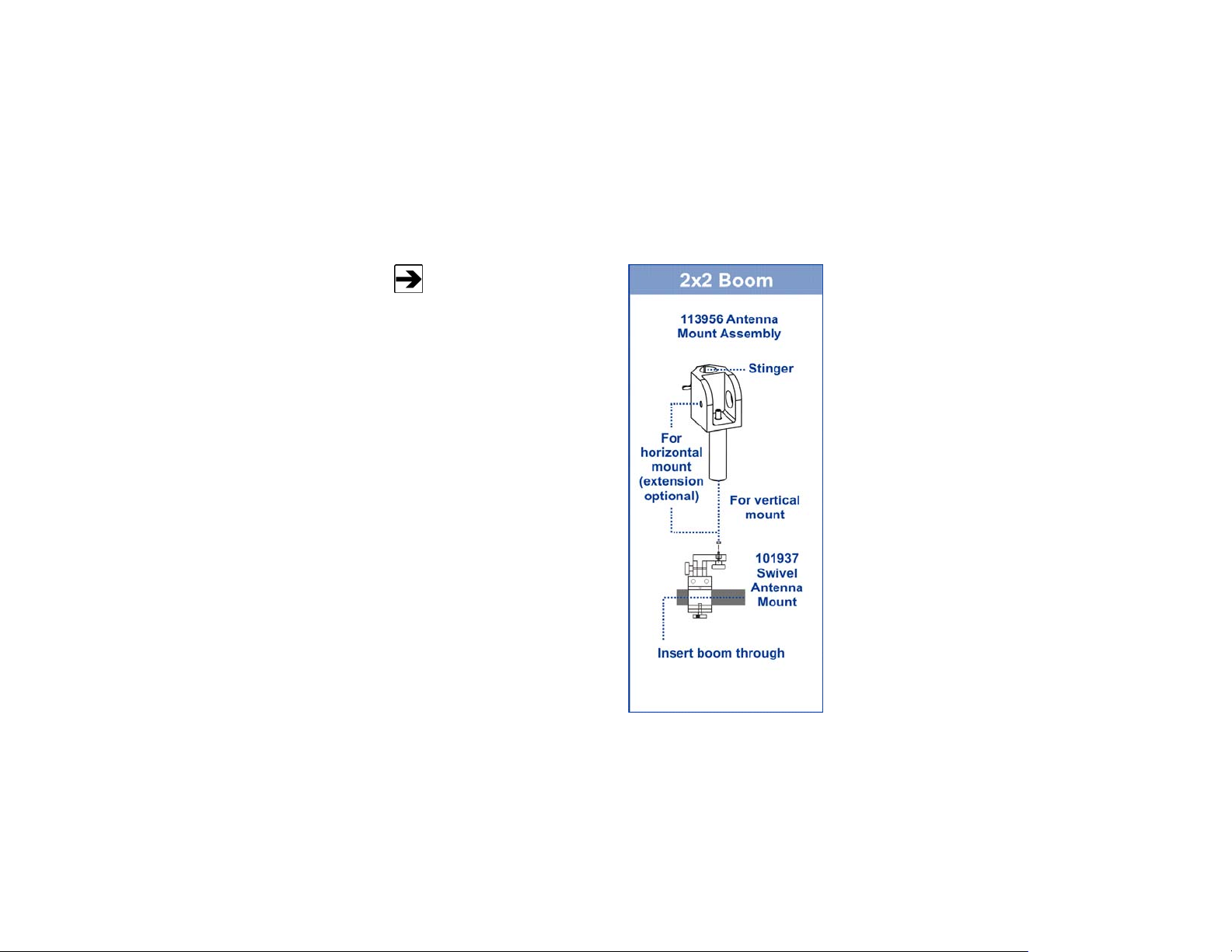
2X2 BOOM MOUNTING OPTIONS
Following are additional options for mounting the Model 3181/3183/3184 onto a
2x2 boom. See Using the Antenna Mount Assembly on a 4-TR on page 18 for
additional mounting and assembly information.
Contact the ETS-Lindgren Sales Department for information on ordering optional
mounting hardware.
2x2 boom refers to a typical
2-inch by 2-inch boom.
Mounting Instructions | 25
Page 26

Weatherizing Kit for Outdoor Testing (3181/3184 Only)
Do not use the Model 3183 for outdoor testing.
Do not use the weatherizing kit on the
Model 3183.
The antenna mount assembly ships with this
larger knob in place of the thumbscrew shown
in the following photos. The larger knob
provides the same functionality but provides
increased usability.
The Model 3181/3184 ships with a weatherizing kit to protect the cable
connection during outdoor use. The kit includes moldable plastic seal tape and
heavy-duty all-weather vinyl tape.
To order additional tape, see Replacement and Optional Parts on
page 13 for part number information.
26 | Mounting Instructions
Page 27

Follow these steps to apply the tapes:
STEP 1: WRAP MOLDABLE PLASTIC SEAL TAPE
• Make sure the
antenna shaft, cable,
and connectors are
clean and dry.
• Attach the antenna
cable to the antenna
connector.
• Start wrapping the
plastic seal tape
1.0 inch below the
base of the antenna
cable connector
cover, and wrap
upward to 1.0 inch
above the base of the
antenna shaft.
• As you wrap, overlap
the previous wrap
layer by 1/2 the width
of the tape.
Mounting Instructions | 27
Page 28

STEP 2: MOLD PLASTIC SEAL TAPE
• Press firmly and
uniformly over the
plastic seal tape to
mold it into place.
• Squeeze out any
trapped air as you
press the plastic
seal tape.
STEP 3: WRAP HEAVY-DUTY ALL-WEATHER VINYL TAPE
• Start wrapping
1/2 inch below
where the plastic
seal tape begins
and wrap upward to
1/2 inch above
where the seal tape
stops.
• As you wrap, stretch
the vinyl tape
slightly to avoid
creases and
bubbles.
• When done, inspect
the tape to make
sure everything is
covered and sealed.
28 | Mounting Instructions
Page 29

5.0 Typical Data
Model 3181
3181 A
NTENNA FACTOR / GAIN
Typical Data | 29
Page 30

3181 VSWR
30 | Typical Data
Page 31

Model 3183
3183 ANTENNA FACTOR / GAIN
Typical Data | 31
Page 32
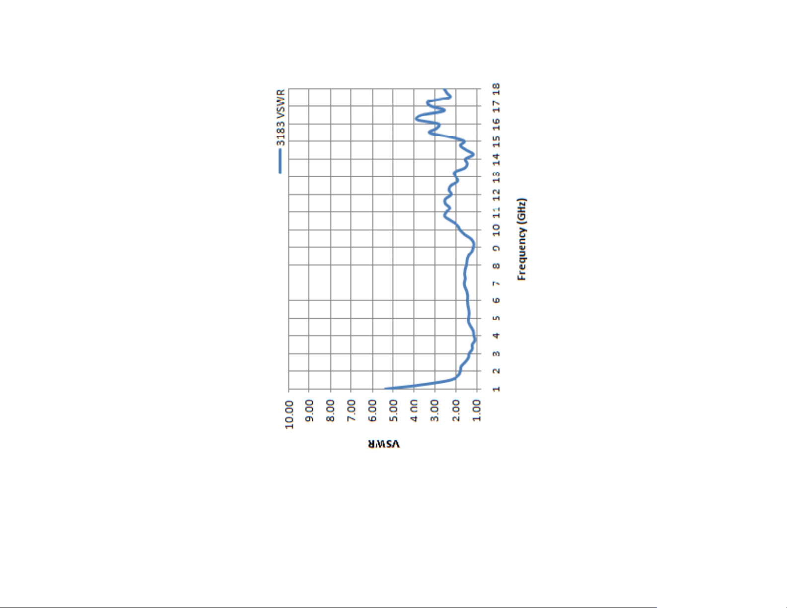
3183 VSWR
32 | Typical Data
Page 33
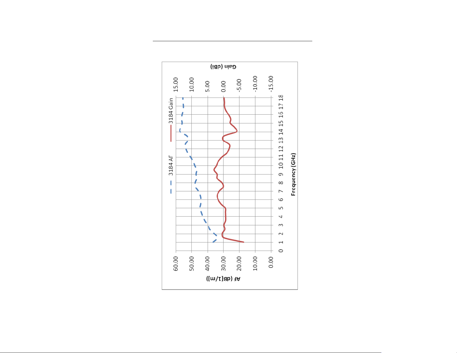
Model 3184
3184 A
NTENNA FACTOR / GAIN
Typical Data | 33
Page 34
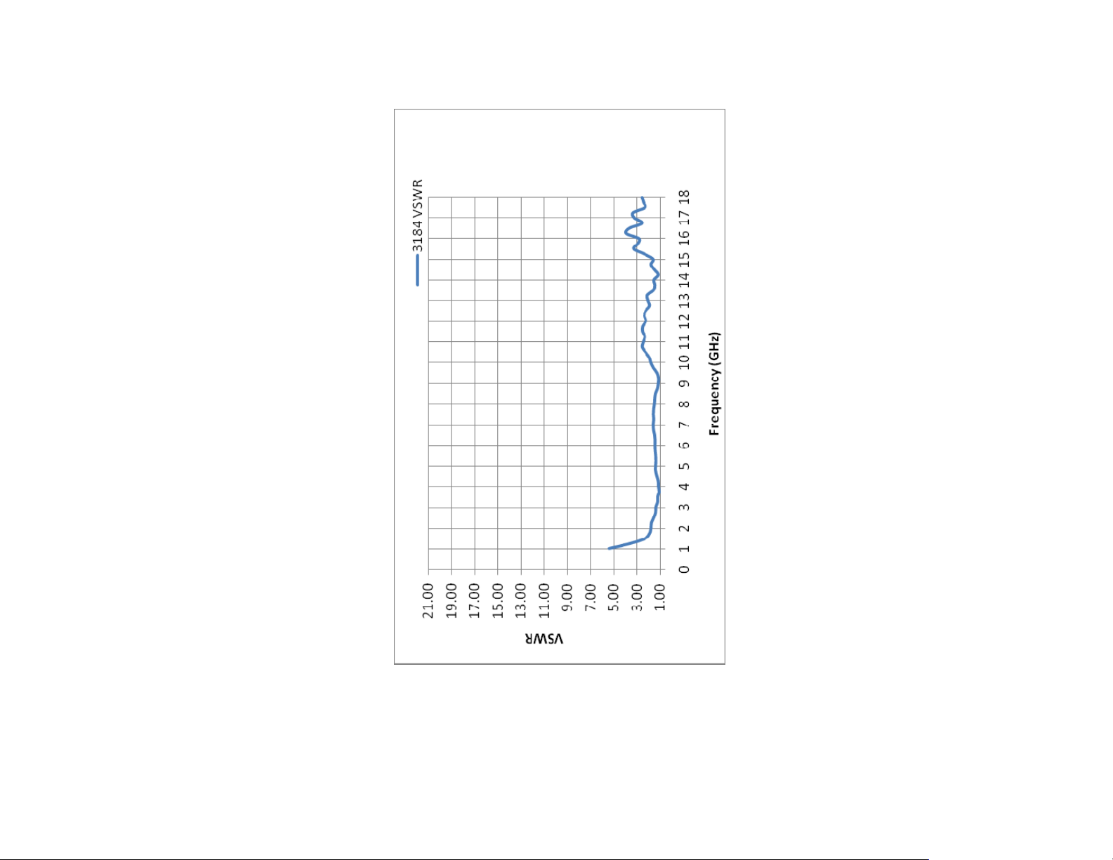
3184 VSWR
34 | Typical Data
Page 35
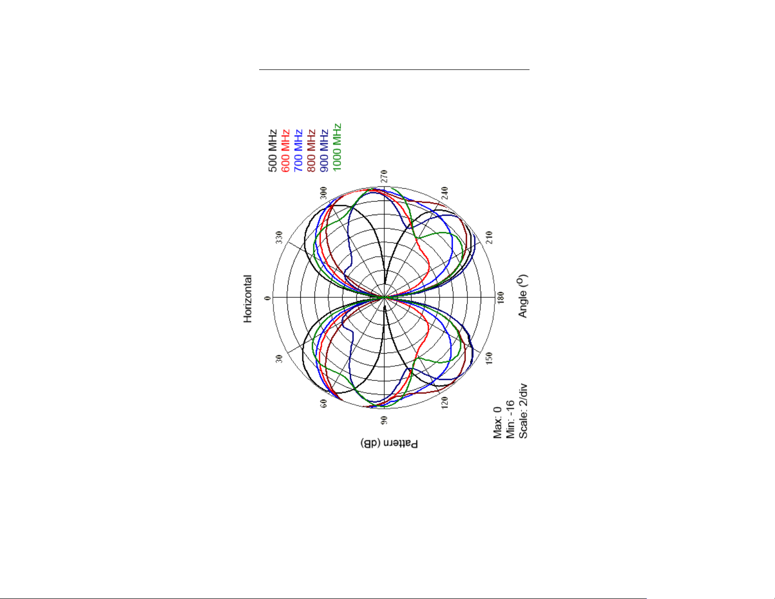
Typical E-Plane Patterns—Model 3181
3181 E-P
LANE AT
500 MHZ—1 GHZ
Typical Data | 35
Page 36

3181 E-P
LANE AT
2 GHZ –5 GHZ
36 | Typical Data
Page 37
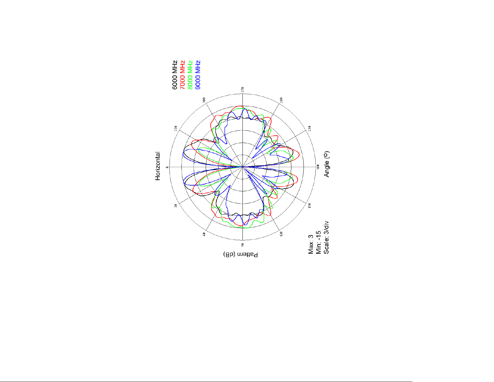
3181 E-P
LANE AT
6 GHZ–9 GHZ
Typical Data | 37
Page 38

3181 E-P
LANE AT
10 GHZ–13 GHZ
38 | Typical Data
Page 39
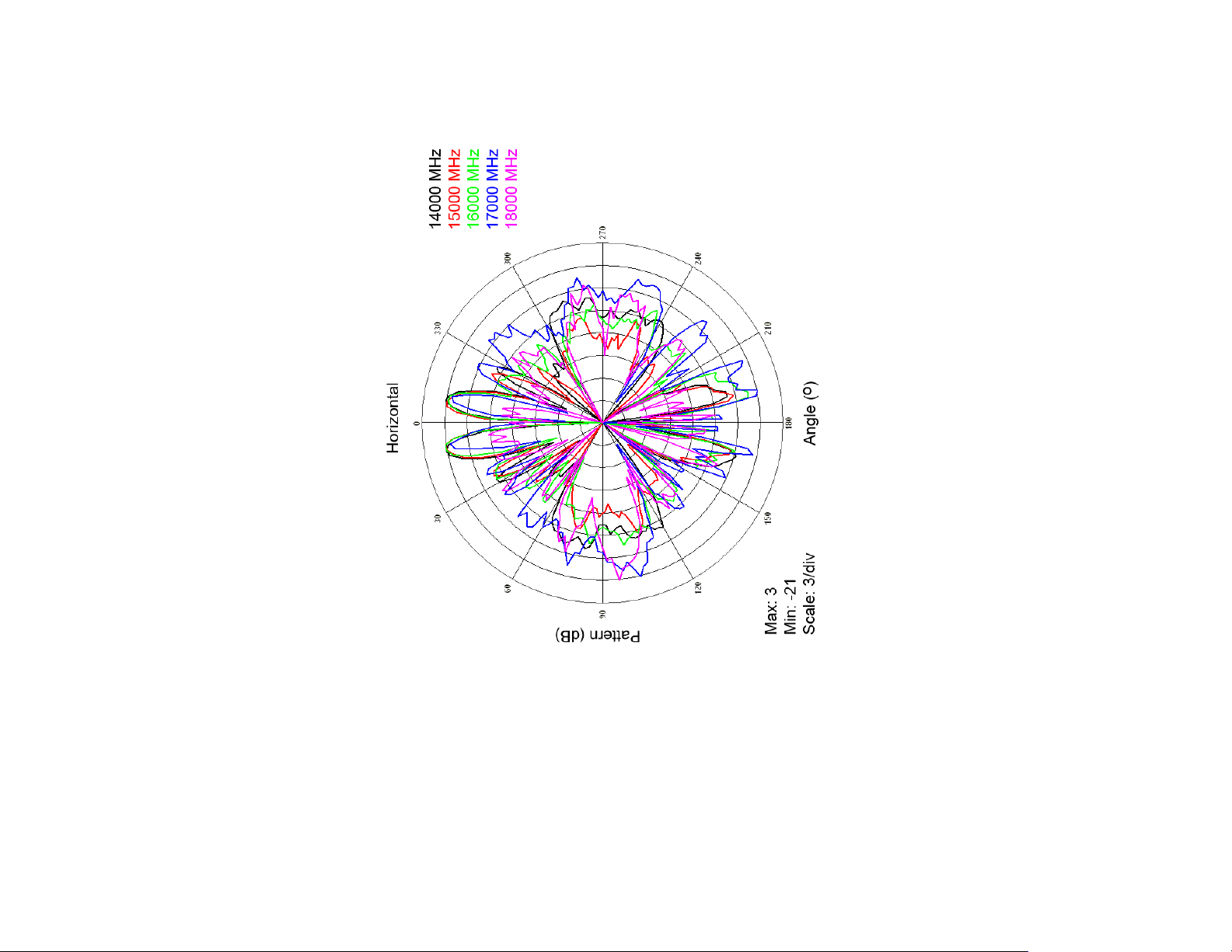
3181 E-P
LANE AT
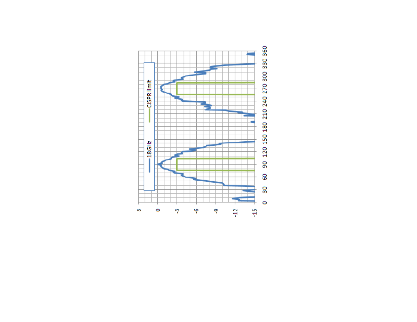
14 GHZ–18 GHZ
Typical Data | 39
Page 40
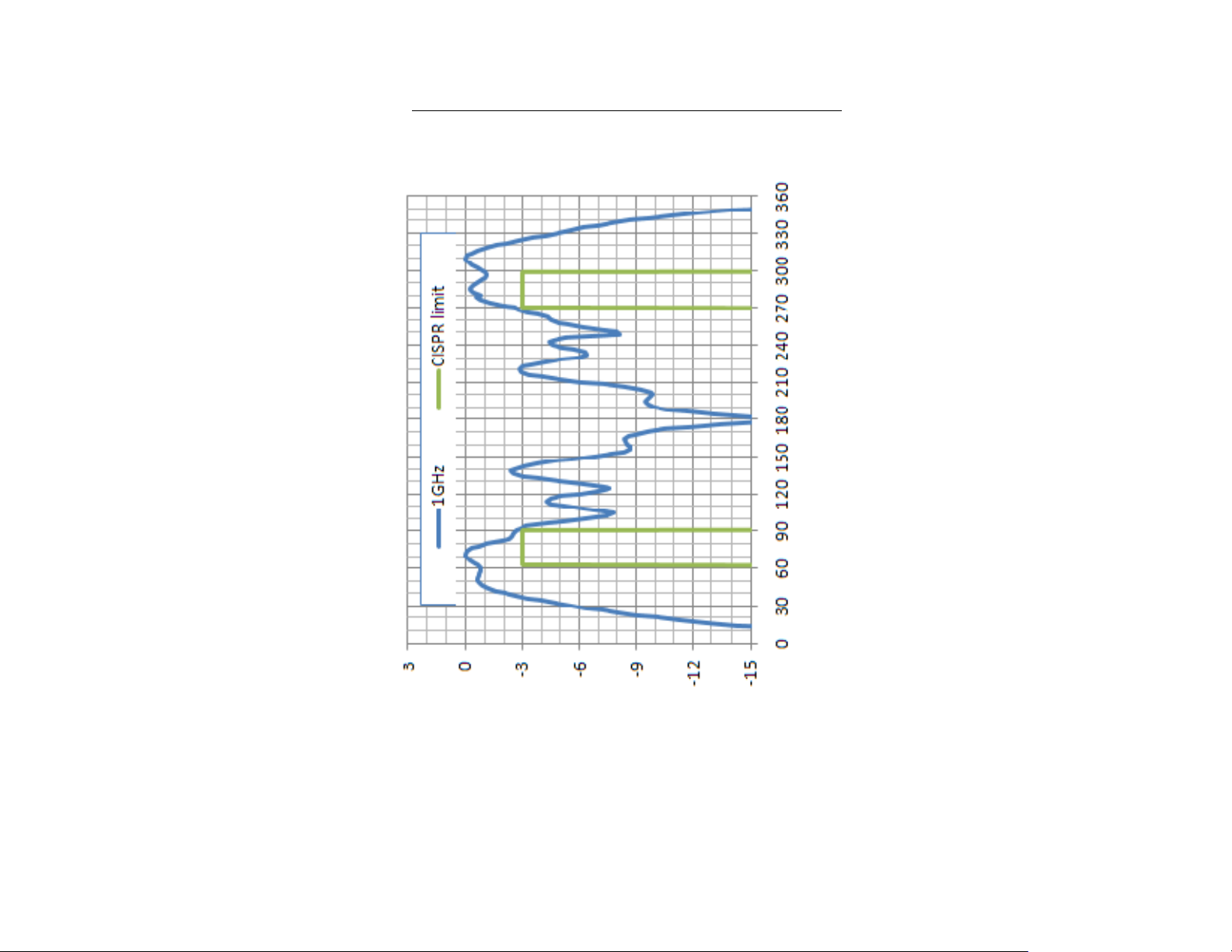
Typical E-Plane Patterns—Model 3183
3183 E-PLANE AT 1 GHZ
Degrees
40 | Typical Data
dB
Page 41
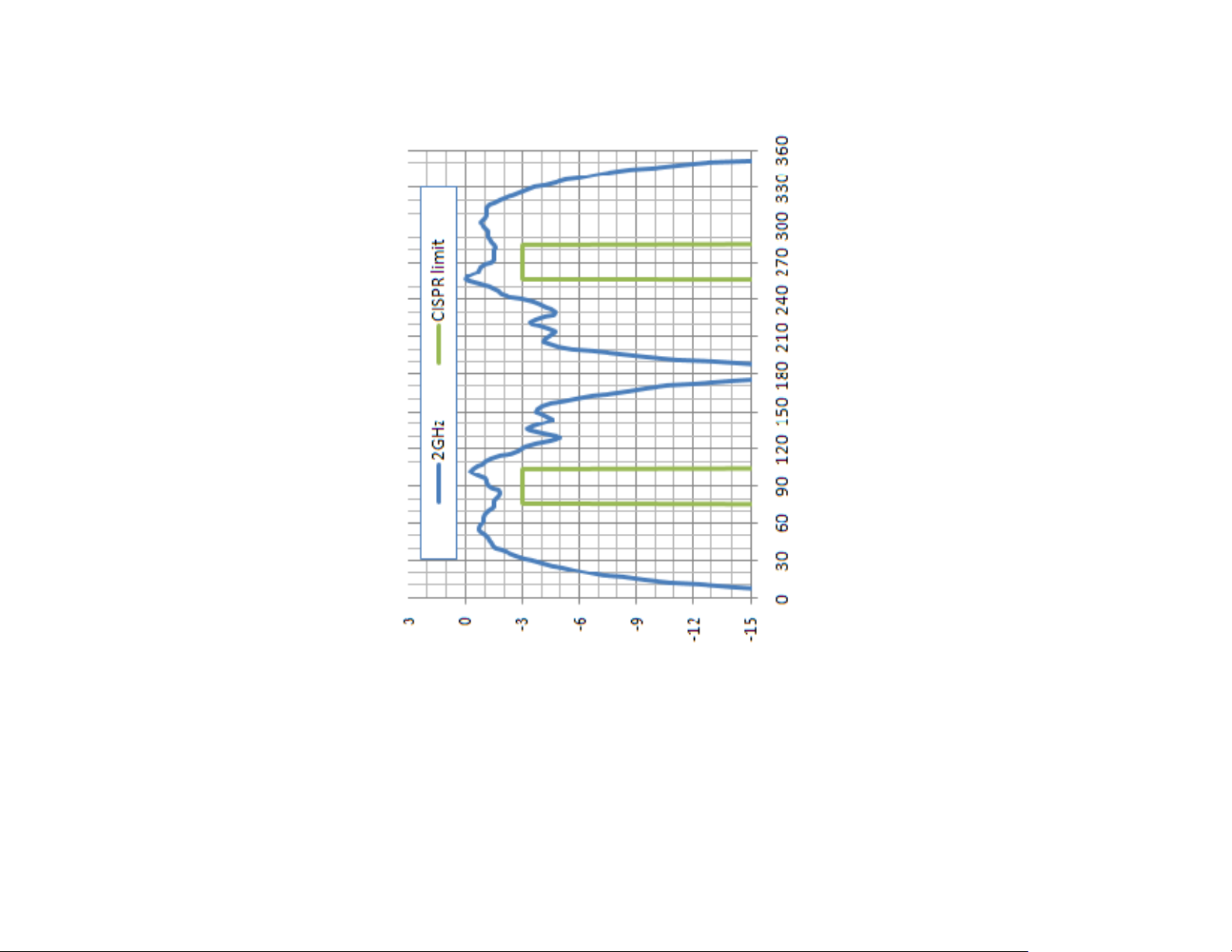
3183 E-PLANE AT 2 GHZ
Degrees
dB
Typical Data | 41
Page 42

3183 E-PLANE AT 3 GHZ
Degrees
42 | Typical Data
dB
Page 43

3183 E-PLANE AT 4 GHZ
Degrees
dB
Typical Data | 43
Page 44

3183 E-PLANE AT 5 GHZ
Degrees
44 | Typical Data
dB
Page 45

3183 E-PLANE AT 6 GHZ
Degrees
dB
Typical Data | 45
Page 46

3183 E-PLANE AT 7 GHZ
Degrees
46 | Typical Data
dB
Page 47

3183 E-PLANE AT 8 GHZ
Degrees
dB
Typical Data | 47
Page 48
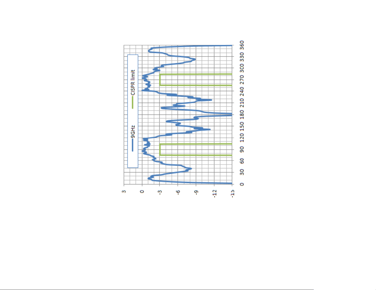
3183 E-PLANE AT 9 GHZ
Degrees
48 | Typical Data
dB
Page 49

3183 E-PLANE AT 10 GHZ
Degrees
dB
Typical Data | 49
Page 50
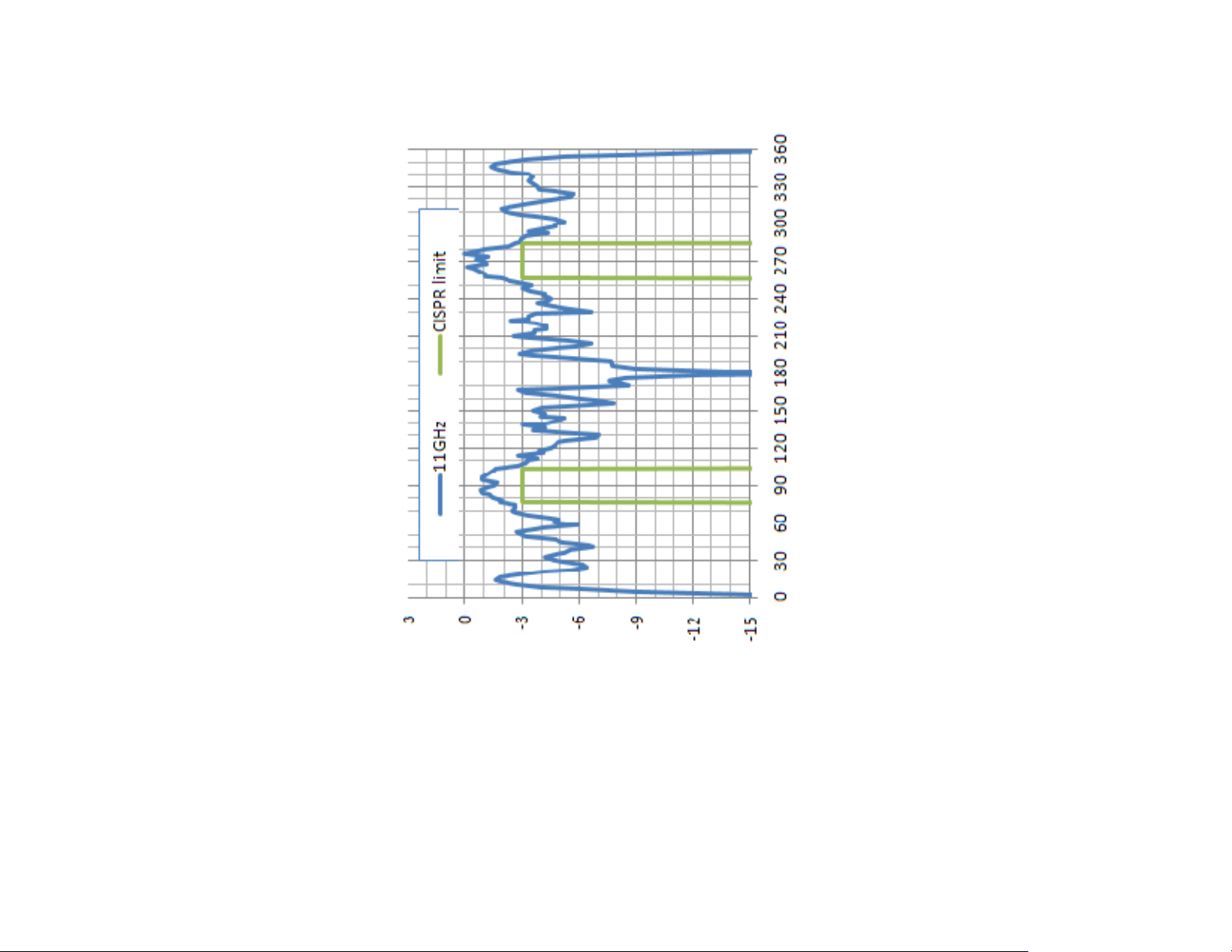
3183 E-PLANE AT 11 GHZ
Degrees
50 | Typical Data
dB
Page 51

3183 E-PLANE AT 12 GHZ
Degrees
dB
Typical Data | 51
Page 52
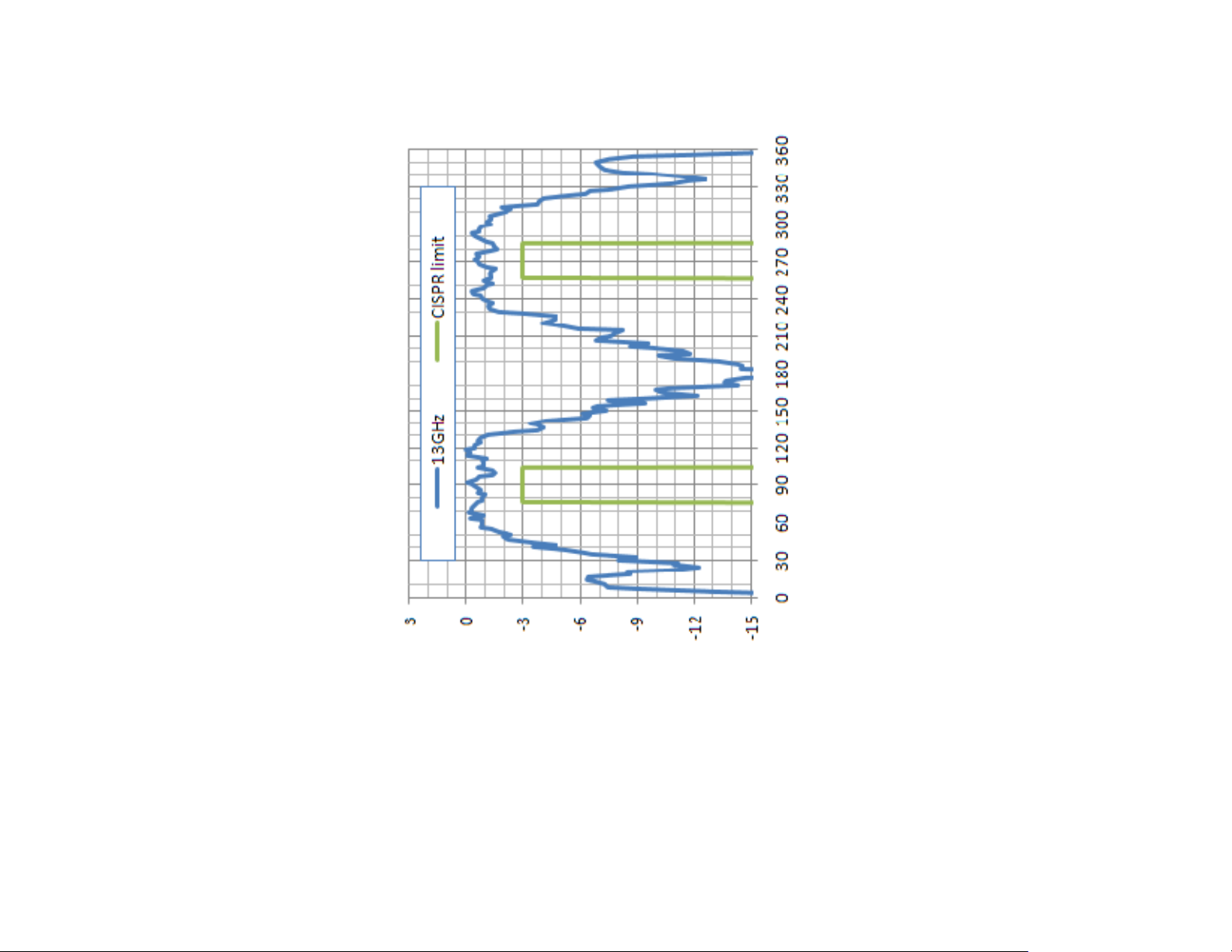
3183 E-PLANE AT 13 GHZ
Degrees
52 | Typical Data
dB
Page 53
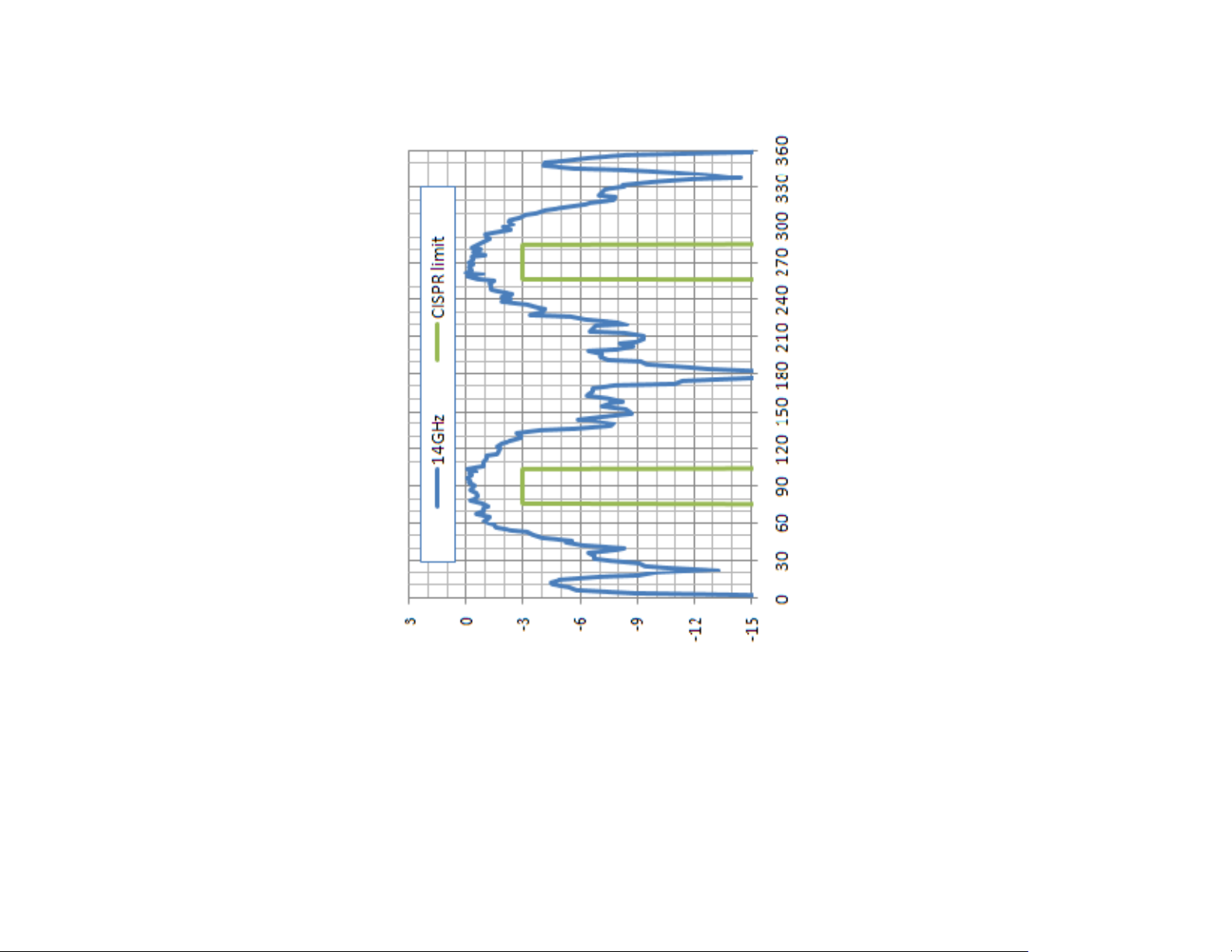
3183 E-PLANE AT 14 GHZ
Degrees
dB
Typical Data | 53
Page 54

3183 E-PLANE AT 15 GHZ
Degrees
54 | Typical Data
dB
Page 55
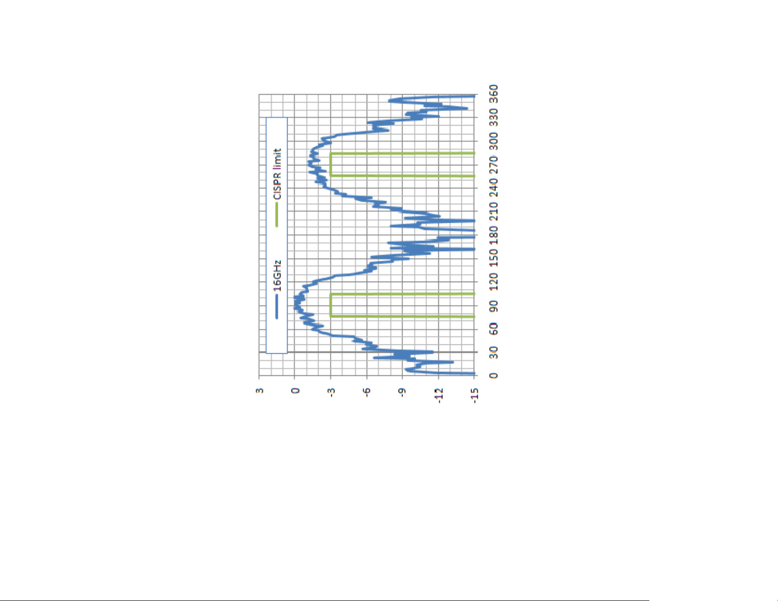
3183 E-PLANE AT 16 GHZ
Degrees
dB
Typical Data | 55
Page 56
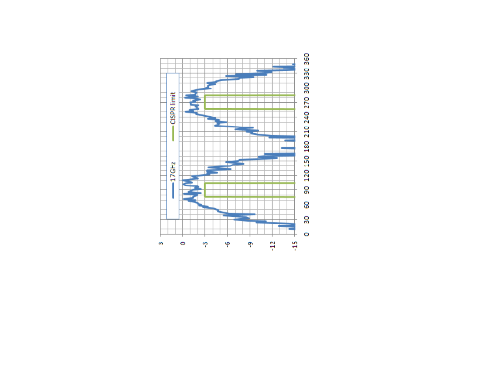
3183 E-PLANE AT 17 GHZ
Degrees
56 | Typical Data
dB
Page 57
3183 E-PLANE AT 18 GHZ
Degrees
dB
Typical Data | 57
Page 58

Typical H-Plane Patterns—Model 3183
3183 H-P
LANE AT
1 GHZ
58 | Typical Data
Page 59

3183 H-P
LANE AT 2 GHZ
–18 GHZ
Typical Data | 59
Page 60

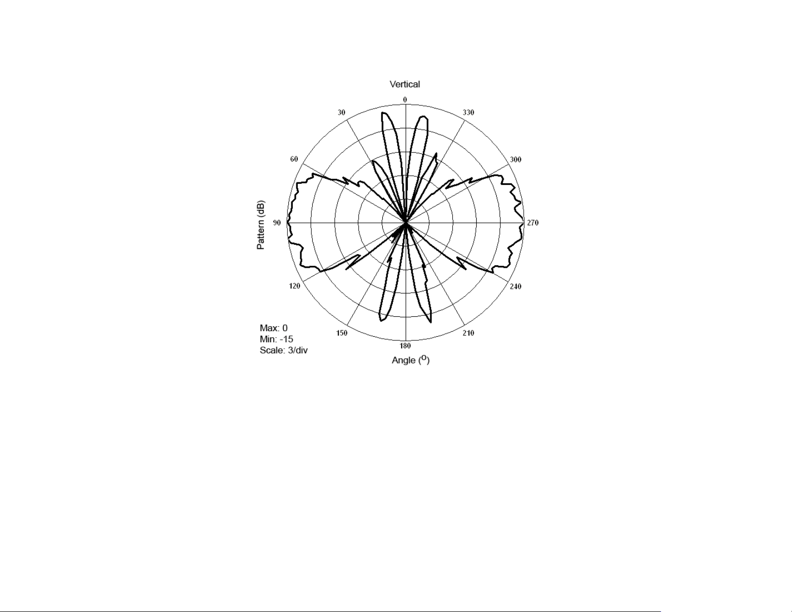
Typical E-Plane Patterns—Model 3184
3184 E-PLANE AT 2 GHZ–3 GHZ
60 | Typical Data
Page 61

3184 E-PLANE AT 4 GHZ–5 GHZ
Typical Data | 61
Page 62

3184 E-PLANE AT 6 GHZ–7 GHZ
62 | Typical Data
Page 63

3184 E-PLANE AT 8 GHZ–9 GHZ
Typical Data | 63
Page 64
3184 E-PLANE AT 10 GHZ–11 GHZ
64 | Typical Data
Page 65

3184 E-PLANE AT 12 GHZ–13 GHZ
Typical Data | 65
Page 66
3184 E-PLANE AT 14 GHZ–15 GHZ
66 | Typical Data
Page 67
3184 E-PLANE AT 16 GHZ–17 GHZ
Typical Data | 67
Page 68
3184 E-PLANE AT 18 GHZ
68 | Typical Data
Page 69

Typical H-Plane Patterns—Model 3184
3184 H-P
LANE AT
1 GHZ
Typical Data | 69
Page 70
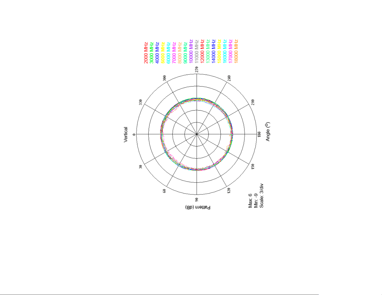
3184 H-P
LANE AT 2 GHZ
–18 GHZ
70 | Typical Data
Page 71

Appendix A: Warranty
See the Product Information Bulletin included with your shipment for
the complete ETS-Lindgren warranty for your Model 3181/3183/3184.
DURATION OF WARRANTIES FOR MODEL 3181/3183/3184
All product warranties, except the warranty of title, and all remedies for warranty
failures are limited to two years.
Product Warranted Duration of Warranty Period
Model 3181 End Fed
Mini-Bicon Antenna
Model 3183 End Fed
Mini-Bicon Antenna
Model 3184 End Fed
Mini-Bicon Antenna
2 Years
2 Years
2 Years
Warranty | 71
 Loading...