

Page 1
Model 3182
Broadband Biconical
Antenna
User Manual
Page 2

ii |
ETS-Lindgren L.P. reserves the right to make changes to any product described
herein in order to improve function, design, or for any other reason. Nothing
contained herein shall constitute ETS-Lindgren L.P. assuming any liability
whatsoever arising out of the application or use of any product or circuit
described herein. ETS-Lindgren L.P. does not convey any license under its
patent rights or the rights of others.
© Copyright 2009 by ETS-Lindgren L.P. All Rights Reserved. No part of this
document may be copied by any means without written permission from
ETS-Lindgren L.P.
Trademarks used in this document: The ETS-Lindgren logo is a trademark of
ETS-Lindgren L.P.
Revision Record
MANUAL,3182 MINI-BICONICAL ANTENNA | Part #399294, Rev. A
Revision Description Date
A Initial Release February, 2009
Page 3

| iii
Table of Contents
Notes, Cautions, and Warnings ................................................ v
1.0 Introduction .......................................................................... 7
Tripod Options ............................................................................................... 8
ETS-Lindgren Product Information Bulletin ................................................... 9
2.0 Maintenance ....................................................................... 11
Annual Calibration ....................................................................................... 11
Replacement and Optional Parts ................................................................. 11
Service Procedures ..................................................................................... 12
3.0 Specifications ..................................................................... 13
Electrical Specifications ............................................................................... 13
Physical Specifications ................................................................................ 13
4.0 Assembly Instructions ...................................................... 15
5.0 Mounting Instructions ....................................................... 17
Using Included Mounting Adapters .............................................................. 17
Using the Stinger Mount .............................................................................. 19
Additional Mounting Options ........................................................................ 20
4-TR Mounting Options........................................................................ 20
7-TR and Mast Mounting Options ........................................................ 21
2x2 Boom Mounting Options ............................................................... 22
6.0 Application ......................................................................... 23
7.0 Typical Data ........................................................................ 25
Antenna Factor ............................................................................................ 25
Gain ............................................................................................................. 26
VSWR .......................................................................................................... 27
Typical Radiation Patterns ........................................................................... 28
Model 3182, 400 MHz–700 MHz ......................................................... 28
Model 3182, 700 MHz–1000 MHz ....................................................... 29
Appendix A: Warranty ............................................................. 31
Page 4

iv |
This page intentionally left blank.
Page 5
| v
Notes, Cautions, and Warnings
Note: Denotes helpful information intended to
provide tips for better use of the product.
Caution: Denotes a hazard. Failure to follow
instructions could result in minor personal injury
and/or property damage. Included text gives proper
procedures.
Warning: Denotes a hazard. Failure to follow
instructions could result in SEVERE personal injury
and/or property damage. Included text gives proper
procedures.
See the ETS-Lindgren Product Information Bulletin for safety,
regulatory, and other product marking information.
Page 6

vi |
This page intentionally left blank.
Page 7

Introduction | 7
1.0 Introduction
The ETS-Lindgren Model 3182 Broadband Biconical Antenna is designed for
optimal performance across the frequency range of 30 MHz to 1 GHz. The
uniquely-designed elements provide an omni-directional pattern without the main
radiation beam splitting into two lobes in the elevation cut.
In addition to covering the traditional frequency range EMC measurements, the
Model 3182 covers all the VHF and part of the UHF bands, making it ideal for
spectrum monitoring of FM, TV, and some cellular phones.
The Model 3182 is designed to have a radiation pattern that is dipole-like across
the range. The elements have been optimized to avoid any splitting of the main
radiation beam in the elevation cut.
The Model 3182 is ideal for surveillance and spectrum monitoring. The
omni-directional patterns can receive signal from every direction in the azimuth.
The Model 3182 includes a stinger mount and standard mounting hardware. For
the variety of mounting options available for the Model 3182, see
Mounting Instructions on page 17.
Page 8
8 | Introduction
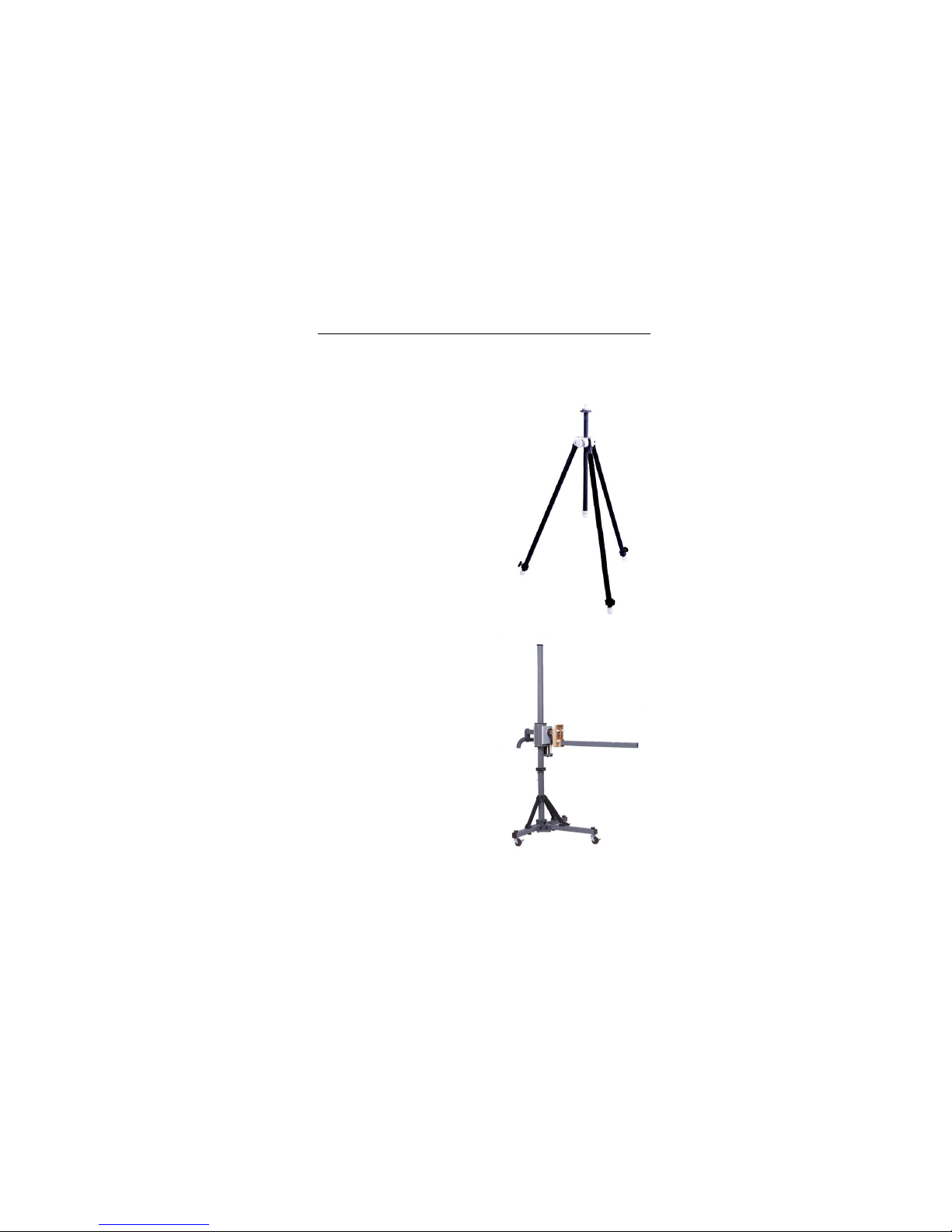
Tripod Options
ETS-Lindgren offers the following nonmetallic, non-reflective tripods for use at
both indoor and outdoor EMC test sites.
• Model 4-TR—Constructed of linen
phenolic and delrin, designed with an
adjustable center post for precise
height adjustments. Maximum height
is 2.0 m (80.0 in), and minimum height
is 94 cm (37.0 in). This tripod can
support up to an 11.8 kg (26.0 lb)
load.
• Model 7-TR—Constructed of PVC
and fiberglass components, providing
increased stability for physically large
antennas. The unique design allows
for quick assembly, disassembly, and
convenient storage. Allows several
different configurations, including
options for manual or pneumatic
polarization. Quick height adjustment
and locking wheels provide ease of
use during testing. Maximum height is
2.17 m (85.8 in), with a minimum
height of .8 m (31.8 in). This tripod
can support a 13.5 kg (30 lb) load.
Page 9

Introduction | 9
ETS-Lindgren Product Information Bulletin
See the ETS-Lindgren Product Information Bulletin included with your shipment
for the following:
• Warranty information
• Safety, regulatory, and other product marking information
• Steps to receive your shipment
• Steps to return a component for service
• ETS-Lindgren calibration service
• ETS-Lindgren contact information
Page 10

10 | Introduction
This page intentionally left blank.
Page 11

Maintenance | 11
2.0 Maintenance
Before performing any maintenance, follow
the safety information in the ETS-Lindgren
Product Information Bulletin included with
your shipment.
Maintenance of the Model 3182 is limited to
external components such as cables or
connectors.
If you have any questions concerning
maintenance, contact ETS-Lindgren
Customer Service.
Annual Calibration
See the Product Information Bulletin included with your shipment for information
on ETS-Lindgren calibration services.
Replacement and Optional Parts
Following are the part numbers for ordering replacement or optional parts for the
Model 3182 Broadband Biconical Antenna.
Part Description Part Number
Clamp Block 102108
Support Base 101942B
Support Rod White 100733
For additional/optional mounting hardware, see Additional Mounting
Options on page 17.
WARRANTY
Page 12

12 | Maintenance
Service Procedures
For the steps to return a system or system component to ETS-Lindgren for
service, see the Product Information Bulletin included with your shipment.
Page 13

Specifications | 13
3.0 Specifications
Electrical Specifications
Frequency Range: 30 MHz–1 GHz
VSWR Ratio (Average): <2.5:1
Maximum Continuous Power: 200 W
Impedance: 50 Ω
Connector: Type N female
Physical Specifications
Length: 53.34 cm
22.0 in
Width/Diameter: 41.3 cm
16.2 in
Height: 62.7 cm
24.0 in
Page 14

14 | Specifications
This page intentionally left blank.
Page 15

Assembly Instructions | 15
4.0 Assembly Instructions
Before connecting any components, follow the
safety information in the ETS-Lindgren
Product Information Bulletin included with your
shipment.
The Model 3182 Broadband Biconical Antenna is shipped unassembled, and
includes these parts:
• Balun – includes attached stinger mount
• Biconical element (2)
• Belleville washer (2)
• Clamp block
• Support rod and base
Page 16

16 | Assembly Instructions
To assemble the Model 3182:
1. Slide a belleville washer onto the threaded screw end of one of the
biconical elements.
2. Line up the screw threads with the receptacle hole on the balun and
turn the biconical element until it is firmly secured in the balun.
Do not cross thread this connection or
permanent damage to the joint could occur.
3. Repeat step 1 and step 2 using the remaining washer and biconical
element.
Page 17

Mounting Instructions | 17
5.0 Mounting Instructions
Before connecting any components, follow the
safety information in the ETS-Lindgren
Product Information Bulletin included with your
shipment.
Using Included Mounting Adapters
The Model 3180 Mini-Bicon Antenna ships with these mounting adapters, used to
mount the antenna to a 4-TR tripod:
• 102108 Clamp Block—Uses
standard 7/8–14 threads and comes
with a 1/4–20 thread adapter for
mounting to an ETS-Lindgren tripod
or most other tripods.
• 100733 Support Rod
• 101942B Support Base
Page 18

18 | Mounting Instructions
To use these adapters to mount the Model 3182 to a 4-TR tripod:
Shown mounted with clamp block and support rod
(support base not shown)
1. Assemble the clamp block, support base, and support rod, and attach
the support base to the 4-TR tripod.
2. Unscrew the clamp block latch and open the top.
3. Insert the balun into the clamp block and close the top over the balun.
4. Move the latch to the closed position and tighten so the balun is held
securely.
5. Attach the cable to the output connector on the antenna.
Page 19

Mounting Instructions | 19
Using the Stinger Mount
The stinger on the Model 3182 enables you to mount to antenna directly to an
ETS-Lindgren 7-TR Tripod Positioner.
Additional hardware is required to use the stinger to mount the
Model 3182 to a mast. For information on ordering optional mounting
hardware, contact the ETS-Lindgren Sales Department.
Do not use the stinger to mount the Model 3182 onto a 4-TR tripod.
Page 20

20 | Mounting Instructions
Additional Mounting Options
4-TR MOUNTING OPTIONS
Following are additional options for mounting the Model 3182 onto an
ETS-Lindgren 4-TR tripod. Contact the ETS-Lindgren Sales Department for
information on ordering optional mounting hardware.
Page 21

Mounting Instructions | 21
7-TR AND MAST MOUNTING OPTIONS
The stinger on the Model 3182 enables you to mount to antenna directly to an
ETS-Lindgren 7-TR Tripod Positioner. Following are additional options for
mounting the Model 3182 onto an ETS-Lindgren 7-TR Tripod Positioner.
Contact the ETS-Lindgren Sales Department for information on ordering optional
mounting hardware.
Mast refers to 2070 Series, 2075, and 2175 Antenna Towers.
7-TR refers to 109042, 106328, and 108197 booms:
• 109042 boom—Straight boom; for general antenna mounting on a
7-TR
• 106328 boom—Offset boom; for general antenna mounting on a
7-TR with pneumatic or manual polarization
• 108197 boom—Center rotate boom; for rear-mount stinger-type
antennas only.
Page 22

22 | Mounting Instructions
2X2 BOOM MOUNTING OPTIONS
Following are additional options for mounting the Model 3182 onto a 2x2 boom.
Contact the ETS-Lindgren Sales Department for information on ordering optional
mounting hardware.
2x2 boom refers to a typical 2-inch by 2-inch boom.
Page 23

Application | 23
6.0 Application
The Model 3182 Broadband Biconical Antenna is ideally suited for swept site
attenuation measurements per ANSI and FCC specifications. The Model 3182
can be used for horizontal and as vertical site attenuation measurements. A
20 dB pre-amplifier is recommended in line with the receive antenna to minimize
the required transmitted power and to reduce the possibility of saturation of the
transmitting antenna. The maximum continuous input power to the Model 3182 is
250 mW.
When the Model 3182 is used vertically, the same element orientation need not
be maintained from measurement to measurement. The Model 3182 exhibits
excellent symmetrical performance, and test repeatability is assured by the balun
design.
Each antenna is calibrated during manufacturing. The results of the calibration
are tabulated as gain and antenna factor vs. frequency for use in Specification
Compliance Testing. Typical data for the Model 3182 is provided in the next
section.
Page 24

24 | Application
This page intentionally left blank.
Page 25

Typical Data | 25
7.0 Typical Data
Antenna Factor
Page 26

26 | Typical Data
Gain
Page 27

Typical Data | 27
VSWR
Page 28

28 | Typical Data
Typical Radiation Patterns
MODEL 3182, 400 MHZ–700 MHZ
Page 29

Typical Data | 29
MODEL 3182, 700 MHZ–1000 MHZ
Page 30

30 | Typical Data
This page intentionally left blank.
Page 31

Warranty | 31
Appendix A: Warranty
See the Product Information Bulletin included with your shipment for
the complete ETS-Lindgren warranty for your Model 3182 Broadband
Biconical Antenna.
DURATION OF WARRANTIES FOR MODEL 3182
All product warranties, except the warranty of title, and all remedies for warranty
failures are limited to two years.
Product Warranted Duration of Warranty Period
Model 3182 Broadband
Biconical Antenna
2 Years
 Loading...