

Page 1
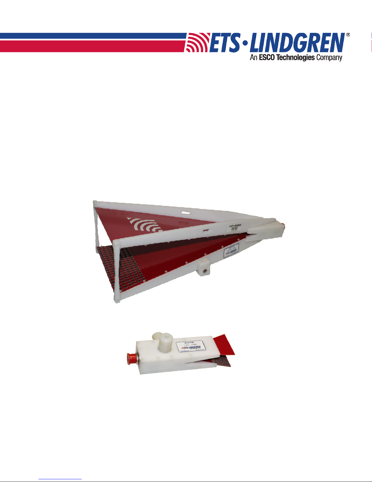
TEM Horn Antennas
Models 3166 and 3167
User Manual
399387 Rev AOctober 2018
Page 2

Page 3
ETS-Lindgren Inc. reserves the right to make changes to any products herein to improve functioning or design.
Although the information in this document has been carefully reviewed and is believed to be reliable, ETS-Lindgren
does not assume any liability arising out of the application or use of any product or circuit described herein; nor does
it convey any license under its patent rights nor the rights of others. All trademarks are the property of their respective
owners.
© Copyright 2018 by ETS-Lindgren Inc. All Rights Reserved. No part of this document may be copied by any
means without written permission from ETS-Lindgren Inc.
Trademarks used in this document: The ETS-Lindgren logo is a registered trademark of ETS-Lindgren, Inc.
Revision Record
MANUAL, 3166 and 3167 | Part # 399387 Rev A
Revision Description Date
A Initial Release October, 2018
3
Page 4

4
Page 5

TABLE OF CONTENTS
NOTES, CAUTIONS, AND WARNINGS 6
SAFETY INFORMATION 6
GENERAL SAFETY CONSIDERATIONS 6
INTRODUCTION 7
Standard Conguration . . . . . . . . . . . . . . . . . . . . . . . . . . . . . 7
Tripod . . . . . . . . . . . . . . . . . . . . . . . . . . . . . . . . . . . 7
ETS-Lindgren Product Information Bulletin . . . . . . . . . . . . . . . . . . . . . 7
MAINTENANCE 8
Annual Calibration . . . . . . . . . . . . . . . . . . . . . . . . . . . . . . . 8
Replacement and Optional Parts . . . . . . . . . . . . . . . . . . . . . . . . . 8
Service Procedures . . . . . . . . . . . . . . . . . . . . . . . . . . . . . .8
SPECIFICATIONS 9
3166 Electrical Specications . . . . . . . . . . . . . . . . . . . . . . . . . . . 9
3166 Physical Specications . . . . . . . . . . . . . . . . . . . . . . . . . . . 9
3167 Electrical Specications . . . . . . . . . . . . . . . . . . . . . . . . . . . 9
3167 Physical Specications . . . . . . . . . . . . . . . . . . . . . . . . . . . 9
MOUNTING INSTRUCTIONS 10
Using Included Mounting Adapters . . . . . . . . . . . . . . . . . . . . . . . . 10
3166 Mounting Adapters. . . . . . . . . . . . . . . . . . . . . . . . . . . 10
3167 Mounting Adapters. . . . . . . . . . . . . . . . . . . . . . . . . . . 10
TYPICAL DATA 11
3166 VSWR . . . . . . . . . . . . . . . . . . . . . . . . . . . . . . . . 11
3167 VSWR . . . . . . . . . . . . . . . . . . . . . . . . . . . . . . . . 11
3166 Forward Power . . . . . . . . . . . . . . . . . . . . . . . . . . . . . 12
3167 Forward Power . . . . . . . . . . . . . . . . . . . . . . . . . . . . . 12
FIeld Uniformity . . . . . . . . . . . . . . . . . . . . . . . . . . . . . . . 13
Minimum Field Uniformity Grid Dimensions . . . . . . . . . . . . . . . . . . . . 16
Appendix A: Warranty 17
DURATION OF WARRANTIES FOR MODELS 3166 AND 3167 TEM HORN ANTENNAS 17
5
Page 6
NOTES, CAUTIONS, AND WARNINGS
Note: Denotes helpful information intended to provide tips for better use of
the product.
Caution: Denotes a hazard. Failure to follow instructions could result in
minor personal injury and/or property damage. Included text gives proper
procedures.
Warning: Denotes a hazard. Failure to follow instructions could result in
SEVERE personal injury and/or property damage. Included text gives proper
procedures.
SAFETY INFORMATION
Refer to Manual: When product is marked with this symbol, see the
instruction manual for additional information. If the instruction manual has
been misplaced, download it from www.ets-lindgren.com, or contact
ETS-Lindgren Customer Service.
High Voltage: Indicates presence of hazardous voltage. Unsafe practice
could result in severe personal injury or death.
High Voltage: Indicates presence of hazardous voltage. Unsafe practice
could result in severe personal injury or death.
Protective Earth Ground (Safety Ground): Indicates protective earth
terminal. You should provide uninterruptible safety earth ground from the
main power source to the product input wiring terminals, power cord, or
supplied power cord set.
See the ETS-Lindgren Product Information Bulletin for safety, regulatory, and other product
marking information.
GENERAL SAFETY CONSIDERATIONS
Only qualied personnel should operate (or service) this equipment.
6
Page 7

INTRODUCTION
The ETS-Lindgren Model 3166 and 3167 TEM Horn Antennas generate homogeneous elds in the frequency range
of 380 MHz to 6 GHz specically for immunity testing in close proximity as per the IEC/EN 61000-4-39 standard. The
3166 model operates from 380 MHz to 3 GHz with less than 7:1 VSWR from 400 MHz to 700 MHz and 3:1 VSWR from
700 MHz and above. The 3167 operates from 3 GHz to 6 GHz with less than 2:1 VSWR.
Standard Conguration
Tripod
The 4-TR tripod is constructed of linen phenolic and delrin, designed with an adjustable center post for precise
height adjustments.
Maximum Height 2.0 m (80.0 in)
Minimum Height 94 cm (37.0 in)
Maximum Load 11.8 kg (26.0 lb)
ETS-Lindgren Product Information Bulletin
See the ETS-Lindgren Product Information Bulletin included with your shipment for the following:
• Warranty information
• Safety, regulatory, and other product marking information
• Steps to receive your shipment
• Steps to return a component for service
• ETS-Lindgren calibration service
• ETS-Lindgren contact information
7
Page 8

MAINTENANCE
Before performing any maintenance, follow the safety information in the ETS-Lindgren Product
Information Bulletin included with your shipment.
Maintenance of the Model 3166 and 3167 is limited to external components such as
WARRANTY
cables or connectors.
If you have any questions concerning maintenance, contact ETS-Lindgren Customer Service.
Annual Calibration
See the Product Information Bulletin included with your shipment for information on ETS-Lindgren
calibration services.
Replacement and Optional Parts
ETS-Lindgren may substitute a similar part or new part number with the same functionality for another
part/part number. Contact ETS-Lindgren for questions about part numbers and ordering parts.
Following are the part numbers for ordering replacement or optional parts for the Model 3166.
Part Description Part Number
4-TR Tripod 4-TR
4-TR Adjustable Mount 123627
Following are the part numbers for ordering replacement or optional parts for the Model 3167.
Part Description Part Number
4-TR Tripod 4-TR
Post Mount 121268
Service Procedures
For the steps to return a system or system component to ETS-Lindgren for service, see the Product Information
Bulletin included with your shipment.
8
Page 9

SPECIFICATIONS
3166 Electrical Specications
Application IEC / EN 61000-4-39
Frequency Range 380 MHz to 3 GHz
VSWR 7:1 (400 MHz to 700 MHz)
Maximum Continuous Power 250 W
Impedance (Nominal) 50 Ω
Connector N type, female
3166 Physical Specications
Width 21.6 cm (8.5 in)
Depth 47.6 cm (18.75 in)
Height 13.2 cm (5.2 in)
Approximate Weight 3.6 kg (8 lb)
3167 Electrical Specications
3:1 (700 MHz to 3 GHz)
Application IEC / EN 61000-4-39
Frequency Range 3 GHz to 6 GHz
VSWR 2:1
Maximum Continuous Power 250 W
Impedance (Nominal) 50 Ω
Connector N type, female
3167 Physical Specications
Width 7.9 cm (3.1 in)
Depth 17.3 cm (6.8 in)
Height 6.4 cm (2.5 in)
Approximate Weight 0.2 kg (0.4 lb)
9
Page 10

MOUNTING INSTRUCTIONS
Before connecting any components, follow the safety information in the ETS-Lindgren Product
Information Bulletin included with your shipment.
Model 3166 and Model 3167 are precision measurement devices. Handle with care.
Using Included Mounting Adapters
3166 Mounting Adapters
The Model 3166 TEM Horn Antenna ships with this mounting adapter:
• 123627 4-TR Mount, 3166 Retro
with 7/8 – 14 thread receptacle
• 105861B 1/4–20 Thread Insert
To use this adapter to mount the Model 3166 to a tripod:
1. Located on the bottom of the 4-TR Mount, 3166 Retro is a 7/8 – 14 thread receptacle; if you need to
convert to a 1/4 - 20 receptacle, insert the 1/4 - 20 thread insert into the polarizing adapter.
2. Attach the 4-TR Mount, 3166 Retro to tripod.
3167 Mounting Adapters
The Model 3167 TEM Horn Antenna ships with 2 post mount adapters attached to the antenna:
• 121268 Post Mount with
1/4 - 20 Thread Receptacle
To use this adapter to mount the Model 3167 to a tripod:
1. 1/4 - 20 thread receptacles are located on the ends of each post mount.
2. Attach post mount to tripod.
10
Page 11

TYPICAL DATA
3166 VSWR
3167 VSWR
11
Page 12

3166 Forward Power
3167 Forward Power
12
Page 13

FIeld Uniformity
13
Page 14

14
Page 15

15
Page 16

Minimum Field Uniformity Grid Dimensions
The following table lays out the minimum grid dimensions in x and y directions that will satisfy the -4 dB Field
Uniformity requirement as per IEC / EN 61000-4-39 standard.
Measured Dimensions
Freq (MHz) Min x (cm) Min y (cm)
400 40 30
425 55 25
450 55 30
475 55 35
500 55 25
525 55 25
550 55 25
575 55 30
600 55 25
625 55 30
650 55 30
675 55 30
700 55 35
750 55 25
800 55 30
850 55 25
900 55 30
950 55 25
1000 55 25
1500 55 20
2000 55 15
2500 55 10
3000 40 10
3000 40 10
3500 40 10
4000 40 10
4500 40 10
5000 40 10
5500 40 10
6000 40 10
16
Page 17

Appendix A: Warranty
See the Product Information Bulletin included with your shipment for the complete ETS Lindgren
warranty for your Model 3166 or Model 3167 TEM Horn Antenna.
DURATION OF WARRANTIES FOR MODELS 3166 AND 3167 TEM HORN ANTENNAS
All product warranties, except the warranty of title, and all remedies for warranty failures are limited to one year.
Product Warranted Duration of Warranty Period
Model 3166 TEM Horn Antenna 1 Year
Model 3167 TEM Horn Antenna 1 Year
17
Page 18

 Loading...