

Page 1
Model 3159
High-Power
Biconical Antenna
User Manual
Page 2

ETS-Lindgren L.P. reserves the right to make changes to any product described
herein in order to improve function, design, or for any other reason. Nothing
contained herein shall constitute ETS-Lindgren L.P. assuming any liability
whatsoever arising out of the application or use of any product or circuit
described herein. ETS-Lindgren L.P. does not convey any license under its
patent rights or the rights of others.
© Copyright 2005–2008 by ETS-Lindgren L.P. All Rights Reserved. No part
of this document may be copied by any means without written permission
from ETS-Lindgren L.P.
Trademarks used in this document: The ETS-Lindgren logo is a trademark of
ETS-Lindgren L.P.
Revision Record
MANUAL,3159 HIGH POWER BI-CONICAL ANT | Part #399775, Rev. A
Revision Description Date
A Initial Release November, 2005
B Rebrand November, 2008
ii |
Page 3

Table of Contents
Notes, Cautions, and Warnings ................................................ v
1.0 Introduction .......................................................................... 7
ETS-Lindgren Product Information Bulletin ................................................... 8
2.0 Maintenance ......................................................................... 9
Annual Calibration ......................................................................................... 9
Service Procedures ....................................................................................... 9
3.0 Specifications ..................................................................... 11
Electrical Specifications ............................................................................... 11
Physical Specifications ................................................................................ 11
Model 3159 Antenna ............................................................................ 11
Model 3159 Pedestal ........................................................................... 11
4.0 Mounting Instructions ....................................................... 13
Mounting the Balun Unit .............................................................................. 13
Mounting the Biconical Elements ................................................................. 14
5.0 Operation ............................................................................ 15
Model 3159 Pedestal ................................................................................... 15
Electrical Field Distribution .......................................................................... 15
Calibration Data ........................................................................................... 16
Typical Antenna Factor at 6M .............................................................. 16
Calculated Forward Power at 3.5M ..................................................... 16
Appendix A: Warranty ............................................................. 19
| iii
Page 4

This page intentionally left blank.
iv |
Page 5
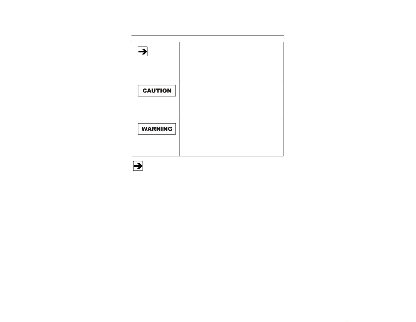
Notes, Cautions, and Warnings
Note: Denotes helpful information intended to
See the ETS-Lindgren Product Information Bulletin for safety,
regulatory, and other product marking information.
provide tips for better use of the product.
Caution: Denotes a hazard. Failure to follow
instructions could result in minor personal injury
and/or property damage. Included text gives proper
procedures.
Warning: Denotes a hazard. Failure to follow
instructions could result in SEVERE personal injury
and/or property damage. Included text gives proper
procedures.
| v
Page 6

This page intentionally left blank.
vi |
Page 7

1.0 Introduction
The ETS-Lindgren Model 3159 High-Power Biconical Antenna is a
broadband, linearly polarized biconical antenna with a 30 MHz to 100 MHz
frequency range. This antenna exhibits a wide beamwidth and is designed to
handle up to 10 kW input power for generating high electric field strength over a
large uniform area.
The standard
configuration for the
Model 3159 consists
of:
• Two open-end
biconical elements
• High-power balun
• Pedestal with
polarization control
The pedestal allows antenna height and tilt-angle to be easily adjusted, plus
features a wheeled base so that the antenna can be rolled out of the chamber
and stored when not in use. Slots below the base allow for easy transport with a
pallet jack or forklift. Horizontal and vertical polarization rotation is performed by
a toggle switch on the back. The air valve assembly for pneumatic polarization is
mounted onto the mast.
Introduction | 7
Page 8

Unlike the top hat, capacitive-loaded, log periodic dipole antenna normally used
in this frequency range, the phase center/source distance is the same for low and
high frequencies. This ensures high field strength at frequencies as low as
30 MHz. The design of the Model 3159 takes advantage of the wide beamwidth
feature of a biconical antenna. In addition, the optimized design provides
low VSWR and high radiation efficiency.
ETS-Lindgren Product Information Bulletin
See the ETS-Lindgren Product Information Bulletin included with your shipment
for the following:
• Warranty information
• Safety, regulatory, and other product marking information
• Steps to receive your shipment
• Steps to return a component for service
• ETS-Lindgren calibration service
• ETS-Lindgren contact information
8 | Introduction
Page 9

2.0 Maintenance
Before performing any maintenance,
follow the safety information in the
ETS-Lindgren Product Information
Bulletin included with your shipment.
WARRANT Y
• Check all screws periodically and tighten any that are loose.
• Check the air filters weekly; more often, as necessary. The air used to
feed the cylinder must be free of dirt and moisture. Never allow the air
filters to fill with water.
• Lubricate all O-rings and pistons at 18-month intervals to prevent
excessive wear. The air cylinder uses a special O-ring lubricant that
can be purchased from any seal or bearing store or from
ETS-Lindgren.
Maintenance of the Model 3159 is limited
to external components such as cables
or connectors.
If you have any questions concerning
maintenance, contact ETS-Lindgren
Customer Service.
Annual Calibration
See the Product Information Bulletin included with your shipment for information
on ETS-Lindgren calibration services.
Service Procedures
For the steps to return a system or system component to ETS-Lindgren for
service, see the Product Information Bulletin included with your shipment.
Maintenance | 9
Page 10

This page intentionally left blank.
10 | Maintenance
Page 11

3.0 Specifications
Electrical Specifications
Frequency: 30 MHz–100 MHz
Input Impedance: 50 Ω
VSWR:
Maximum RF Input Power: 10 kW
RF Connector: 1 5/8 in EIA flange
• Typical—2:1
• Maximum—4:1
Physical Specifications
MODEL 3159 ANTENNA
Length: 3 m (9.8 ft)
Diameter: 1.04 m (3.4 ft)
MODEL 3159 PEDESTAL
Length: 232.4 cm (91.5 in)
Width: 160 cm (63 in)
Total Height With Antenna: 365.7 cm (144 in)
Air Pressure Required: 80–120 PSI
Specifications | 11
Page 12

This page intentionally left blank.
12 | Specifications
Page 13

4.0 Mounting Instructions
Before connecting any components, follow the
safety information in the ETS-Lindgren
Product Information Bulletin included with your
shipment.
Do not cross thread connections or permanent damage could occur.
Mounting the Balun Unit
Due to the size of the Model 3159 biconical elements, you must mount
the balun unit onto the pedestal prior to attaching the elements.
1. With the RF connector facing the pedestal, align the two threaded
holes on the back of the balun with the holes on the boom.
2. Insert the hand mount knobs up and through the boom and into the
threaded holes of the balun.
3. Turn the knobs until the balun is firmly attached to the boom, and then
secure with nuts.
Mounting Instructions | 13
Page 14

Mounting the Biconical Elements
1. Once the balun
unit is securely
connected to the
boom, align the
threads on one
of the biconical
elements with
the receptacle on
the end of the
balun, and then
turn the biconical
element until it is
firmly seated in
the balun.
2. Tighten bolt to secure element.
3. Repeat steps for the remaining biconical element.
4. Once both elements are connected, attach the input cable to the connector
on the bottom of the balun.
14 | Mounting Instructions
Page 15

5.0 Operation
Before connecting any components or
operating the Model 3159, follow the safety
information in the ETS-Lindgren
Product Information Bulletin included with your
shipment.
The Model 3159 High-Power Biconical Antenna has a 4:1 Guanella balun for
matching the impedance to the amplifier. The balun maintains a low operating
temperature due to the efficient radiation pattern and high power design.
Model 3159 Pedestal
To prevent damage to the cables, you must
disconnect the RF cables from the Model 3159
before polarization or movement of the
boresight feature.
The Model 3159 pedestal has one air cylinder that controls the polarization
movement of the antenna. The switch on the back of the pedestal toggles
air control. Boresight is accomplished manually.
Electrical Field Distribution
The Model 3159 may be used for both horizontal and vertical polarization. It
exhibits a dipole-like radiation pattern; for example, a toroidal shape with an
omnidirectional pattern in the H-plane. In a low frequency range such as 30 MHz
(wavelength l = 10 m), the equipment under test (EUT) is in the near field of the
antenna, allowing the antenna to behave as a field generator.
Operation | 15
Page 16

Calibration Data
TYPICAL ANTENNA FACTOR AT 6M
CALCULATED FORWARD POWER AT 3.5M
A calculation was used to derive the forward power data once the six-meter
calibration was complete. The following equation was used to determine the
power required to generate the desired field strength at a given distance when
antenna factors are known:
20 log 10 [E desired (V/m)]
20 log10
20 log10
1 15
With this equation you can calculate the forward power needed to generate
100 V/m at a given distance. Following is the performance for the Model 3159 at
3.5m:
16 | Operation
Page 17

Operation | 17
Page 18

This page intentionally left blank.
18 | Operation
Page 19

Appendix A: Warranty
See the Product Information Bulletin included with your shipment for
the complete ETS-Lindgren warranty for your Model 3159.
DURATION OF WARRANTIES FOR MODEL 3159
All product warranties, except the warranty of title, and all remedies for warranty
failures are limited to two years.
Product Warranted Duration of Warranty Period
Model 3159 High-Power
Biconical Antenna
2 Years
Warranty | 19
 Loading...