

Page 1
Model 3150B
Dual-Stacked Log Periodic
Dipole Array Antenna
Assembly Manual
Page 2

ETS-Lindgren, Inc. reserves the right to make changes to any products herein to improve
Revision
Description
Date
A
Initial Release
October, 2012
functioning or design. Although the information in this document has been carefully reviewed and
is believed to be reliable, ETS-Lindgren does not assume any liability arising out of the
application or use of any product or circuit described herein; nor does it convey any license under
its patent rights nor the rights of others. All trademarks are the property of their respective
owners.
© Copyright 2012 by ETS-Lindgren, Inc. All Rights Reserved. No part of this document may
be copied by any means without written permission from ETS-Lindgren, Inc.
Trademarks used in this document: The ETS-Lindgren logo is a trademark of ETS-Lindgren, Inc.
Revision Record | MANUAL,3150B | Part #399335, Rev. A
ii |
Page 3

Table of Contents
Notes, Cautions, and Warnings ......................................................................... v
1.0 Introduction ................................ ................................ ................................ ... 7
Standard Configuration ....................................................................................................... 8
Optional 7-TR Tripod .......................................................................................................... 9
ETS-Lindgren Product Information Bulletin ........................................................................ 9
2.0 Maintenance ................................................................ ................................ 11
Replacement and Optional Parts ..................................................................................... 11
Service Procedures .......................................................................................................... 11
3.0 Specifications .............................................................................................. 13
Electrical Specifications .................................................................................................... 13
Physical Specifications ..................................................................................................... 13
4.0 Assembly Instructions ............................................................................... 15
Components to Assemble ................................................................................................ 15
Attach the Removable Elements ...................................................................................... 16
Overview of Steps ............................................................................................................ 17
Attach Two Boom Assemblies to Center Support Bar ..................................................... 18
Attach Feed Boom Assembly ........................................................................................... 20
Attach Remaining Two Boom Assemblies to Side Support Bars ..................................... 21
5.0 Mounting onto a 7-TR Tripod ..................................................................... 25
6.0 Disassembly Instructions .......................................................................... 29
7.0 Typical Data ................................................................................................. 31
Typical Antenna Factor and Gain ..................................................................................... 31
Typical Average Power Requirements ............................................................................. 32
Measured Power Requirements ................................................................................ 32
Horizontal Polarization, 2-M Distance ........................................................................ 33
Horizontal Polarization, 3-M Distance ........................................................................ 34
Vertical Polarization, 2-M Distance ............................................................................ 35
Vertical Polarization, 3-M Distance ............................................................................ 36
Typical VSWR................................................................................................................... 37
Typical Half Power Beamwidth ......................................................................................... 38
Typical Radiation Patterns ................................................................................................ 39
80 MHz—100 MHz ..................................................................................................... 39
200 MHz—300 MHz ................................................................................................... 40
| iii
Page 4

400 MHz—500 MHz ................................................................................................... 41
600 MHz—700 MHz ................................................................................................... 42
800 MHz—900 MHz ................................................................................................... 43
1000 MHz—2000 MHz ............................................................................................... 44
Appendix A: Warranty ...................................................................................... 45
iv |
Page 5
Notes, Cautions, and Warnings
Note: Denotes helpful information intended to provide tips for
better use of the product.
Caution: Denotes a hazard. Failure to follow instructions
could result in minor personal injury and/or property
damage. Included text gives proper procedures.
Warning: Denotes a hazard. Failure to follow instructions
could result in SEVERE personal injury and/or property
damage. Included text gives proper procedures.
See the ETS-Lindgren Product Information Bulletin for safety, regulatory, and other
product marking information.
| v
Page 6

This page intentionally left blank.
vi |
Page 7
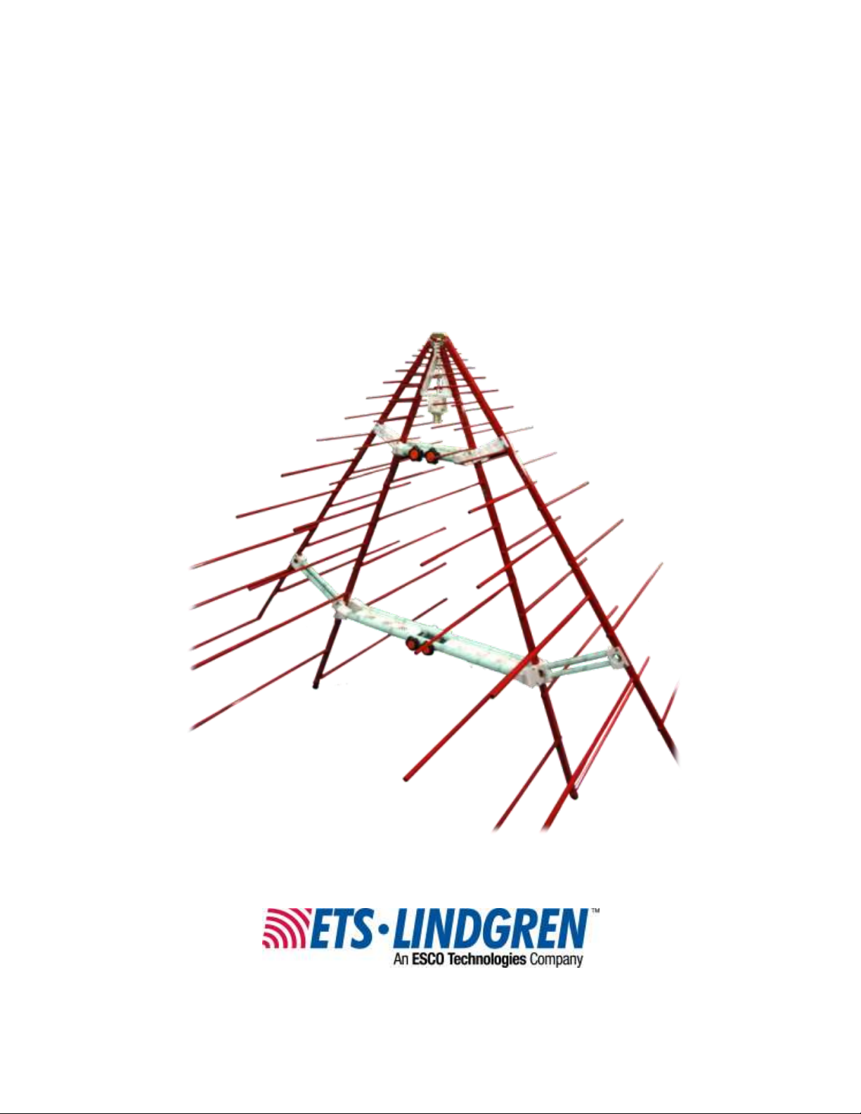
The ETS-Lindgren
Model 3150B Dual-Stacked
Log Periodic Dipole Array
(LPDA) Antenna is comprised
of two separate 100 ohm
LPDAs. The result is a 50 ohm
input impedance array when
assembled in parallel,
providing increased gain when
compared to a single LPDA.
Also, the VSWR is low so that
it provides excellent match
with the amplifier, resulting in
the generation of a high field
per input power.
1.0 Introduction
The Model 3150B is ideal in situations where high fields need to be generated.
Although the Model 3150B can be used as a receive antenna, the primary
application is for generating the high fields that are required in automotive EMC
applications per standards like ISO 11541-2, or for MIL-STD susceptibility
testing.
The frequency range covers 80 MHz to 1 GHz. The Model 3150B can generate
200 V/m with less than 1 kW of input power at a 1-m distance for the 100 MHz to
1 GHz range. When combined with ETS-Lindgren Model 3159 or Model 3158
High-Power Biconical Antennas, the 3150B becomes an integral part of the
ETS-Lindgren high severity level immunity solution.
The Model 3150B is fitted with a 7/16 coaxial connector. With this connector the
antenna can handle up to 5 kW of input power at 80 MHz and up to 3 kW at
1 GHz.
For easy horizontal and vertical polarization changes, the ETS-Lindgren 7-TR
Tripod is recommended; a special cross boom is required to use the
Model 3150B with the 7-TR. For information on the 7-TR and special
cross boom, see page 9. For mounting instructions, see Mounting onto a
7-TR Tripod on page 25.
Introduction | 7
Page 8
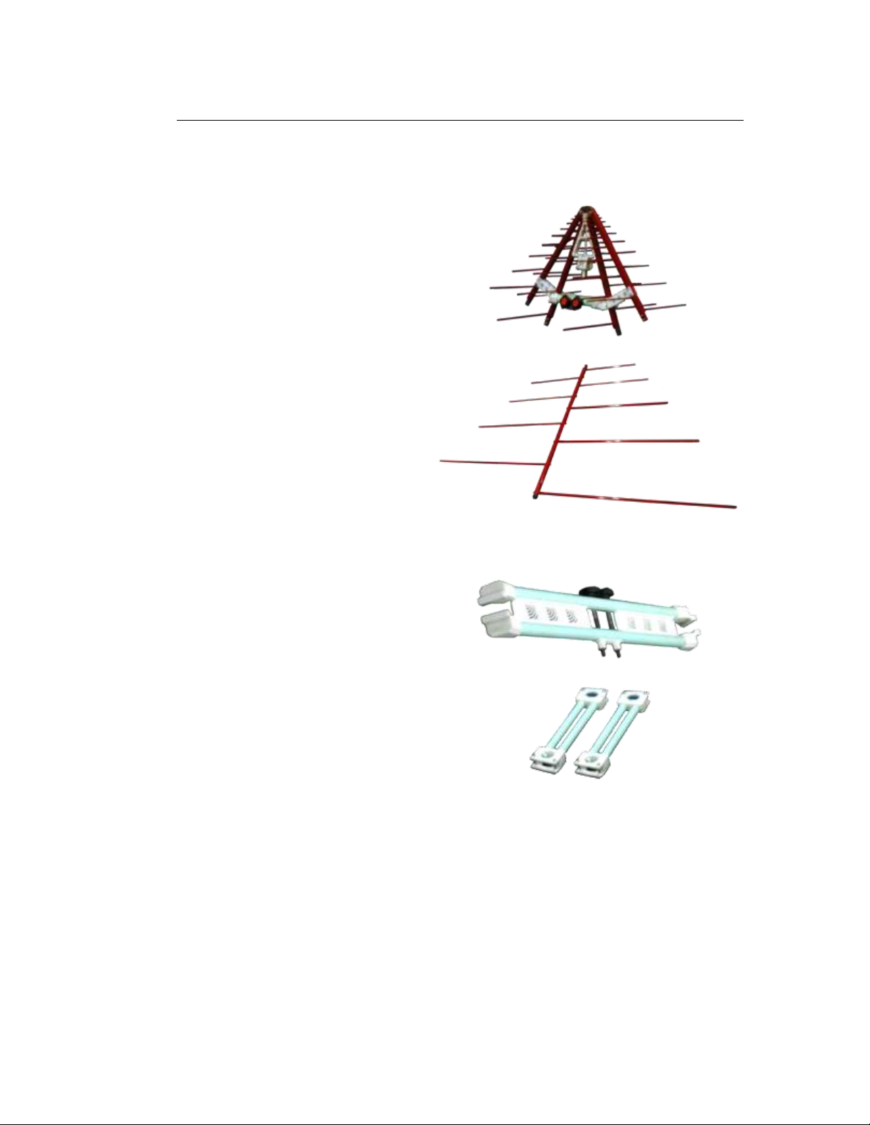
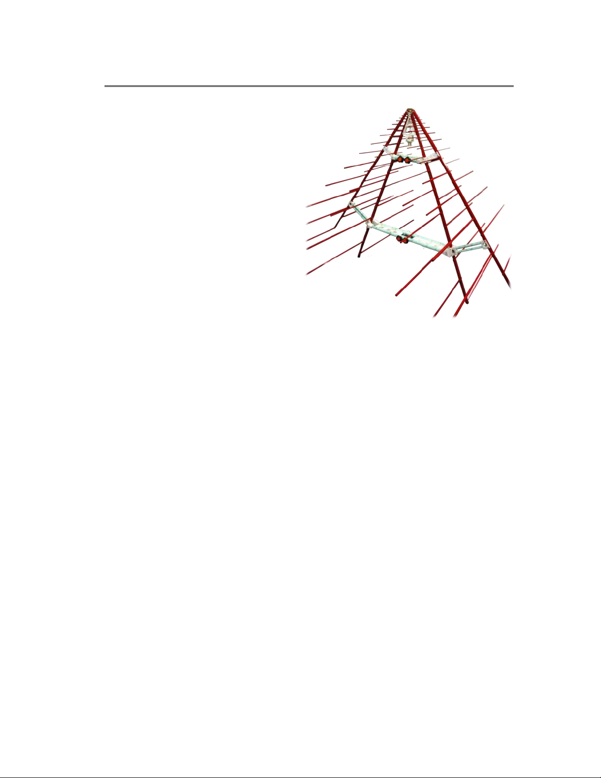
Feed Boom Assembly
Boom Assemblies (4)
The five longest elements
(the last five elements
from the bottom of each
boom assembly) are
removed for shipping. To
attach the removable
elements to the boom
assembly, see page 16.
(one boom assembly shown with
the five removable elements attached)
Center Support Bar
Side Support Bars (2)
Standard Configuration
The Model 3150B ships unassembled, and includes the following components to
be assembled, plus the necessary fasteners. For assembly steps, see page 15.
8 | Introduction
Page 9
The Model 3150B mounts to an ETS-Lindgren 7-TR Tripod using a special cross
boom (part# 118556). To order a 7-TR and cross boom, contact ETS-Lindgren
Sales.
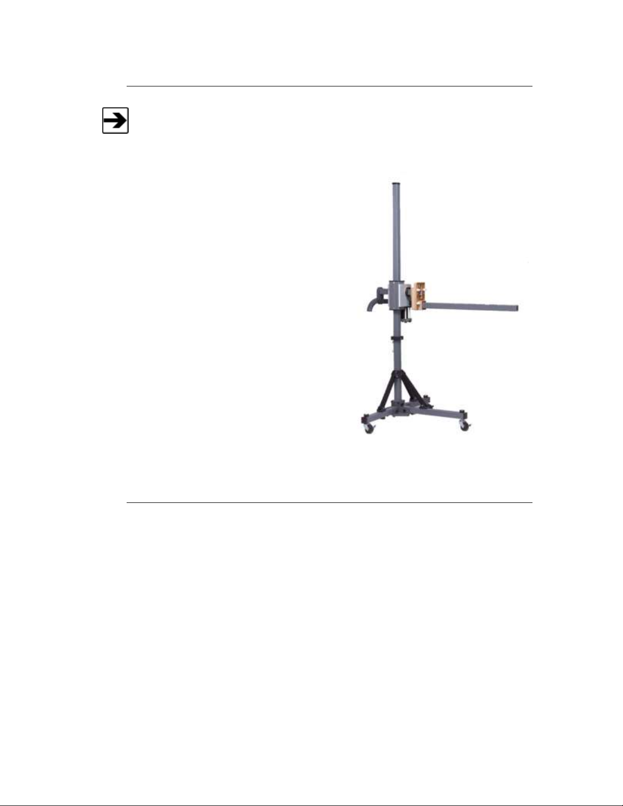
The ETS-Lindgren 7-TR Tripod is
constructed of PVC and fiberglass
components, providing increased
stability for physically large antennas.
The unique design allows for quick
assembly, disassembly, and
convenient storage. Allows several
different configurations, including
options for manual or pneumatic
polarization. Quick height adjustment
and locking wheels provide ease of
use during testing. Maximum height is
2.17 m (85.8 in), with a minimum
height of 0.8 m (31.8 in). This tripod
can support a 13.5 kg (30 lb) load.
7-TR shown with standard boom
Optional 7-TR Tripod
ETS-Lindgren Product Information Bulletin
See the ETS-Lindgren Product Information Bulletin included with your shipment
for the following:
Warranty information
Safety, regulatory, and other product marking information
Steps to receive your shipment
Steps to return a component for service
ETS Lindgren calibration service
ETS Lindgren contact information
Introduction | 9
Page 10

This page intentionally left blank.
10 | Introduction
Page 11
Before performing any maintenance, follow the safety
information in the ETS-Lindgren Product Information
Bulletin included with your shipment.
Maintenance of the Model 3150B is limited to external
components such as cables or connectors. If you have any
questions concerning maintenance, contact ETS-Lindgren
Customer Service.
If you have any questions concerning maintenance, contact
ETS Lindgren Customer Service.
ETS-Lindgren may substitute a similar part or new part number with the same
functionality for another part/part number. Contact ETS-Lindgren for questions
about part numbers and ordering parts.
Part Description
Part Number
7-TR Cross Boom for 3150B
118556
WARRANTY
2.0 Maintenance
Replacement and Optional Parts
Following are the part numbers for ordering replacement or optional parts for the
Model 3150B Dual Stacked Log Periodic Dipole Array (LPDA) Antenna.
Service Procedures
For the steps to return a system or system component to ETS-Lindgren for
service, see the Product Information Bulletin included with your shipment.
Maintenance | 11
Page 12

This page intentionally left blank.
12 | Maintenance
Page 13

Frequency Range:
80 MHz to 1 GHz
VSWR (Average):
2:1
Maximum Continuous Power:
5 kW at 80 MHz, 2.5 kW at 1 GHz
Peak Power:
7 kW at 80 MHz, 4 kW at 1 GHz
Impedance (Nominal):
50 Ω
Connector:
7/16 female
Height:
203.07 cm (79.95 in)
Width:
209.07 cm (82.31 in)
Depth:
150.44 cm (59.23 in)
Weight:
10.56 kg (23.28 lb)
3.0 Specifications
Electrical Specifications
Physical Specifications
Specifications | 13
Page 14

This page intentionally left blank.
14 | Specifications
Page 15

Before assembling or connecting any components, follow the
safety information in the ETS-Lindgren Product Information
Bulletin included with your shipment.
Take care when assembling the Model 3150B. Make sure the
antenna is on a stable surface at all times.
Assembly steps require assistance from one or more
crewmembers.
The four boom assemblies are identical and interchangeable.
You will require a Phillips screwdriver (not included) to assemble the Model 3150B.
4.0 Assembly Instructions
Components to Assemble
Assembly Instructions | 15
Page 16

Do not cross thread the connection or permanent damage to
the element or boom could occur.
Attach the Removable Elements
The five longest elements on each boom assembly (the last five from the bottom)
are removed for shipping, and should be re-attached during assembly inside the
chamber.
The elements and the location on the boom assembly where they attach are
marked with the numbers 1, 2, 3, 4, and 5.
1. Match the number 1 on the element with the number 1 on the boom.
The end of the element and the connector on the boom are threaded;
rotate the element into the connector, and then hand tighten.
2. Repeat step 1 for elements marked 2, 3, 4, and 5, attaching them to the
corresponding locations on the boom marked 2, 3, 4, and 5.
3. Repeat step 1 and step 2 for each boom assembly.
16 | Assembly Instructions
Page 17

Before you begin, see page 16 to attach the removable elements to each
boom assembly.
Overview of Steps
Assembly Instructions | 17
Page 18

Before you begin, see page 16 to attach the removable elements to each
boom assembly.
Attach Two Boom Assemblies to Center Support Bar
18 | Assembly Instructions
Page 19

Assembly Instructions | 19
Page 20

Attach Feed Boom Assembly
20 | Assembly Instructions
Page 21

Attach Remaining Two Boom Assemblies to Side Support Bars
Assembly Instructions | 21
Page 22

22 | Assembly Instructions
Page 23

Assembly Instructions | 23
Page 24

This page intentionally left blank.
24 | Assembly Instructions
Page 25

The Model 3150B mounts to an ETS-Lindgren 7-TR Tripod using a special
cross boom (part# 118556). Install the 118556 cross boom prior to mounting the
Model 3150B onto the 7-TR.
5.0 Mounting onto a 7-TR Tripod
Mounting onto a 7-TR Tripod | 25
Page 26

26 | Mounting onto a 7-TR Tripod
Page 27

Mounting onto a 7-TR Tripod | 27
Page 28

This page intentionally left blank.
28 | Mounting onto a 7-TR Tripod
Page 29

Before disconnecting any components, follow the safety
information in the ETS-Lindgren Product Information Bulletin
included with your shipment.
Place the Model 3150B on a stable surface before disassembling.
As you remove parts, place them in a safe location. Store
disassembled components in secure, protective location. Retain
all fasteners.
See the corresponding step in Assembly Instructions on page 15 for detailed
information about how each component is attached.
6.0 Disassembly Instructions
Disassembly Instructions | 29
Page 30

This page intentionally left blank.
30 | Disassembly Instructions
Page 31

7.0 Typical Data
Typical Antenna Factor and Gain
Typical Data | 31
Page 32

Typical Average Power Requirements
MEASURED POWER REQUIREMENTS
32 | Typical Data
Page 33

HORIZONTAL POLARIZATION, 2-M DISTANCE
Typical Data | 33
Page 34

HORIZONTAL POLARIZATION, 3-M DISTANCE
34 | Typical Data
Page 35

VERTICAL POLARIZATION, 2-M DISTANCE
Typical Data | 35
Page 36

VERTICAL POLARIZATION, 3-M DISTANCE
36 | Typical Data
Page 37

The typical VSWR for the Model 3150B is less than 2:1 from 80 MHz to 400 MHz.
Above that frequency the average VSWR is 2:1.
Typical VSWR
Typical Data | 37
Page 38

Typical Half Power Beamwidth
38 | Typical Data
Page 39

Typical Radiation Patterns
80 MHZ—100 MHZ
Typical Data | 39
Page 40

200 MHZ—300 MHZ
40 | Typical Data
Page 41

400 MHZ—500 MHZ
Typical Data | 41
Page 42

600 MHZ—700 MHZ
42 | Typical Data
Page 43

800 MHZ—900 MHZ
Typical Data | 43
Page 44

1000 MHZ—2000 MHZ
44 | Typical Data
Page 45

See the Product Information Bulletin included with your shipment for the complete
ETS-Lindgren warranty for your Model 3150B.
Product Warranted
Duration of Warranty Period
Model 3150B Log Periodic
Array Antenna
2 Years
Appendix A: Warranty
DURATION OF WARRANTIES FOR MODEL 3150B
All product warranties, except the warranty of title, and all remedies for warranty
failures are limited to two years.
Warranty | 45
 Loading...