

Page 1
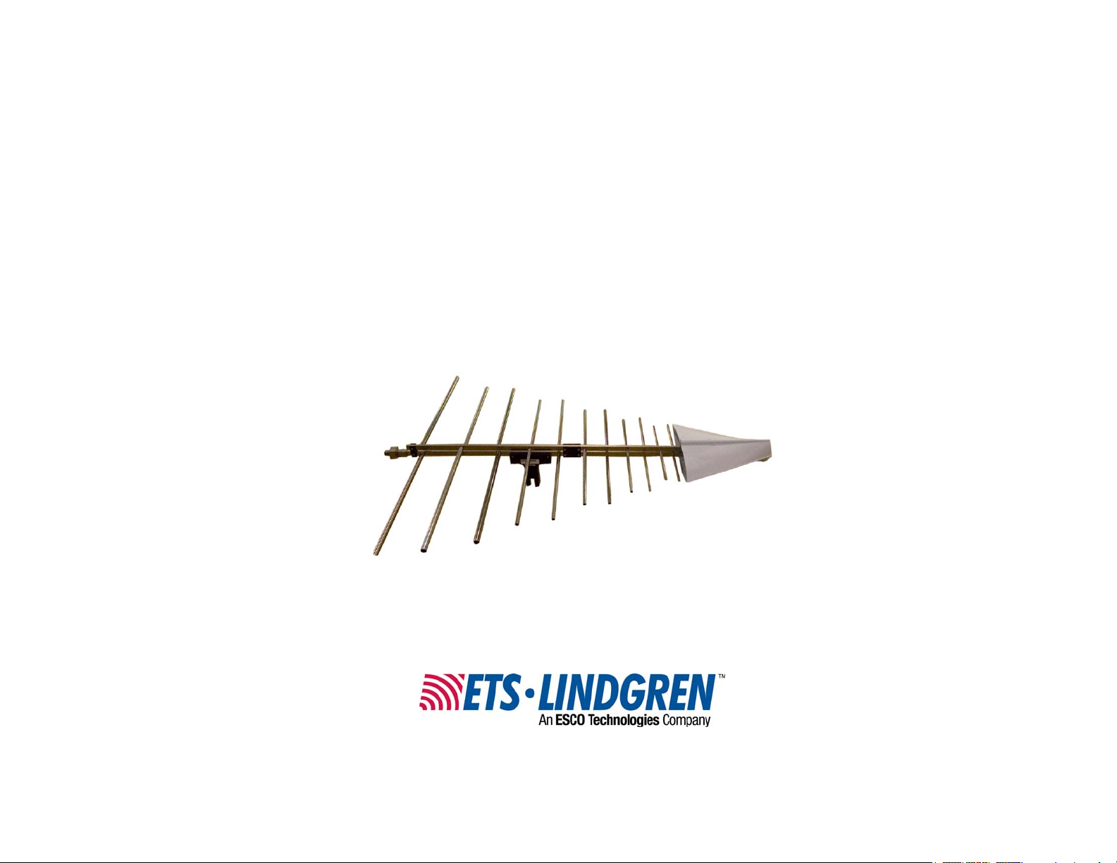
Model 3147
Log Periodic
Dipole Antenna
User Manual
Page 2

ETS-Lindgren L.P. reserves the right to make changes to any product described
herein in order to improve function, design, or for any other reason. Nothing
contained herein shall constitute ETS-Lindgren L.P. assuming any liability
whatsoever arising out of the application or use of any product or circuit
described herein. ETS-Lindgren L.P. does not convey any license under its
patent rights or the rights of others.
© Copyright 1999–2010 by ETS-Lindgren L.P. All Rights Reserved. No part
of this document may be copied by any means without written permission
from ETS-Lindgren L.P.
Trademarks used in this document: The ETS-Lindgren logo is a trademark of
ETS-Lindgren L.P.
Revision Record
MANUAL 3147 LOG PERIODIC ANTENNA | Part #399160, Rev. F
Revision Description Date
A Initial Release January, 1999
B Updated content/branding October, 2002
C Edited content, rebranding changes June, 2008
D Updated photos April, 2009
E Added Mounting Instructions March, 2010
F Corrected error in Power
Requirements table; updated part
numbers in Mounting Instructions
ii |
November, 2010
Page 3

Table of Contents
Notes, Cautions, and Warnings ................................................ v
1.0 Introduction .......................................................................... 7
Regarding Calibration of Log Periodic Dipole Antennas ................................ 8
ETS-Lindgren Product Information Bulletin ................................................... 9
2.0 Maintenance ....................................................................... 11
Maintenance Recommendations ................................................................. 11
Annual Calibration ....................................................................................... 11
Service Procedures ..................................................................................... 11
3.0 Specifications ..................................................................... 13
Electrical Specifications ............................................................................... 13
Physical Specifications ................................................................................ 13
4.0 Mounting Instructions ....................................................... 15
Using Included Mounting Adapters .............................................................. 15
Additional Mounting Options ........................................................................ 17
4-TR Mounting Options ................................................................................ 17
7-TR and Mast Mounting Options ................................................................ 18
2x2 Boom Mounting Options ....................................................................... 19
5.0 Operation ............................................................................ 21
Model 3147 Assembly Instructions .............................................................. 21
Model 3147 Use ........................................................................................... 21
6.0 Typical Data ........................................................................ 23
Typical VSWR for Model 3147 ..................................................................... 23
Typical Antenna Factor and Gain for Model 3147 ....................................... 24
Beamwidth for Horizontally and Vertically Polarized Model 3147................ 26
Front-to-Back Ratio for Model 3147 ............................................................. 28
Cable Attenuation (dB) at 20°C for 6-M Cable ............................................. 29
Typical Antenna Pattern for 200 MHz and 300 MHz ................................... 30
7.0 Radiated Emissions Measurement .................................. 31
Conversion Factors ...................................................................................... 32
8.0 Power Requirements ......................................................... 35
Power Requirements Table ......................................................................... 36
| iii
Page 4

80 Watts Continuous Power ........................................................................ 36
40 Watts Continuous Power ........................................................................ 38
Appendix A: Typical Antenna Patterns ................................. 41
400 MHz ...................................................................................................... 41
500 MHz ...................................................................................................... 41
600 MHz ...................................................................................................... 42
700 MHz ...................................................................................................... 42
800 MHz ...................................................................................................... 43
900 MHz ...................................................................................................... 43
1.0 GHz ........................................................................................................ 44
1.5 GHz ........................................................................................................ 44
2.0 GHz ........................................................................................................ 45
2.5 GHz ........................................................................................................ 45
3.0 GHz ........................................................................................................ 46
3.5 GHz ........................................................................................................ 46
4.0 GHz ........................................................................................................ 47
4.5 GHz ........................................................................................................ 47
5.0 GHz ........................................................................................................ 48
Appendix B: Warranty ............................................................. 49
iv |
Page 5
Notes, Cautions, and Warnings
Note: Denotes helpful information intended to
See the ETS-Lindgren Product Information Bulletin for safety,
regulatory, and other product marking information.
provide tips for better use of the product.
Caution: Denotes a hazard. Failure to follow
instructions could result in minor personal injury
and/or property damage. Included text gives proper
procedures.
Warning: Denotes a hazard. Failure to follow
instructions could result in SEVERE personal injury
and/or property damage. Included text gives proper
procedures.
| v
Page 6

This page intentionally left blank.
vi |
Page 7
1.0 Introduction
The ETS-Lindgren
Model 3147 Log Periodic
Dipole Antenna is a
linearly-polarized broadband
antenna designed to operate
over the frequency range of
200 MHz to 5 GHz. The
antenna was designed with
the latest revision to Part 15
of FCC Rules and
Regulations in mind. See
page 13 for specifications.
The Model 3147 is constructed from 30 elements mounted on two 6.35-mm by
12.7-mm booms. The choice of scaling factors, the various diameters of each
element, and the center-to-center spacing of the booms yield excellent VSWR
characteristics throughout the operating frequency range (see VSWR on
page 23). The precise design of the feed and the positioning of the elements on
the boom yield an optimum phase relationship. This causes the active region, at
any given frequency, to propagate RF energy towards the smaller elements,
leaving the elements behind it electrically dead.
The constant gain of the Model 3147 yields an antenna factor which varies
linearly with frequency, as shown in Typical Data on page 23. The variation is
smooth; therefore, accurate interpolation of performance between specified
frequency points is simple.
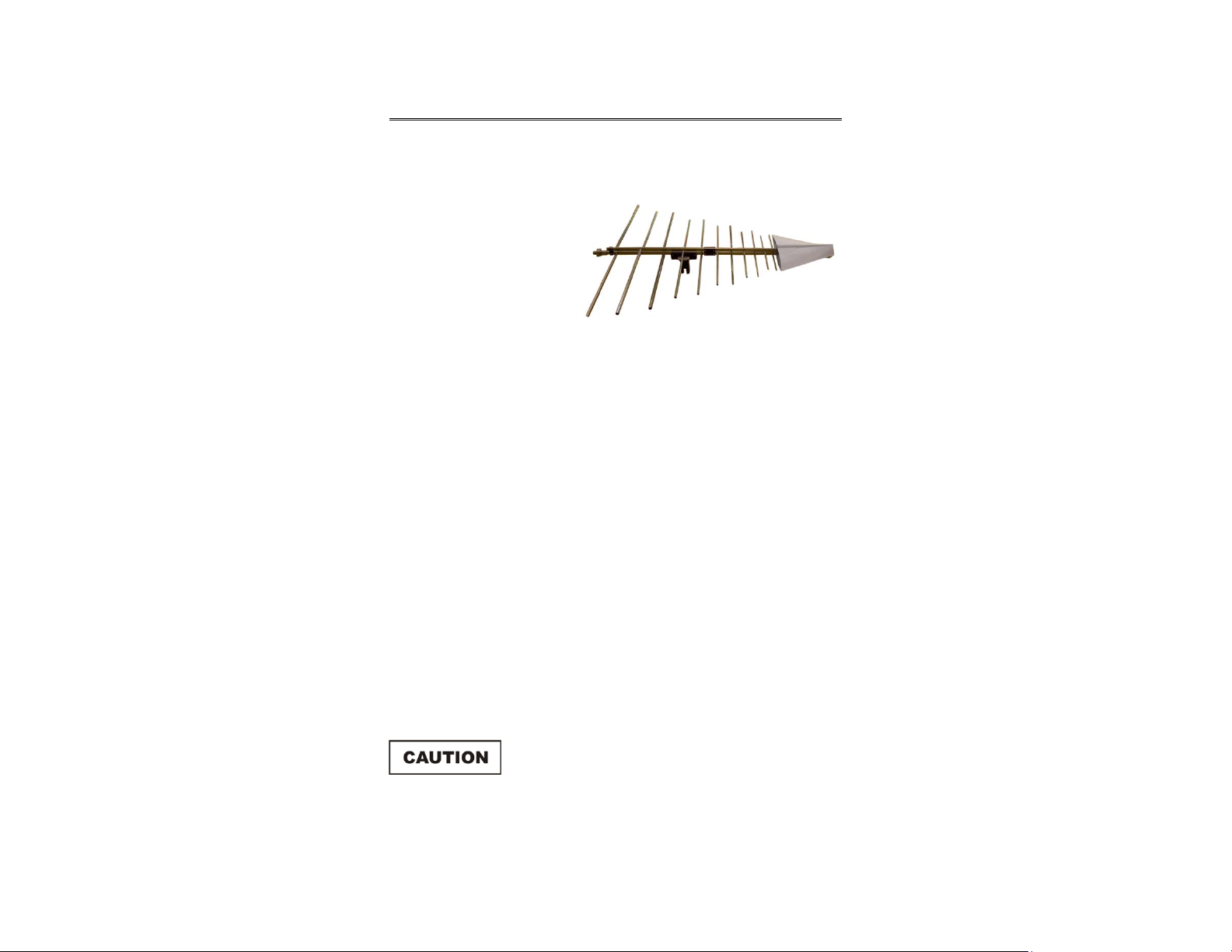
Due to the relatively high upper frequency limit, the small elements on the
Model 3147 are very thin. The antenna is equipped with an integral, low
dielectric-constant radome to protect the elements from possible damage.
Do not disassemble or drop the antenna or the
thin elements may be damaged.
Introduction | 7
Page 8

Because the radome is almost RF-invisible, it has very little effect on the
performance of the Model 3147 (see VSWR on page 23).
The base of the Model 3147 accepts an ETS-Lindgren or other tripod mount with
1/4–20 threads. Additionally, the antenna is shipped with a support rod. A variety
of mounting options are available for the Model 3147. For information, see
Mounting Instructions on page 15.
Regarding Calibration of Log Periodic Dipole Antennas
To meet the requirements of two different specifications, this log periodic dipole
antenna was calibrated at two different spacings.
• SAE ARP 958 (Society of Automotive Engineers, Aerospace
Recommended Practice) requires an antenna spacing of one meter,
measured tip to tip.
• ANSI 63.5 requires a spacing of three and ten meters measured from
the projection onto the ground plane of the midpoint of the longitudinal
axis of the antenna.
The ARP and the ANSI requirements disagree because these standards were
written for different purposes. Therefore, when calibrating the log periodic array
antennas per ARP 958, ETS-Lindgren measures from tip to tip and sets the
spacing to one meter. When calibrating the log periodic array antennas per
ANSI C63.5, ETS-Lindgren measures from the midpoint to the midpoint of the log
periodic antennas for 3-meter and 10-meter calibrations.
It is important in compliance demonstration testing to measure the
spacing from the antenna to the Equipment Under Test (EUT) as it
was measured when calibration was performed.
For additional information, contact ETS-Lindgren.
8 | Introduction
Page 9

ETS-Lindgren Product Information Bulletin
See the ETS-Lindgren Product Information Bulletin included with your shipment
for the following:
• Warranty information
• Safety, regulatory, and other product marking information
• Steps to receive your shipment
• Steps to return a component for service
• ETS-Lindgren calibration service
• ETS-Lindgren contact information
Introduction | 9
Page 10

This page intentionally left blank.
10 | Introduction
Page 11

2.0 Maintenance
Before performing any maintenance, follow the
safety information in the ETS-Lindgren
Product Information Bulletin included with your
shipment.
Maintenance of the Model 3147 Log Periodic Dipole Antenna is limited to
external components such as cables or connectors. If you have any questions
concerning maintenance, contact ETS-Lindgren Customer Service.
Maintenance Recommendations
If the Model 3147 is used outdoors, periodic removal of the antenna cable
connection and cleaning of any corrosion may be needed to maintain accuracy of
the measurements. An inspection to determine the need for cleaning should be
made at least every six months. More frequent inspection may be needed
depending on the atmosphere and the environment in which the antenna is used.
Annual Calibration
See the Product Information Bulletin included with your shipment for information
on ETS-Lindgren calibration services.
Service Procedures
For the steps to return a system or system component to ETS-Lindgren for
service, see the Product Information Bulletin included with your shipment.
Maintenance | 11
Page 12

This page intentionally left blank.
12 | Maintenance
Page 13

3.0 Specifications
Electrical Specifications
Frequency Range: 200 MHz–5 GHz
VSWR: Average: 1.25:1
Impedance: 50 Ω
Maximum: 1.7:1
Maximum Continuous
Input Power:
Maximum Peak Input Power: 100 W at 1 GHz
Connector: Precision N female
80 W at 1 GHz
40 W at 5 GHz
50 W at 5 GHz
Physical Specifications
Height: 7.62 cm
3.0 in
Width: 88 cm
34.65 in
Depth: 97 cm
38.19 in
Weight: 4.25 kg
9.36 lb
Specifications | 13
Page 14

This page intentionally left blank.
14 | Specifications
Page 15
4.0 Mounting Instructions
Before connecting any components, follow the
safety information in the ETS-Lindgren
Product Information Bulletin included with your
shipment.
The Model 3147 is a precision measurement
device. Handle with care.
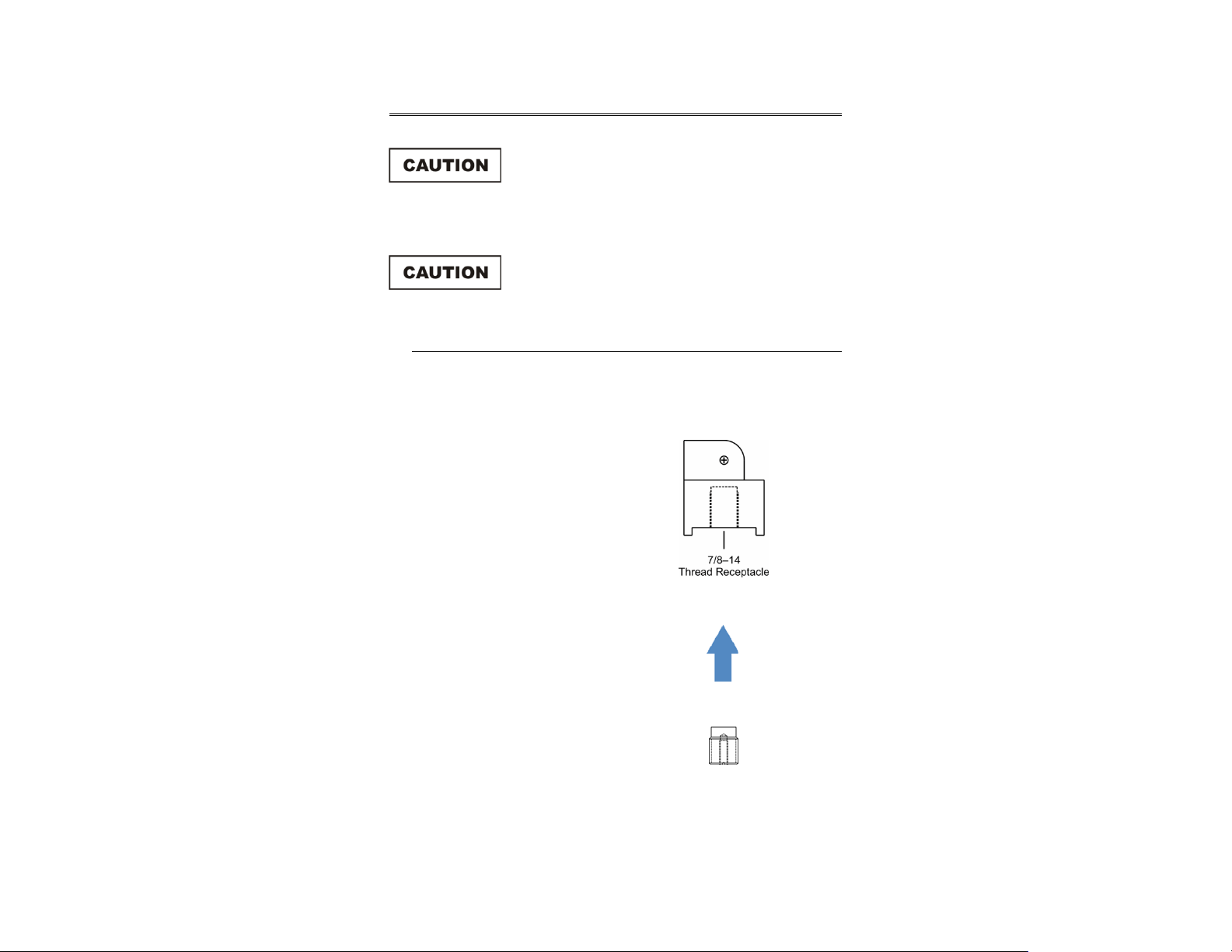
Using Included Mounting Adapters
The Model 3147 Log Periodic Dipole Antenna ships with these mounting
adapters:
• 100989 Polarizing Mounting
Adapter with 7/8–14 thread
receptacle
If you need to convert the polarizing
adapter to a 1/4–20 receptacle,
insert the 1/4–20 thread insert into
the polarizing adapter
• 105861 1/4–20 Thread Insert
Mounting Instructions | 15
Page 16

To attach the included adapters to the Model 3147:
1. If required, insert the 1/4–20 thread insert into the polarizing adapter.
2. Remove the mounting knob from the mounting bracket on the antenna.
3. Slide the polarizing adapter into the mounting bracket by placing the
polarizing adapter placed between the shoulders of the mounting
bracket.
16 | Mounting Instructions
Page 17

4. Thread the mounting knob through the mounting bracket, then through
the polarizing adapter, and finally through the hex nut.
Do not cross thread or permanent damage to the adapter could occur.
5. Tighten the mounting knob to secure the antenna.
6. Attach the polarizing adapter and antenna to tripod or tower, as
required.
Additional Mounting Options
4-TR MOUNTING OPTIONS
Following are additional options for mounting the Model 3147 onto an
ETS-Lindgren 4-TR tripod. Contact the ETS-Lindgren Sales Department for
information on ordering optional mounting hardware.
Mounting Instructions | 17
Page 18

7-TR AND MAST MOUNTING OPTIONS
Following are options for mounting the Model 3147 onto an ETS-Lindgren 7-TR
Tripod or mast. Contact the ETS-Lindgren Sales Department for information on
ordering optional mounting hardware.
Mast refers to 2070 Series, 2075, and 2175 Antenna Towers.
7-TR refers to 109042, 108983, and 108507 booms:
• 109042 boom—Straight boom; for general antenna mounting on a
7-TR
• 108983 boom—Offset boom; for general antenna mounting on a
7-TR with pneumatic or manual polarization; can also be used to
mount stinger-type antennas
18 | Mounting Instructions
Page 19

2X2 BOOM MOUNTING OPTIONS
Following are additional options for mounting the Model 3147 onto a 2x2 boom.
Contact the ETS-Lindgren Sales Department for information on ordering optional
mounting hardware.
2x2 boom refers to a typical 2-inch by 2-inch boom.
Mounting Instructions | 19
Page 20

This page intentionally left blank.
20 | Mounting Instructions
Page 21

5.0 Operation
Before connecting any components, follow the
safety information in the ETS-Lindgren
Product Information Bulletin included with your
shipment.
Model 3147 Assembly Instructions
A variety of mounting options are available for the Model 3147. For
information, see Mounting Instructions on page 15.
To attach the support rod to the base of the Model 3147 Log Periodic Dipole
Antenna:
1. Remove the clamping screw from the mount on the antenna.
2. Insert the support rod.
3. Replace the screw.
4. Place the support rod and base onto a tripod, and then tighten the
1/4–20 screw in the bottom of the base.
5. Remove the red connector cover from the precision N connector.
6. Attach a cable to the precision N connector and to the input of a
measuring device.
Model 3147 Use
The Model 3147 may be used for either reception or transmission of
electromagnetic energy. The primary design goal is the efficient reception of
signals from 200 MHz to 5 GHz for electromagnetic compatibility testing to
commercial standards such as CFR 47 Part 15 of the FCC Rules and
Regulations. Typical performance data is provided beginning on page 23 to
assist with use. Methods of use for radiated emissions measurement are
described on page 31.
Operation | 21
Page 22

This page intentionally left blank.
22 | Operation
Page 23

6.0 Typical Data
Following are typical measurements for the Model 3147 Log Periodic Dipole
Antenna.
Typical VSWR for Model 3147
This is a plot of the VSWR showing the antenna with and without a
radome. The effect of the radome on the electromagnetic performance
of the antenna is minimal.
Typical Data | 23
Page 24

Typical Antenna Factor and Gain for Model 3147
24 | Typical Data
Page 25

The antenna factor of the Model 3147 (triangles) measured at the distance of
three meters as per ANSI C63.5. The standard states that the spacing R
between log-periodic array antennas is measured from the projection onto the
ground plane of the midpoint of the longitudinal axis of each antenna. This
midpoint has been marked on the radome and labeled Reference Point
Per ANSI C63.5. The line shown in the figure is a linear fit to the antenna factor
data. The second curve shows the gain of the antenna as computed from the
antenna factor by:
G(dB) = 20 log(F
) – 29.79 – AF
MHz
dB(m-1)
Typical Data | 25
Page 26

Beamwidth for Horizontally and Vertically Polarized Model 3147
The beamwidth charts show the 3-dB and 10-dB power beamwidth as
determined from the antenna patterns taken for both horizontal and
vertical polarizations.
26 | Typical Data
Page 27

Typical Data | 27
Page 28

Front-to-Back Ratio for Model 3147
The front-to-back ratio is representative of how well the antenna
propagates energy in the end fire direction. The measurement is made
by first positioning two identical Model 3147 antennas face-to-face at a
2-meter height and a 3-meter distance. A signal is transmitted through
one antenna and received with the other. The transmitting antenna is
then rotated 180° in azimuth so that the back is pointed towards the
receiving antenna. The difference between the two measurements is
taken as the front-to-back ratio.
28 | Typical Data
Page 29

Cable Attenuation (dB) at 20°C for 6-M Cable
Typical Data | 29
Page 30

Typical Antenna Pattern for 200 MHz and 300 MHz
This shows a sample antenna pattern taken at selected frequencies of 200 MHz
and 300 MHz. Additional antenna patterns are located in Appendix A on page 41.
These patterns were measured indoors using a separation distance of 1 meter to
1.5 meters between the transmit antenna and the receive antenna.
The antenna patterns in Appendix A and the beamwidths on page 26 are useful
in determining the size of the Equipment Under Test (EUT) that can be measured
with the Model 3147 at a specified distance.
30 | Typical Data
Page 31

7.0 Radiated Emissions Measurement
Before connecting any components, follow the
safety information in the ETS-Lindgren
Product Information Bulletin included with your
shipment.
Ambient field strength values are measured as follows:
1. Install the antenna where measured field strength values are desired.
2. Select the desired orientation of the antenna, both boresite direction
and polarization.
3. Connect the antenna output connector to the input of the receiving
system using a coaxial cable. These antennas are calibrated for
receiving systems having 50-Ω input impedance. Other values of
receiving system input impedance will require correction for the
differences in input impedance.
4. Select the desired frequency of measurement on the receiving system.
5. Measure the RF voltage, V
receiving system. The units of the measurement should be in dB
referenced to 1 microvolt, dB(µV). If the units of measurement as
displayed by the receiver are not dB(µV), for example, in millivolts, they
should be converted to microvolts and then converted to dB(µV) by:
Va = 20 x log
Va = 20 x log
6. To determine the field strength at the frequency of the observation, add
the voltage reading from the receiving system in dB(µV) to the value
given by the antenna factor chart at that frequency in dB (m
RF Voltage, dB(µV) + Antenna Factor dB (m
Ea = Va + AF
Radiated Emissions Measurement | 31
, referenced to the input port of the
a
(RF voltage in microvolts)
10
10vd
Field Strength dB (µV/m)
-1
):
-1
) =
Page 32

If a long coaxial cable is used between the antenna and the receiving device, or
the frequency of the observation is more than several tens of MHz, the losses in
the coaxial cable, Ae, must be included in the computation. In this case the
computation is:
RF Voltage, dB(µV) + Cable Loss, dB + Antenna Factor, dB (m
Field Strength dB (µV/m)
Ea = Va + AF + Ae
Conversion Factors
Following are some useful conversion formulas.
dBm = dB(µV) – 107
dB(mW/m2) = dB(µV/m) – 115.8
dB(µV/m) = dB(µV) + AF
dB(µV/m) – 120
V/m = 10
20
-1
) =
dB(µA/m) = dB(µV/m) – 51.5
dB(µA/m) – 120
A/m = 10
20
dB(W/m2) = 10 log(V/m A/m)
dB(mW/m2) = dB(W/m2) + 30
dB(pT) = dB(µA/m) + 2.0
The constants that appear in the above equations are obtained as follows:
In the first equation, the power is related to the voltage via the system impedance
as:
2
V
P =
R
32 | Radiated Emissions Measurement
Page 33

In a 50-Ω system, the above equation becomes:
10 log10P = 20 log10 V – 10 log10(50)
Converting from dB to dBm for power and from dB(V) to dB(µV) for voltage, the
added constant becomes:
30 – 120 – 10 log10(50) = –107
The constant in the second equation is obtained by considering the pointing
vector which relates the power density in (W/m
(V/m) by:
2
|E|
2
) to the electric field density in
P =
η
Where η is the free space characteristic impedance equal to 120π Ω.
Transforming the previous equation to decibels and using the appropriate
conversion factors to convert dB(W/m
dB(V/m) to dB(µV/m) for the electric field, the constant becomes:
2) to dB(mW/m2) for power density and
30 – 120 – 10 log10(120π) = –115.8
For the constant in the fifth equation, the magnetic field density is related to the
electric field density via the characteristic impedance of free space. When the
transformation is made to decibels, the constant becomes:
20 log10(120π) = 51.5
In the last equation, the magnetic flux density B in (T) is related to the magnetic
field density H in (A/m) the permeability of the medium in (H/m). For free space
the permeability is µo = 4π10
to (µA/M) and taking the log, the constant becomes:
-7
H/m. Converting from (T) to (pT) and from (A/m)
240 – 120 + 20 log10(4πx10-7) = 2.0
Radiated Emissions Measurement | 33
Page 34

This page intentionally left blank.
34 | Radiated Emissions Measurement
Page 35

8.0 Power Requirements
The Model 3147 Log Periodic Dipole Antenna may also be used as a transmitting
antenna. The power input requirements for a desired electric field strength level
are provided in the Power Requirements table on page 36. The power is
computed according to the transmission equation:
2
(field strength)
Power transmitted =
2R2
|E|
Pt =
In the Power Requirements table on page 36, R is 3 meters. It is measured from
the center of the antenna as per ANSI C63.5. The power limitation is 80 Watts
maximum continuous power for frequencies below 1 GHz and 40 Watts
maximum continuous power above 1 GHz. An asterisk indicates where the power
required to generate a certain field level exceeded the maximum continuous
power rating. As an example, to generate a 20 V/m electric field at 1 GHz, the
measured antenna factor is 23.2 dB(m
30 g
-1
). The gain in dB is computed using:
(distance in meters) 2
(30 x Numeric Gain)
G(dB) = 20 log10(F
G(dB) = 20 log
Converting this value to obtain numeric gain:
0.7
g = 10
Applying the formula for the power transmitted:
|E|
Pt =
10
= 5.0
2R2
30 g 30(5)
Power Requirements | 35
) – 29.79 – AF
MHz
(1000) – 29.79 – 23.2 = 7.0
(202)(32)
=
= 24
Page 36

Power Requirements Table
Power requirements for a given field strength computed using typical antenna
calibration factors at 3-meter spacing.
80 WATTS CONTINUOUS POWER
Freq
(MHz)
200 11.7 4.5 2.8 0.106 10.6 42.6
225 12.8 4.5 2.8 0.106 10.6 42.6
250 12.9 5.2 3.3 0.091 9.1 36.2
275 13.5 5.5 3.5 0.085 8.5 33.8
300 13.8 6.0 4.0 0.075 7.5 30.1
325 14.1 6.3 4.3 0.070 7.0 28.1
350 14.9 6.2 4.2 0.072 7.2 28.8
375 15.8 5.9 3.9 0.077 7.7 30.8
400 16.4 5.8 3.8 0.079 7.9 31.6
425 17.4 5.3 3.4 0.089 8.8 35.4
450 17.8 5.5 3.5 0.085 8.5 33.8
475 18.1 5.7 3.7 0.081 8.1 32.3
500 18.2 6.0 4.0 0.075 7.5 30.1
AF
Gain
(dB)
Gain
(num)
Field Strength (E)
1 V/m 10 V/m 20 V/m
525 18.5 6.1 4.1 0.074 7.4 29.4
550 18.9 6.2 4.2 0.072 7.2 28.8
575 19.0 6.4 4.4 0.069 6.9 27.5
600 19.2 6.5 4.5 0.067 6.7 26.9
36 | Power Requirements
Page 37

Freq
(MHz)
625 19.6 6.5 4.5 0.067 6.7 26.9
650 20.2 6.3 4.3 0.070 7.0 28.1
675 20.3 6.5 4.5 0.067 6.7 26.9
700 21.2 5.9 3.9 0.077 7.7 30.8
725 21.6 5.9 3.9 0.077 7.7 30.8
750 21.9 5.8 3.8 0.079 7.9 31.6
775 21.4 6.6 4.6 0.066 6.6 26.3
800 21.1 7.2 5.2 0.057 5.7 22.9
825 21.6 6.9 4.9 0.061 6.1 24.5
850 22.1 6.7 4.7 0.064 6.4 25.6
875 22.8 6.3 4.3 0.070 7.0 28.1
900 23.9 5.4 3.5 0.087 8.6 34.6
925 23.5 6.1 4.1 0.074 7.4 29.4
AF
Gain
(dB)
Gain
(num)
Field Strength (E)
1 V/m 10 V/m 20 V/m
950 23.6 6.2 4.2 0.072 7.2 28.8
975 23.3 6.7 4.7 0.064 6.4 25.6
1000 23.2 7.0 5.0 0.060 6.0 23.9
Power Requirements | 37
Page 38

40 WATTS CONTINUOUS POWER
Freq
(MHz)
1000 23.2 7.0 5.0 0.060 6.0 23.9
1100 23.4 7.6 5.8 0.052 5.2 20.8
1200 23.8 8.1 6.5 0.046 4.6 18.6
1300 24.1 8.4 6.9 0.043 4.3 17.3
1400 25.6 7.5 5.6 0.053 5.3 21.3
1500 26.2 7.6 5.8 0.052 5.2 20.8
1600 26.7 7.6 5.8 0.052 5.2 20.8
1700 27.6 7.3 5.4 0.056 5.6 22.3
1800 28.5 6.9 4.9 0.061 6.1 24.5
1900 28.5 7.3 5.4 0.056 5.6 22.3
2000 29.1 7.2 5.2 0.057 5.7 22.9
2100 29.8 6.9 4.9 0.061 6.1 24.5
2200 30.0 7.1 5.1 0.058 5.8 23.4
AF
Gain
(dB)
Gain
(num)
Field Strength (E)
1 V/m 10 V/m 20 V/m
2300 30.5 7.0 5.0 0.060 6.0 23.9
2400 31.4 6.5 4.5 0.067 6.7 26.9
2500 32.2 6.0 4.0 0.075 7.5 30.1
2600 32.8 5.7 3.7 0.081 8.0 32.3
2700 33.8 5.0 3.2 0.095 9.5 37.9
2800 32.7 6.5 4.5 0.067 6.7 26.9
2900 33.4 6.1 4.1 0.074 7.4 29.4
38 | Power Requirements
Page 39

Freq
(MHz)
3000 34.0 5.8 3.8 0.079 7.9 31.6
3100 35.1 5.0 3.2 0.095 9.5 37.9
3200 34.6 5.7 3.7 0.081 8.1 32.3
3300 34.9 5.7 3.7 0.081 8.1 32.3
3400 35.5 5.3 3.4 0.089 8.8 35.4
3500 36.8 4.3 2.7 0.111 11.1 44.6
3600 36.9 4.4 2.8 0.109 10.9 43.6
3700 36.6 5.0 3.2 0.095 9.5 37.9
3800 35.8 6.0 4.0 0.075 7.5 30.1
3900 36.9 5.2 3.3 0.091 9.1 36.2
4000 37.6 4.7 3.0 0.102 10.2 40.7
4100 37.9 4.6 2.9 0.104 10.4 *
4200 37.9 4.8 3.0 0.099 9.9 *
AF
Gain
(dB)
Gain
(num)
Field Strength (E)
1 V/m 10 V/m 20 V/m
4300 39.3 3.6 2.3 0.131 13.1 *
4400 39.6 3.5 2.2 0.134 13.4 *
4500 40.6 2.7 1.9 0.161 16.1 *
4600 40.9 2.6 1.8 0.165 16.5 *
4700 40.3 3.4 2.2 0.137 13.7 *
4800 39.7 4.1 2.6 0.117 11.7 *
4900 41.7 2.4 1.7 0.173 17.3 *
5000 42.0 2.1 1.6 0.185 18.5 *
Power Requirements | 39
Page 40

This page intentionally left blank.
40 | Power Requirements
Page 41

Appendix A: Typical Antenna Patterns
400 MHZ
500 MHZ
Typical Antenna Patterns | 41
Page 42

600 MHZ
700 MHZ
42 | Typical Antenna Patterns
Page 43

800 MHZ
900 MHZ
Typical Antenna Patterns | 43
Page 44

1.0 GHZ
1.5 GHZ
44 | Typical Antenna Patterns
Page 45

2.0 GHZ
2.5 GHZ
Typical Antenna Patterns | 45
Page 46

3.0 GHZ
3.5 GHZ
46 | Typical Antenna Patterns
Page 47

4.0 GHZ
4.5 GHZ
Typical Antenna Patterns | 47
Page 48

5.0 GHZ
48 | Typical Antenna Patterns
Page 49

Appendix B: Warranty
See the Product Information Bulletin included with your shipment for
the complete ETS-Lindgren warranty for your Model 3147 Log
Periodic Dipole Antenna.
DURATION OF WARRANTIES FOR MODEL 3147
All product warranties, except the warranty of title, and all remedies for warranty
failures are limited to two years.
Product Warranted Duration of Warranty Period
Model 3147 Log Periodic Dipole Antenna 2 Years
Warranty | 49
 Loading...