

Page 1
Model 3142E
BiConiLog™ Antenna
User Manual
Model 3142E shown in horizontal polarization
Page 2

ETS-Lindgren L.P. reserves the right to make changes to any product described
Revision
Description
Date
A
Initial Release
July, 2012
herein in order to improve function, design, or for any other reason. Nothing
contained herein shall constitute ETS-Lindgren L.P. assuming any liability
whatsoever arising out of the application or use of any product or circuit
described herein. ETS-Lindgren L.P. does not convey any license under its
patent rights or the rights of others.
© Copyright 2012 by ETS-Lindgren L.P. All Rights Reserved. No part of this
document may be copied by any means without written permission from
ETS-Lindgren L.P.
Trademarks used in this document: The ETS-Lindgren logo and BiConiLog are
trademarks of ETS-Lindgren L.P.
Revision Record | MANUAL,3142E | Part #399337, Rev. A
ii |
Page 3

Table of Contents
Notes, Cautions, and Warnings ................................................ v
1.0 Introduction .......................................................................... 7
Tripod Options ............................................................................................ 9
ETS-Lindgren Product Information Bulletin ............................................... 10
2.0 Maintenance ....................................................................... 11
Annual Calibration .................................................................................... 11
Replacement and Optional Parts .............................................................. 11
Service Procedures .................................................................................. 12
3.0 Specifications ..................................................................... 13
Electrical Specifications ............................................................................ 13
Physical Specifications ............................................................................. 13
4.0 Assembly Instructions ...................................................... 15
Attach Bowtie Elements ............................................................................ 16
5.0 Mounting Instructions ....................................................... 19
Using Included Mounting Adapters ........................................................... 20
Using the Stinger to Mount to a Model 2175 MiniMast .............................. 22
Additional Mounting Options ..................................................................... 25
4-TR Mounting Options ..................................................................... 25
7-TR and Mast Mounting Options...................................................... 26
2x2 Boom Mounting Options ............................................................. 28
6.0 Typical Data ........................................................................ 29
Typical Antenna Factor and Gain .............................................................. 29
Typical VSWR .......................................................................................... 30
Typical Half Power Beamwidth.................................................................. 31
Typical Radiation Patterns ........................................................................ 32
30 MHz—50 MHz.............................................................................. 32
70 MHz—90 MHz.............................................................................. 33
100 MHz—200 MHz .......................................................................... 34
300 MHz—400 MHz .......................................................................... 35
500 MHz—600 MHz .......................................................................... 36
700 MHz—800 MHz .......................................................................... 37
| iii
Page 4

900 MHz—1000 MHz ........................................................................ 38
2000 MHz—3000 MHz ...................................................................... 39
4000 MHz—5000 MHz ...................................................................... 40
6000 MHz ......................................................................................... 41
Appendix A: Warranty ............................................................. 43
iv |
Page 5
Notes, Cautions, and Warnings
Note: Denotes helpful information intended to
provide tips for better use of the product.
Caution: Denotes a hazard. Failure to follow
instructions could result in minor personal injury
and/or property damage. Included text gives proper
procedures.
Warning: Denotes a hazard. Failure to follow
instructions could result in SEVERE personal injury
and/or property damage. Included text gives proper
procedures.
See the ETS-Lindgren Product Information Bulletin for safety,
regulatory, and other product marking information.
| v
Page 6

This page intentionally left blank.
vi |
Page 7
1.0 Introduction
The ETS-Lindgren Model 3142E
BiConiLog™ Antenna is
designed as a dual-purpose
antenna that can be used for both
immunity and emission testing.
From 26 MHz to 6 GHz, the
Model 3142E exhibits an average
5.5 dB gain. Applications for the
Model 3142E include emissions
testing, immunity measurements,
and medical equipment testing.
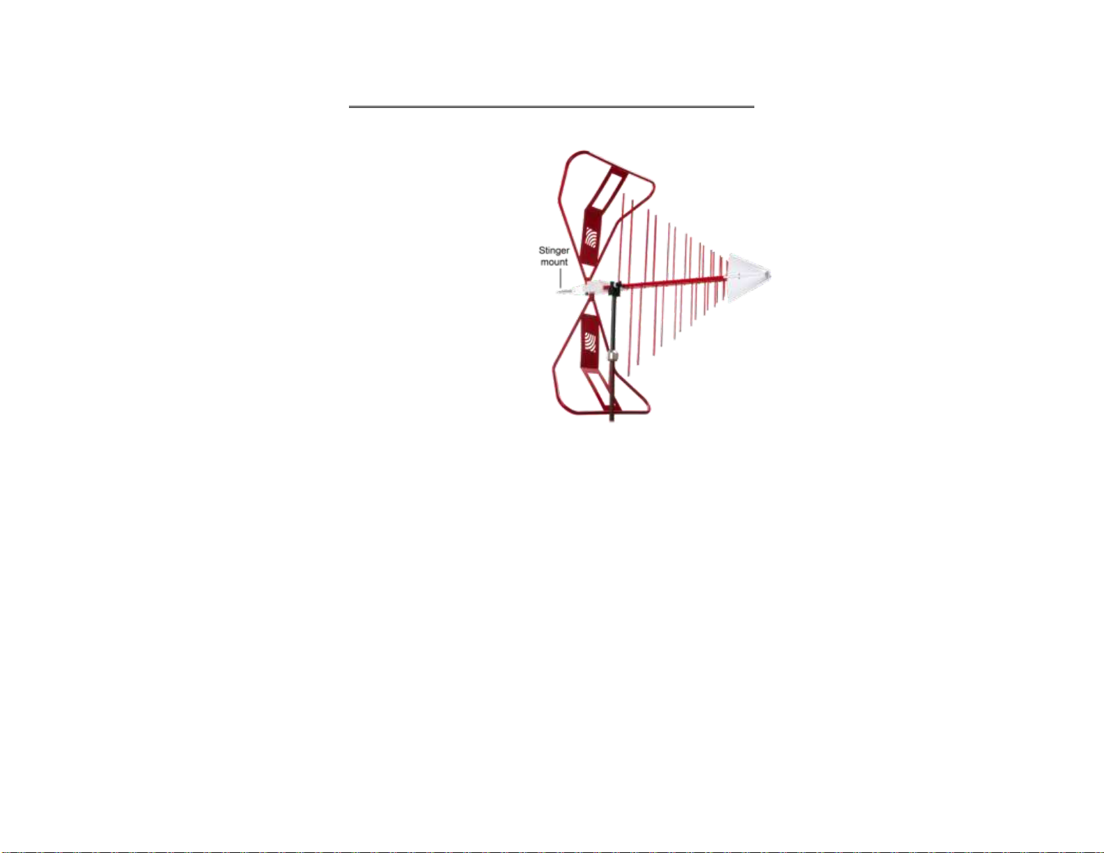
Model 3142E shown in vertical polarization
Introduction | 7
Page 8
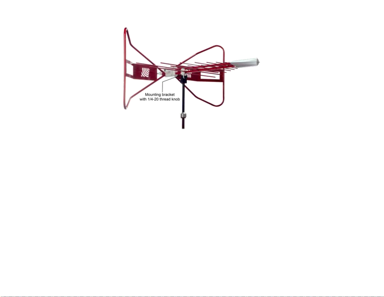
Model 3142E shown in horizontal polarization
The Model 3142E includes a stinger mount; it also includes a mounting bracket
and 1/4–20 thread knob to attach to an ETS-Lindgren tripod or tower adapter.
For the variety of mounting options available for the Model 3142E, see
Mounting Instructions on page 19.
8 | Introduction
Page 9
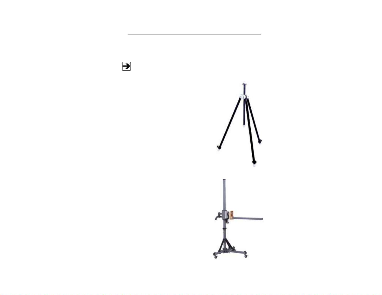
Tripod Options
For easy horizontal and vertical polarization, the ETS-Lindgren
Model 7-TR tripod is recommended.
4-TR Tripod—Constructed of linen phenolic
and delrin, designed with an adjustable center
post for precise height adjustments.
Maximum height is 2.0 m (80.0 in), and
minimum height is 94 cm (37.0 in). This tripod
can support up to an 11.8 kg (26.0 lb) load.
7-TR Tripod—Constructed of PVC and
fiberglass components, providing increased
stability for physically large antennas. The
unique design allows for quick assembly,
disassembly, and convenient storage. Allows
several different configurations, including
options for manual or pneumatic polarization.
Quick height adjustment and locking wheels
provide ease of use during testing. Maximum
height is 2.17 m (85.8 in), with a minimum
height of 0.8 m (31.8 in). This tripod can
support a 13.5 kg (30 lb) load.
ETS-Lindgren offers the following non-metallic, non-reflective tripods for use at
both indoor and outdoor EMC test sites.
Introduction | 9
Page 10

ETS-Lindgren Product Information Bulletin
See the ETS-Lindgren Product Information Bulletin included with your shipment
for the following:
Warranty information
Safety, regulatory, and other product marking information
Steps to receive your shipment
Steps to return a component for service
ETS-Lindgren calibration service
ETS-Lindgren contact information
10 | Introduction
Page 11
2.0 Maintenance
Before performing any maintenance,
follow the safety information in the
ETS-Lindgren Product Information
Bulletin included with your shipment.
Maintenance of the Model 3142E is
limited to external components such as
cables or connectors.
If you have any questions concerning
maintenance, contact ETS-Lindgren
Customer Service.
ETS-Lindgren may substitute a similar part or new part number with
the same functionality for another part/part number. Contact
ETS-Lindgren for questions about part numbers and ordering parts.
Part Description
Part Number
Polarizing Mounting Adapter
100989
Thread Insert
105861
For additional/optional mounting hardware, see Additional Mounting
Options on page 25.
WARRANTY
Annual Calibration
See the Product Information Bulletin included with your shipment for information
on ETS-Lindgren calibration services.
Replacement and Optional Parts
Following are the part numbers for ordering replacement or optional parts for the
Model 3142E.
Maintenance | 11
Page 12

Service Procedures
For the steps to return a system or system component to ETS-Lindgren for
service, see the Product Information Bulletin included with your shipment.
12 | Maintenance
Page 13
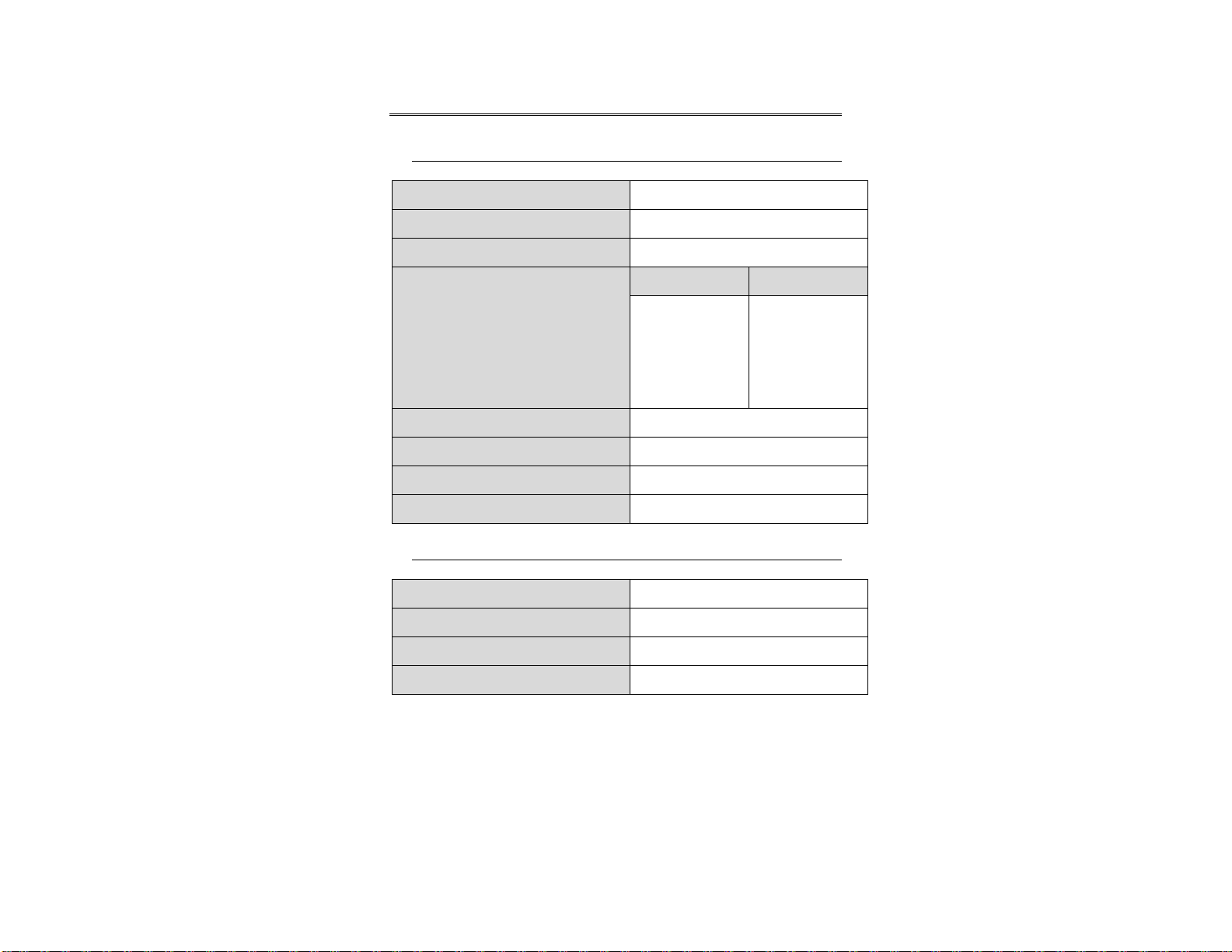
3.0 Specifications
Frequency Range:
26 MHz–6 GHz
Input Impedance (Nominal):
50 Ω
VSWR (Average):
2:1 above 50 MHz
Maximum Continuous Power
Continuous
Peak
30 MHz—60 MHz:
500 W
800 W
60 MHz—600 MHz:
1 kW
1.5 kW
600 MHz—1 GHz:
500 W
800 W
1 GHz—6 GHz:
200 W
300 W
Peak Power:
1.3 kW
Pattern Type:
Directional
Polarization:
Linear
Connector:
Type N female
Height (Overall):
76.2 cm (30 in)
Length:
139.16 cm (54.79 in)
Width:
133.75 cm (52.66 in)
Weight:
5.7 kg (12.5 lb)
Electrical Specifications
Physical Specifications
Specifications | 13
Page 14

This page intentionally left blank.
14 | Specifications
Page 15

4.0 Assembly Instructions
Before connecting any components, follow the
safety information in the ETS-Lindgren
Product Information Bulletin included with your
shipment.
The Model 3142E BiConiLog™ Antenna is comprised of the following parts:
Antenna
Bowtie elements (2)
10–32 thumbscrew knobs to attach bowtie elements (2)
Mounting bracket and mounting knob
Assembly Instructions | 15
Page 16

Attach Bowtie Elements
Photos of bowtie elements used in this section may differ from the
bowtie elements for your Model 3142E; the assembly procedure is the
same for both.
The Model 3142E ships with the bowtie elements detached. To attach the bowtie
elements:
16 | Assembly Instructions
Page 17

1. For stability, mount the Model 3142E onto a tripod or tower. See
Do not cross thread this connection or
permanent damage to the bowtie element could
occur.
Mounting Instructions on page 19 for the steps to mount the antenna.
2. Slide the narrow end of one of the bowtie elements into the
receptacle hole on the antenna balun, and then align the bowtie with
the receptacle on the balun.
3. Insert one of the 10–32 thumbscrew knobs into the opposite side of the
balun from where you inserted the bowtie. Slowly tighten the knob,
taking care not to cross thread the connection.
4. Repeat steps 2 and 3 for the second bowtie element.
Assembly Instructions | 17
Page 18

This page intentionally left blank.
18 | Assembly Instructions
Page 19

5.0 Mounting Instructions
Before connecting any components, follow the
safety information in the ETS-Lindgren
Product Information Bulletin included with your
shipment.
The Model 3142E antenna is a precision
measurement device. Handle with care.
Photos of bowtie elements used in this section may differ from the
bowtie elements for your Model 3142E; the mounting procedure is the
same for both.
Contact with any metal or non-metallic structure can capacitively load the
antenna, which may cause unrepeatable results. Therefore, make sure that no
part of the dipole elements or bowties is in contact with the tripod or tower,
particularly in vertically-polarized tests. Where possible, run the feed cable
straight one meter or more back from the Model 3142E BiConiLog™ Antenna
before dropping vertically.
Mounting Instructions | 19
Page 20

Using Included Mounting Adapters
100989 Polarizing Mounting
Adapter with 7/8–14 thread
receptacle
If you need to convert the polarizing
adapter to a 1/4–20 receptacle,
insert the 1/4–20 thread insert into
the polarizing adapter
105861 1/4–20 Thread Insert
In addition to the attached mounting bracket and mounting knobs, the
Model 3142E ships with these mounting adapters:
20 | Mounting Instructions
Page 21

To attach the included adapters to the Model 3142E:
Model 3142E
mounted onto 4-TR
using included
100989 Polarizing
Mounting Adapter
and 105861
1/4–20 Thread
Insert
Do not cross thread or permanent damage to the adapter and
thread insert could occur.
1. If required, insert the 1/4–20 thread insert into the mounting adapter.
2. Remove the mounting knob from the mounting bracket on the antenna.
3. Slide the mounting bracket onto the mounting adapter with the adapter
placed between the shoulders of the mounting bracket.
4. Thread the mounting knob through the mounting bracket, then through
the mounting adapter, and finally through the hex nut.
5. Tighten the mounting knob to secure the antenna.
6. Attach the mounting adapter and antenna to tripod or tower, as
required.
Mounting Instructions | 21
Page 22

Using the Stinger to Mount to a Model 2175 MiniMast
Do not use the stinger to mount the Model 3142E onto a 4-TR tripod.
Before you begin:
Install the center rotate boom (part# 108197) for rear-mount
stinger-type antennas.
Attach the included mounting adapter to the Model 3142E as
instructed in Using Included Mounting Adapters on page 20.
You will need one of the optional mounting knobs described in
7-TR and Mast Mounting Options on page 26. To order
optional mounting hardware, contact the ETS-Lindgren Sales
Department
1. Thread the antenna
feed or receiving
cable through the
center of the boom
so that the antenna
connector emerges
a few inches out of
the clamp end of
the boom.
The stinger mount provides on-axis rotation during 90° horizontal or vertical
polarization. The stinger enables you to mount the antenna directly to an
ETS-Lindgren 7-TR Tripod or mast.
22 | Mounting Instructions
Page 23

2. Attach the cable to
the Type N
connector at the
end of the stinger.
3. Slide the cable and
stinger into the
clamp on the boom,
carefully guiding
the cable out the
other end.
4. When you reach
the back of the
balun box, align it
with the boom
receptacle, and
then slide the
smaller portion of
the balun box into
the boom. This will
prevent rotation of
the antenna unless
the boom is being
polarized.
Mounting Instructions | 23
Page 24

5. Tighten the clamp
knobs on the boom
to secure the
antenna into place.
24 | Mounting Instructions
Page 25

Additional Mounting Options
4-TR MOUNTING OPTIONS
Following are additional options for mounting the Model 3142E onto an
ETS-Lindgren 4-TR tripod. Contact the ETS-Lindgren Sales Department for
information on ordering optional mounting hardware.
Mounting Instructions | 25
Page 26

7-TR AND MAST MOUNTING OPTIONS
However, following are
additional options for
mounting the
Model 3142E onto an
ETS-Lindgren 7-TR
Tripod Positioner.
Contact the
ETS-Lindgren Sales
Department for
information on ordering
optional mounting
hardware.
Non-stinger method to mount Model 3142E to 7-TR
The stinger on the Model 3142E enables you to mount to antenna directly to an
ETS-Lindgren 7-TR Tripod Positioner.
26 | Mounting Instructions
Page 27

Mast refers to 2070 Series, 2075, and 2175 Antenna Towers.
7-TR refers to 109042, 108983, and 108197 booms:
109042 boom—Straight boom; for general antenna mounting on a
7-TR
108983 boom—Offset boom; for general antenna mounting on a
7-TR with pneumatic or manual polarization; can also be used to
mount stinger-type antennas
108197 boom—Center rotate boom; for stinger-type antennas
only
Mounting Instructions | 27
Page 28

2X2 BOOM MOUNTING OPTIONS
2x2 boom refers to a typical 2-inch by 2-inch boom.
Following are additional options for mounting the Model 3142E onto a 2x2 boom.
Contact the ETS-Lindgren Sales Department for information on ordering optional
mounting hardware.
28 | Mounting Instructions
Page 29

6.0 Typical Data
Typical Antenna Factor and Gain
Distance for the ANSI 3-meter and 10-meter calibrations is measured from the
antenna midpoint, and for SAE 1-meter calibrations the distance is measured
from the antenna tip. Midpoint is defined as half the distance between the small
elements and the bowties, which is about 45 cm from the small end tip.
Typical Data | 29
Page 30

Typical VSWR
30 | Typical Data
Page 31

Typical Half Power Beamwidth
Typical Data | 31
Page 32

Typical Radiation Patterns
30 MHZ—50 MHZ
32 | Typical Data
Page 33

70 MHZ—90 MHZ
Typical Data | 33
Page 34

100 MHZ—200 MHZ
34 | Typical Data
Page 35

300 MHZ—400 MHZ
Typical Data | 35
Page 36

500 MHZ—600 MHZ
36 | Typical Data
Page 37

700 MHZ—800 MHZ
Typical Data | 37
Page 38

900 MHZ—1000 MHZ
38 | Typical Data
Page 39

2000 MHZ—3000 MHZ
Typical Data | 39
Page 40

4000 MHZ—5000 MHZ
40 | Typical Data
Page 41

6000 MHZ
Typical Data | 41
Page 42

This page intentionally left blank.
42 | Typical Data
Page 43

See the Product Information Bulletin included with your shipment for
the complete ETS-Lindgren warranty for your Model 3142E
BiConiLog™ Antenna.
Product Warranted
Duration of Warranty Period
Model 3142E BiConiLog Antenna
2 Years
Appendix A: Warranty
DURATION OF WARRANTIES FOR MODEL 3142E
All product warranties, except the warranty of title, and all remedies for warranty
failures are limited to two years.
Warranty | 43
 Loading...