

Page 1
Archived 09/23/10
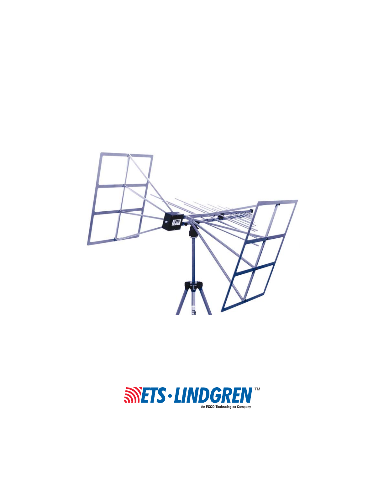
Model 3142B
BiConiLog
MANUAL
™
Antenna
© EMC TEST SYSTEMS, L.P. – MARCH 2002 REV C – PN 399229
Page 2

Introduction MODEL 3142B BICONILOG™ ANTENNA
Archived 09/23/10
EMC Test Systems, L.P. reserves the right to make changes to any product described herein in order to
improve function, design or for any other reason. Nothing contained herein shall constitute EMC Test
Systems, L.P. assuming any liability whatsoever arising out of the application or use of any product or
circuit described herein. EMC Test Systems, L.P. does not convey any license under its patent rights or the
rights of others.
© Copyright 2002 by EMC Test Systems, L.P. All Rights Reserved.
No part of this document may be copied by any means
without written permission from EMC Test Systems, L.P.
E-MAIL & INTERNET
Support@ets-lindgren.com
http://www.ets-lindgren.com
USA
1301 Arrow Point Dr., Cedar Park, TX 78613
P.O. Box 80589, Austin, TX 78708-0589
Tel 512.531.6400 Fax 512.531.6500
FINLAND
Euroshield OY
Mekannikontie 1
27510, Eura, Finland
Tel 358.2.838.3300
Fax 358.2.865.1233
SINGAPORE
Lindgren RF Enclosures Asia-Pacific
87 Beach Road
#06-02 Chye Sing Building
Singapore 189695
Tel 65.536.7078 Fax 65.536.7093
© EMC TEST SYSTEMS, L.P. – MARCH 2002
REV C – PN 399229
Page 3

MODEL 3142B BICONILOG™ ANTENNA Introduction
Archived 09/23/10
Table of Contents
INTRODUCTION ........................................................................................................................................ 1
ASSEMBLY & MOUNTING INSTRUCTIONS ....................................................................................... 4
APPLICATION WITHOUT THE OPTIONAL END PLATES .............................................................. 7
APPLICATION WITH THE OPTIONAL T BOW-TIE END PLATES ............................................... 9
TYPICAL DATA WITHOUT THE END PLATES ................................................................................ 10
TYPICAL DATA WITH THE END PLATES ........................................................................................ 13
SPECIFICATIONS .................................................................................................................................... 16
MAINTENANCE ....................................................................................................................................... 17
WARRANTY STATEMENT .................................................................................................................... 18
© EMC TEST SYSTEMS, L.P. – MARCH 2002
REV C – PN 399229
Page 4

Introduction MODEL 3142B BICONILOG™ ANTENNA
Archived 09/23/10
© EMC TEST SYSTEMS, L.P. – MARCH 2002
REV C – PN 399229
Page 5

MODEL 3142B BICONILOG™ ANTENNA Introduction
Archived 09/23/10
INTRODUCTION
The ETS-Lindgren EMCO brand Model 3142B
BiConiLog™ Antenna is designed as a dual-purpose
antenna that can be used for both emissions and immunity
applications. The Model 3142B is a hybrid linearly
polarized EMC antenna consisting of a log–periodic dipole
array (LPDA) and a single bow-tie antenna. Although bow-
ties have been used for all elements on log-periodic
antennas in the past, in EMC applications the advantage
gained is an extension of the useful low frequency range of
the typical LPDA’s from 100 down to 30 MHz. At 30
MHz, an efficient single dipole type antenna must be 5
meters long, whereas suitable performance is obtained here
with a 1.7 meter long bow-tie.
A simple wire outline bow-tie antenna is narrowband
compared to a sheet bow-tie or biconical, thus struts are
added to the Model 3142B bow-ties to better simulate the
broadband sheet bow-tie. The standard “self-balun” feed of
the log-periodic also provides a matched, balanced feed to
the bow-tie elements. Below 150 MHz, bow-tie radiation
dominates with a dipole-like pattern, while above 150 MHz
the radiation in the plane of the elements is directional.
To prevent cable pickup below 100 MHz, the Model 3142B
contains a “balun” which acts as a common-mode choke to
© EMC TEST SYSTEMS, L.P. – MARCH 2002 1
REV C – PN 399229
keep unbalanced current off the coaxial feed cable outer
shield. Even though the Model 3142B is highly balanced,
in vertically polarized measurements cable position can
effect results so it is recommended that the cable be
Page 6

Introduction MODEL 3142B BICONILOG™ ANTENNA
Archived 09/23/10
suspended horizontally back from the antenna at least 1
meter before any vertical drop.
The antenna has a mounting bracket and 1/4X20 UNC
knob for attaching to an ETS-Lindgren tripod or tower
adapter. Individual antenna factors and gain calibration data
is included with each antenna.
The Model 3142B optional end plates (Part Number
106572) are available to improve gain for immunity testing.
This option consists of two end plates that are easily
attached and detached by hand using captive screw knobs.
When the end plates are attached it creates a T shaped bow-
tie element.
For any dipole–type antenna to transmit or receive energy
most efficiently, its length must be nearly a half
wavelength, which is about 4.6 meters long at 30 MHz, and
2.8 meters long at 50 MHz. Unfortunately, this is too
unwieldy for many anechoic chambers and test sites. The
optional end plates of the Model 3142B make it look like
an antenna twice as long as its 1.4 meter length. The result
is about a 10 dB improvement in low-frequency transmit
gain and receive antenna factor compared to a same-length
regular bow-tie.
With the end plates attached to the Model 3142B bow-tie
elements the equivalent dipole electrical length is
2 © EMC TEST SYSTEMS, L.P. – MARCH 2002
REV C – PN 399229
increased, thereby decreasing resonant frequency and
increasing efficiency in the 20-60 MHz range. Similarly,
the regular bow-tie has a lower resonant frequency than an
Page 7

MODEL 3142B BICONILOG™ ANTENNA Introduction
Archived 09/23/10
equal length single-wire dipole. The T end plate option has
its first resonance at a frequency where its length is about
0.22 λ, a regular bow-tie at a length of 0.3 λ, and a tuned
dipole at about a length of 0.48 λ. Thus at 50 MHz the 1.4m
long end plate option of the Model 3142B behaves like at
2.8 m tuned dipole. Cross-polar radiation is minimized
because current flow on one of the T end frames is almost
exactly cancelled by the oppositely-phased current on the
other T end.
© EMC TEST SYSTEMS, L.P. – MARCH 2002 3
REV C – PN 399229
Page 8

Assembly & Mounting Instructions MODEL 3142B BICONILOG™ ANTENNA
Archived 09/23/10
ASSEMBLY & MOUNTING INSTRUCTIONS
The Model 3142B consists of the following:
1 ea. Antenna
2 ea. Bow-Tie Elements
2 ea. 1/4x20 Knobs for attaching Bow-Tie elements.
2 ea. Protective End Caps on the Bow-Tie elements.
8 ea. Screws to attach the Protective End Caps to
the Bow-Tie elements.
The Optional End Plate package consists of:
2 ea. T Bow-Tie Endplates
8 ea. Thumbscrew Knobs for attaching the
endplates to the bow-tie elements.
Step 1. Mount the Model 3142B on a tripod or tower
adapter, without the bow-tie elements attached.
Step 2. Slide the narrow end of one of the bow-tie elements
into the receptacle hole on the boom and align the
bow-tie with the receptacle on the boom as shown
in the picture. Insert one of the 1/4x20 knobs into
the opposite side of the boom where the bow-tie
was just inserted.
Slowly tighten the knob taking care not to cross
thread the connection. Cross threading this
connection could cause permanent damage to
the bow-tie element. Repeat Step 2 for the other
bow-tie element.
Bow-tie element connection to antenna
4 © EMC TEST SYSTEMS, L.P. – MARCH 2002
REV C – PN 399229
boom.
Page 9

MODEL 3142B BICONILOG™ ANTENNA Assembly & Mounting Instructions
Archived 09/23/10
Step 3. Connecting the optional end plates to
create the T bow-ties. The Model 3142B
has a black end cap on each of the bow-
tie elements to protect them. In order to
utilize the optional end plates that create
the T bow-ties, the black end caps must
first be removed. Using a Phillips head
screwdriver carefully remove the four
Bow-tie element receptacle hole
and optional end plate with
screw knob.
screws in each of the bow-tie end caps.
Store the end caps and the screws in a
safe place, as they should be reinstalled
when you are done using the optional end
plates.
Align the four holes on the wide end of the bow-tie element
with the four holes on the end plate. Insert and slowly
tighten each of the 4 small knobs in the receptacle holes. Be
careful not to cross-thread this connection or permanent
damage to bow-tie could occur. Repeat Step 3 for the other
optional end plate.
Contact with any metal or non-metallic structure can
capacitively load the antenna, which may cause
unrepeatable results. Therefore, care must be taken to
ensure that no part of the dipole elements or bow-ties are in
contact with the tripod or tower, particularly in vertically-
polarized tests. Where possible, run the feed cable straight
at least 1 meter or more back from the Model 3142B before
dropping vertically.
© EMC TEST SYSTEMS, L.P. – MARCH 2002 5
REV C – PN 399229
Both horizontal and vertical polarization is easily
accomplished when the Model 3142B with the optional end
Page 10

Assembly & Mounting Instructions MODEL 3142B BICONILOG™ ANTENNA
Archived 09/23/10
plates is mounted on a tower. Vertical polarization on a
tripod requires special consideration. Since immunity
power requirements are many dB lower for vertical
polarization, the T end frames can be removed when
mounting vertically on a standard tripod. A special tripod is
available from ETS-Lindgren for vertical polarization with
T bow-ties intact. Please contact ETS-Lindgren for the
recommended mounting scheme.
6 © EMC TEST SYSTEMS, L.P. – MARCH 2002
REV C – PN 399229
Page 11

MODEL 3142B BICONILOG™ ANTENNA Application Without the Optional End Plates
Archived 09/23/10
APPLICATION WITHOUT THE OPTIONAL END PLATES
For emissions measurements, electric fields strength in
dB[V/m] is obtained from
E(dB[V/m]) = V(dB[V]+AF(dB[1/m])+α(dB)
where V is the receiver or spectrum analyzer voltage
reading, AF is antenna factor (see attached calibration
data), and α is cable loss, if cable losses are non-negligible.
For immunity testing, the electrical field strength generated
at a distance d can be approximated by
E(V/m) = √(30 P g) / d
where d is in meters, g is the numeric gain (10
attached calibration data), and P is antenna net input power
in watts. An estimate of the power required for any field
strength E can be obtained from Figure 4 in the Typical
Data section below, which shows power required in watts
to generate 1 V/m. Power shown is calculated from the
measured gain and corrected for VSWR. For any other field
strength, multiply the power in watts by desired E-field
squared, or
P(E V/m) = E2 P(1 V/m)
Actual transmitted field strength should be verified using
an ETS-Lindgren electric field probe or equivalent. An
estimate of the power required taking VSWR into account
G[dB]/10
, see
© EMC TEST SYSTEMS, L.P. – MARCH 2002 7
REV C – PN 399229
is obtained from
= Pn / {1-[(VSWR-1)/(VSWR+1)]2}
P
f
where Pf is the forward (amplifier output) power and Pn is
the new power as discussed above.
Page 12

Application Without the Optional End Plates MODEL 3142B BICONILOG™ ANTENNA
Archived 09/23/10
For IEC 1000-4-3 type testing, the antenna tip can be
placed at any distance between 1 and 3 m from the EUT as
long as the front face plane is illuminated according to the
–0,+6 dB specification.
8 © EMC TEST SYSTEMS, L.P. – MARCH 2002
REV C – PN 399229
Page 13

MODEL 3142B BICONILOG™ ANTENNA Application With The Optional T Bow-Tie End Plates
()(
Archived 09/23/10
APPLICATION WITH THE OPTIONAL
T BOW-TIE END PLATES
For emissions testing it is recommended that the Model
3142B be used without the optional end plates. The
coupling of the endplates to ground will create higher
uncertainty values, particularly in the vertical polarization.
For more information about this issue see the article “Understanding
the measurement uncertainties of the bicon/log hybrid antenna” by
Zhong Chen in the 1999 issue of Item The International Journal of
EMC.
For immunity testing, the electric field strength generated
at a distance d can be approximated by the formula
30
V/m =
E
()
where d is in meters, g is the numeric gain (10
attached calibration data) and P is antenna net input in
watts. An estimate of the power required for any field
strength E can be obtained from Figure 3 or 4 in the
Typical Data section below, which shows power required
in watts to generate 1 V/m. For any other field strength not
show, multiply the power in watts by the desired E-field
squared, or
PE E PV/m V/m=
Actual transmitted field strength should be verified using
Pg
d
G[dB]/10
2
1
)
, see
© EMC TEST SYSTEMS, L.P. – MARCH 2002 9
REV C – PN 399229
an ETS-Lindgren electric field probe or equivalent. For
IEC 1000-4-3 type testing, the antenna tip cam be placed at
any distance between 1 and 3 m from the EUT as long as
the front face plane is illuminated according to the –0,+6
Page 14

Typical Data without the End Plates MODEL 3142B BICONILOG™ ANTENNA
Archived 09/23/10
dB uniform field specification. In general, closer distances
require less power to create a given field strength.
TYPICAL DATA WITHOUT THE END PLATES
Figure 1 shows typical 26-200 MHz VWSR for the Model
3142B.
Figure 2 shows typical Model 3142B 26-2000 MHz
antenna factors. Distance for the ANSI 3 and 10 meter
calibrations is measured from the antenna midpoint, while
for SAE 1 meter calibrations the distance is measured from
the antenna tip. Midpoint is defined as half the distance
between the small elements and the bow-ties, which is
about 45 cm from the small end tip.
Figure 3 shows typical Model 3142B 26-2000 MHz gain,
derived from the 3 antenna method antenna factors.
Figure 4 gives approximate input power required to
generate 1 V/m at 1 and 3 meters. For any other field
strength E, multiply power in watts by E2.
10 © EMC TEST SYSTEMS, L.P. – MARCH 2002
REV C – PN 399229
Page 15

MODEL 3142B BICONILOG™ ANTENNA Typical Data without the End Plates
Archived 09/23/10
100
10
VSWR
1
10 100 1,000
35
30
25
20
dB[1/m]
15
10
MHz
Figure 1. Model 3142B Typical VSWR
1 m
3 m
10 m
© EMC TEST SYSTEMS, L.P. – MARCH 2002 11
REV C – PN 399229
5
0 200 400 600 800 1,000 1,200 1,400 1,600 1,800 2,000
MHz
Figure 2. Model 3142B Typical Antenna Factor
Page 16

Typical Data without the End Plates MODEL 3142B BICONILOG™ ANTENNA
Archived 09/23/10
10
5
0
-5
-10
dBi
-15
1 m
-20
-25
-30
10 100 1,000
3 m
10 m
W
MHz
Figure 3. Model 3142B Typical Gain
1,000
100
10
1
0.1
0.01
0.001
10 100 1,000
1 m
3 m
12 © EMC TEST SYSTEMS, L.P. – MARCH 2002
REV C – PN 399229
MHz
Figure 4. Model 3142B Typical 1 V/m Power Required
Page 17

MODEL 3142B BICONILOG™ ANTENNA Typical Data with the End Plates
Archived 09/23/10
TYPICAL DATA WITH THE END PLATES
Figure 1 shows typical 26-2000 MHz VSWR for the Model
3142B with optional end plates.
Figure 2 shows typical Model 3142B with optional end
plates antenna factors from 26-2000 MHz. Distance for the
ANSI 3 and 10 meter calibrations is measured from the
antenna midpoint, while for SAE 1 meter calibrations the
distance is measured from the antenna tip. Midpoint is
defined as half the distance between the small elements and
the bow-ties, which is about 45 cm from the small end tip.
Figure 3 shows typical Model 3142B 26-2000 MHz
forward power with optional end plates required for 1, 3,
and 10 V/m at 1 m from the tip of the antenna, while Figure
4 is for 3 m from the antenna tip.
The power shown was measured over a ground plane with
1.5m transmit antenna and probe height, horizontal
polarization. Horizontal polarization is the worst-case
power required; typically less power is required for vertical
polarization. In practice, many users place ferrite tiles on
the ground between the antenna and probe to reduce
reflected-ray interference. For any other field strength E,
2
multiply the power in watts for 1 V/m by E
.
© EMC TEST SYSTEMS, L.P. – MARCH 2002 13
REV C – PN 399229
Page 18

Typical Data with the End Plates MODEL 3142B BICONILOG™ ANTENNA
Archived 09/23/10
100
R
10
SW
1
10 100 1000
MHz
Figure 1. Model 3142B typical VSWR.
35
]
m
/
1
[
dB
F
30
25
20
1 m
3 m
10 m
A
15
10
5
10 100 1000
14 © EMC TEST SYSTEMS, L.P. – MARCH 2002
REV C – PN 399229
MHz
Figure 2. Model 3142B typical antenna factor.
Page 19

MODEL 3142B BICONILOG™ ANTENNA Typical Data with the End Plates
Archived 09/23/10
1000
1 V/m
3 V/m
100
10 V/m
3 V/m 80% AM
10
W
1
0.1
20 30 40 50 60 70 80
MHz
Figure 3. Model 3142B typical 1 m forward power.
1000
1 V/m
3 V/m
10 V/m
100
10
W
1
0.1
20 30 40 50 60 70 80
MHz
Figure 4. Model 3142B typical 3 m forward power.
© EMC TEST SYSTEMS, L.P. – MARCH 2002 15
REV C – PN 399229
Page 20

Specifications MODEL 3142B BICONILOG™ ANTENNA
ς
ς
Archived 09/23/10
SPECIFICATIONS
ELECTRICAL
3142B
Frequency
Range
Input
Impedance
VSWR
CW power
Symmetry
Connector N female N female
With Standard Bow-tie
Elements
26-2000 MHz
50
50
2:1 average 2:1 average
1 kW, above 100 MHz
300 W, below 100 MHz
+/- 0.5 dB +/- 0.5 dB
With Optional End Plates
26-2000 MHz
1 kW, above 60 MHz
500 W, below 60 MHz
PHYSICAL
3142B
Height (bow-tie)
Width (bow-tie)
Depth (boom length) 90 cm
Weight 4 kg
With Standard
Bow-tie Elements
75 cm
29.5 in
135 cm
53.1 in
35.4 in
8.8 lb
With Optional
End Plates
75 cm
29.5 in
136 cm
53.5 in
132 cm
51.9 in
6.8 kg
14.9 lb
16 © EMC TEST SYSTEMS, L.P. – MARCH 2002
REV C – PN 399229
Page 21

MODEL 3142B BICONILOG™ ANTENNA Maintenance
Archived 09/23/10
MAINTENANCE
To ensure reliable and repeatable long-term performance,
annual recalibration of your antenna by ETS-Lindgren’s
experienced technicians is recommended. Our staff can
recalibrate almost any type or brand of antenna. Please call
to receive a Service Order Number prior to sending an
antenna to us for calibration.
For more information about our calibration services or to
place an order for antenna calibration visit our calibration
website at http://www.antennacalibration.com/.
© EMC TEST SYSTEMS, L.P. – MARCH 2002 17
REV C – PN 399229
Page 22

Warranty Statement MODEL 3142B BICONILOG™ ANTENNA
Archived 09/23/10
WARRANTY STATEMENT
EMC Test Systems, L.P., hereinafter referred to as the Seller, warrants that standard EMCO
products are free from defect in materials and workmanship for a period of two (2) years from
date of shipment. Standard EMCO Products include the following:
Antennas, Loops, Horns
GTEM cells, TEM cells, Helmholtz Coils
LISNs, PLISNs, Rejection cavities & Networks
Towers, Turntables, Tripods, & Controllers
Field Probes, Current Probes, Injection Probes
If the Buyer notifies the Seller of a defect within the warranty period, the Seller will, at the Seller’s
option, either repair and/or replace those products that prove to be defective.
There will be no charge for warranty services performed at the location the Seller designates.
The Buyer must, however, prepay inbound shipping costs and any duties or taxes. The Seller will
pay outbound shipping cost for a carrier of the Seller’s choice, exclusive of any duties or taxes. If
the Seller determines that warranty service can only be performed at the Buyer’s location, the
Buyer will not be charged for the Seller’s travel related costs.
This warranty does not apply to:
Normal wear and tear of materials
Consumable items such as fuses, batteries, etc.
Products that have been improperly installed, maintained or used
Products which have been operated outside the specifications
Products which have been modified without authorization
Calibration of products, unless necessitated by defects
THIS WARRANTY IS EXCLUSIVE. NO OTHER WARRANTY, WRITTEN OR ORAL, IS
EXPRESSED OR IMPLIED, INCLUDING BUT NOT LMITED TO, THE IMPLIED WARRANTIES
OF MERCHANTABILITY AND FITNESS FOR A PARTICULAR PURPOSE. THE REMEDIES
PROVIDED BY THIS WARRANTY ARE THE BUYER’S SOLE AND EXCLUSIVE REMEDIES.
IN NO EVENT IS THE SELLER LIABLE FOR ANY DAMAGES WHATSOEVER, INCLUDING
BUT NOT LIMITED TO, DIRECT, INDIRECT, SPECIAL, INCIDENTAL, OR CONSEQUENTIAL
DAMAGES, WHETHER BASED ON CONTRACT, TORT, OR ANY OTHER LEGAL THEORY.
Note: Please contact the Seller’s sales department for a Return Materials Authorization (RMA)
number before shipping equipment to us.
18 © EMC TEST SYSTEMS, L.P. – MARCH 2002
REV C – PN 399229
 Loading...