

Page 1
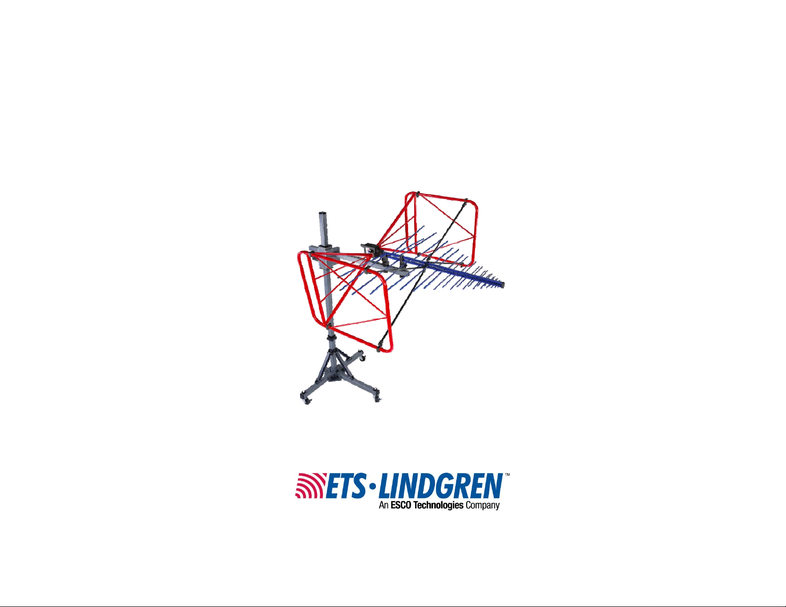
Model 3140B
BiConiLog™ Antenna
User Manual
Model 3140B mounted onto a 7-TR tripod (not included)
Page 2

ETS-Lindgren L.P. reserves the right to make changes to any product described
herein in order to improve function, design, or for any other reason. Nothing
contained herein shall constitute ETS-Lindgren L.P. assuming any liability
whatsoever arising out of the application or use of any product or circuit
described herein. ETS-Lindgren L.P. does not convey any license under its
patent rights or the rights of others.
© Copyright 2000–2010 by ETS-Lindgren L.P. All Rights Reserved. No part
of this document may be copied by any means without written permission
from ETS-Lindgren L.P.
Trademarks used in this document: The ETS-Lindgren logo, MiniMast, and
BiConiLog are trademarks of ETS-Lindgren L.P.
Revision Record | MANUAL,MODEL 3140 | Part #399258, Rev. E
Revision Description Date
A Initial Release November, 2000
B Edits/updates January, 2002
C Edits/updates January, 2003
D Edits/updates May, 2003
E Rebrand May, 2010
ii |
Page 3

Table of Contents
Notes, Cautions, and Warnings ................................................ v
1.0 Introduction .......................................................................... 7
About Mounting the Model 3140B ................................................................. 9
7-TR Tripod Positioner........................................................................... 9
ETS-Lindgren Product Information Bulletin ................................................. 10
2.0 Maintenance ....................................................................... 11
About Calibration ......................................................................................... 11
Service Procedures ..................................................................................... 11
3.0 Specifications ..................................................................... 13
Electrical Specifications ............................................................................... 13
Physical Specifications ................................................................................ 13
4.0 Assembly Instructions ...................................................... 15
Model 3140B Components .......................................................................... 15
Model 3140B Assembled ............................................................................. 16
Steps to Assemble the Model 3140B ........................................................... 17
Attach Bow Tie Elements..................................................................... 17
Attach T Leg Elements ........................................................................ 19
Attach Diagonal Struts ......................................................................... 21
Attach V Elements ............................................................................... 22
5.0 Mounting Instructions ....................................................... 23
Included Mounting Adapters ........................................................................ 23
Using Included Adapters to Mount to an Offset Boom ................................. 24
Attach Included Mounting Adapters to Model 3140B .......................... 24
Attach Model 3140B to an ETS-Lindgren Offset Boom ....................... 25
Mounting Illustrations ................................................................................... 26
Model 3140B on 7-TR Tripod Positioner ............................................. 26
Model 3140B on Model 2075 MiniMast ............................................... 27
Model 3140B on Model 2070/2071 Antenna Positioning Mast ............ 28
Additional Mounting Options ........................................................................ 29
7-TR and Mast Mounting Options ........................................................ 29
2x2 Boom Mounting Options ............................................................... 30
6.0 Application ......................................................................... 31
| iii
Page 4

7.0 Typical Data ........................................................................ 33
Model 3140B Typical VSWR ....................................................................... 33
Model 3140B Typical Antenna Factors ........................................................ 34
Model 3140B Gain ....................................................................................... 35
Model 3140B Typical Forward Power (FP) .................................................. 36
Typical 1 Meter FP Based on 1 Meter Antenna Factor ....................... 37
Typical 3 Meter FP Based on 3 Meter Antenna Factor ....................... 38
Typical 3 Meter FP Over Ferrite Tile.................................................... 39
Typical 3 Meter FP Measured Over Conducting Ground .................... 40
Appendix A: Warranty ............................................................. 41
iv |
Page 5
Notes, Cautions, and Warnings
Note: Denotes helpful information intended to
See the ETS-Lindgren Product Information Bulletin for safety,
regulatory, and other product marking information.
provide tips for better use of the product.
Caution: Denotes a hazard. Failure to follow
instructions could result in minor personal injury
and/or property damage. Included text gives proper
procedures.
Warning: Denotes a hazard. Failure to follow
instructions could result in SEVERE personal injury
and/or property damage. Included text gives proper
procedures.
| v
Page 6

This page intentionally left blank.
vi |
Page 7
1.0 Introduction
The ETS-Lindgren
Model 3140B BiConiLog
high-field antenna in the
bow tie/log periodic family,
providing the highest
field-to-power ratio at low
frequencies of any of the
BiConiLog antennas. The
Model 3140B is designed
specifically to generate the field
levels required for
immunity/susceptibility tests
required by standards such as
IEC/EN 61000-4-3 using the
lowest amount of input power
possible.
A BiConiLog antenna combines a broadband biconical-like bow tie antenna with
a standard log periodic dipole array (LPDA) to replace the traditional use of two
antennas in the 26 MHz to 3000 MHz electromagnetic compatibility (EMC) test
frequency range. Many EMC antennas are variations of a standard tuned dipole,
which must be nearly half a wavelength long to transmit or receive energy most
efficiently; at 26 MHz, a tuned dipole would have to be approximately 5.3 meters
long, 4.6 meters long at 30 MHz, and 2.8 meters long at 50 MHz. This is
unwieldy for many anechoic chambers and test sites. The end plates of the
Model 3140B T bow ties make the bow tie antenna segment look like an antenna
twice as long as the actual 1.6 meter length. The result is about a 10 dB
improvement in low frequency transmit gain compared to a regular bow tie of the
same length.
TM
is a
Although bow ties have been used for all of the elements on some log periodic
antenna designs in the past, in EMC applications the advantage gained is an
extension of the useful low frequency range of the typical LPDA from 100 MHz
down to 26 MHz. At 26 MHz, an efficient single dipole type antenna must be over
five meters long, whereas suitable performance is obtained here with a 1.6 meter
bow tie. A simple wire outline bow tie antenna is narrowband compared to a
sheet bow tie or biconical, so struts are added to the Model 3140B bow ties to
better simulate the broadband sheet bow tie.
Introduction | 7
Page 8

The unique feature of the Model 3140B is the T bow tie elements. A T bow tie
increases the equivalent dipole electrical length, thereby decreasing resonant
frequency and increasing efficiency in the 20 MHz to 60 MHz range. Similarly, a
regular bow tie has a lower resonant frequency than an equal length single-wire
dipole. The T bow tie has the first resonance at a frequency where the length is
about 0.22
0.48
like a 2.8 meter tuned dipole. Cross-polar radiation is minimized because current
flow on one of the T end frames is almost exactly cancelled by the
oppositely-phased current on the other T end.
The standard self-balun feed of the log periodic also provides a matched
balanced feed to the bow tie elements. To prevent cable pickup below 100 MHz
and to improve matching to the bow tie elements, the Model 3140B contains a
balun transformer which acts as a common-mode choke to keep unbalanced
current off the coaxial feed cable outer shield, as well as adding some additional
inductance to improve impedance matching to the bow ties. Even though the
Model 3140B is highly balanced (symmetry +/- 0.5 dB), in vertically polarized
measurements cable position can effect results, so it is recommended that the
cable be suspended horizontally back from the antenna at least one meter before
any vertical drop. Below 150 MHz bow tie radiation dominates with a dipole-like
pattern, while above 150 MHz the radiation in the plane of the elements is
directional.
λ, a regular bow tie at a length of 0.3λ, and a tuned dipole at about
λ. Thus at 50 MHz the 1.4 meter long T bow tie of the Model 3140B behaves
The Model 3140B is designed only for immunity testing. The large size
of the antenna makes it impractical for emissions testing where height
scanning is required, and the bow tie end plates increase the
measurement uncertainty when the antenna is polarized vertically. For
that reason, individual calibrations are not provided for the
Model 3140B.
8 | Introduction
Page 9
About Mounting the Model 3140B
The Model 3140B can be mounted on the 2-in square booms of these
ETS-Lindgren products:
• Model 7-TR Tripod Positioner
• Model 2075 MiniMast™
• Model 2070/2071 Antenna Positioning Mast
See Mounting Illustrations on page 26 for diagrams showing the
Model 3140B mounted to these ETS-Lindgren products.
For the variety of mounting options available for the Model 3140B, see
Mounting Instructions on page 23.
7-TR TRIPOD POSITIONER
ETS-Lindgren offers the non-metallic, non-reflective Model 7-TR for use at both
indoor and outdoor EMC test sites.
Constructed of PVC and fiberglass
components, providing increased stability
for physically large antennas. The unique
design allows for quick assembly,
disassembly, and convenient storage.
Allows several different configurations,
including options for manual or pneumatic
polarization. Quick height adjustment and
locking wheels provide ease of use during
testing. Maximum height is 2.17 m (85.8 in),
with a minimum height of 0.8 m (31.8 in).
This tripod can support a 13.5 kg (30 lb)
load.
Introduction | 9
Page 10

ETS-Lindgren Product Information Bulletin
See the ETS-Lindgren Product Information Bulletin included with your shipment
for the following:
• Warranty information
• Safety, regulatory, and other product marking information
• Steps to receive your shipment
• Steps to return a component for service
• ETS-Lindgren calibration service
• ETS-Lindgren contact information
10 | Introduction
Page 11
2.0 Maintenance
Before performing any maintenance,
follow the safety information in the
ETS-Lindgren Product Information
Bulletin included with your shipment.
WARRANTY
Maintenance of the Model 3140B is
limited to external components such as
cables or connectors.
If you have any questions concerning
maintenance, contact ETS-Lindgren
Customer Service.
About Calibration
The Model 3140B BiConiLog
testing, so the generated field is measured with a calibrated
field probe, not the Model 3140B. For that reason, it is not required
that the Model 3140B be recalibrated regularly. If you would like to
have your Model 3140B antenna verified or serviced please contact
ETS-Lindgren Calibration.
See the Product Information Bulletin included with your shipment for information
on ETS-Lindgren calibration services.
TM
Antenna was designed for immunity
Service Procedures
For the steps to return a system or system component to ETS-Lindgren for
service, see the Product Information Bulletin included with your shipment.
Maintenance | 11
Page 12

This page intentionally left blank.
12 | Maintenance
Page 13
3.0 Specifications
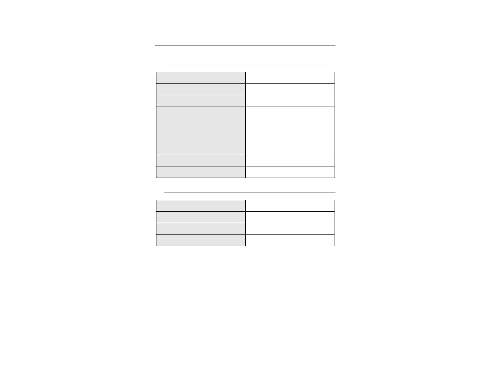
Electrical Specifications
Frequency Range: 26 MHz–3000 MHz
Input Impedance: 50 Ω
VSWR (Average): 2:1
CW Power (Average):
Symmetry: +/- 0.5 dB
Connector: Type N female
• 26 MHz to 150 MHz = 750 W
• 150 MHz to 600 MHz = 500 W
• 600 MHz to 1 GHz = 365 W
• 1 GHz to 3 GHz = 200 W
Physical Specifications
Height (T Bow Tie): 76.65 cm (30.18 in)
Width (T Bow Tie): 161.5 cm (63.60 in)
Depth (Length): 151.3 cm (59.6 in)
Weight: 10 kg (22 lb)
Specifications | 13
Page 14

This page intentionally left blank.
14 | Specifications
Page 15

4.0 Assembly Instructions
Before connecting any components, follow the
safety information in the ETS-Lindgren
Product Information Bulletin included with your
shipment.
Model 3140B Components
The Model 3140B BiConiLog™ Antenna consists of the following:
• Antenna
• Bow tie elements (2)
• Long T leg elements (2)
• Diagonal struts (4)
• V elements (2)
• Boom assembly
• Mount knobs (2): one 7/8-in (104169) and one 1/4-in (104136)
• Polarizing adapters (100989) for booms with 7/8-in mount holes (2)
• Thread inserts (105861B) 7/8 in-to-1/4 in (2)
Assembly Instructions | 15
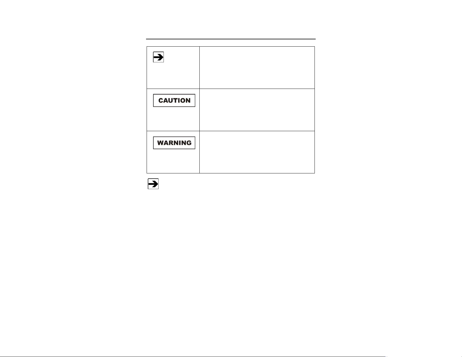
Page 16

Model 3140B Assembled
16 | Assembly Instructions
Page 17

Steps to Assemble the Model 3140B
A
TTACH BOW TIE ELEMENTS
To eliminate stress and prevent damage to the
balun box connection, you must support the
antenna while attaching the bow tie elements.
1. Place the bow tie vertically on the floor and hold the antenna
horizontally. See illustration on next page.
2. Fit the bow tie into one side of the balun.
3. Insert and tighten the knob.
4. Carefully place the antenna in a vertical position with the feet of the
balun box level and on a flat surface.
5. Repeat steps 2 and 3 to attach the second bow tie element to the
balun box.
Assembly Instructions | 17
Page 18

18 | Assembly Instructions
Page 19

ATTACH T LEG ELEMENTS
6. Insert one long T leg element into the clamp and tighten the clamp
screws. See illustration on next page.
7. Repeat for second T leg element.
Assembly Instructions | 19
Page 20

20 | Assembly Instructions
Page 21

ATTACH DIAGONAL STRUTS
8. Attach the four diagonal struts.
• Loosen the thumbscrew at each strut mount on the T leg element and
at the boom.
• Place the pocket of the straight end facing the raised face of each
mount.
• Tighten the thumbscrew.
Assembly Instructions | 21
Page 22

ATTACH V ELEMENTS
9. Attach the V elements and tighten the thumbscrews through the boom
The Model 3140B is now ready for mounting to a tripod or mast. See
Mounting Instructions on page 23.
22 | Assembly Instructions
Page 23

5.0 Mounting Instructions
Before connecting any components, follow the
safety information in the ETS-Lindgren
Product Information Bulletin included with your
shipment.
The Model 3140B is a precision measurement
device. Handle with care.
Do not mount the Model 3140B onto an ETS-Lindgren 4-TR Tripod.
Included Mounting Adapters
The Model 3140B BiConiLog™ ships with these mounting adapters:
• 100989 Polarizing Mounting
Adapter with 7/8–14 thread
receptacle (2)
If you need to convert the polarizing
adapter to a 1/4–20 receptacle,
insert the 1/4–20 thread insert into
the polarizing adapter
• 105861B 1/4–20 Thread Insert (2)
Mounting Instructions | 23
Page 24

Using Included Adapters to Mount to an Offset Boom
A
TTACH INCLUDED MOUNTING ADAPTERS TO MODEL
To allow manual polarization of the Model 3140B, install the 100989
polarizing adapters with the curve at the top of each adapter facing the
same direction. To prohibit manual polarization, install one adapter
with the curve facing the opposite direction from the other.
3140B
1. Place one 100989 polarizing adapter between the shoulders of one of
the mounting brackets on the antenna.
Do not cross thread or permanent damage to the adapter and
thread insert could occur.
2. Thread a bracket knob through the mounting bracket, then through the
polarizing adapter, and finally through the hex nut.
3. Tighten the mounting knob to secure the antenna.
4. Repeat steps 1, 2, and 3 for the remaining polarizing adapter and
mounting bracket.
24 | Mounting Instructions
Page 25

ATTACH MODEL 3140B TO AN ETS-LINDGREN OFFSET BOOM
1. Place the Model 3140B onto the offset boom with the attached
polarizing adapters flat against the top surface of the boom.
2. Holding the Model 3140B securely, insert one 105861B 1/4–20 thread
insert into the underside of the offset boom.
3. Attach the two mount knobs and tighten to secure the Model 3140B to
the offset boom.
Mounting Instructions | 25
Page 26

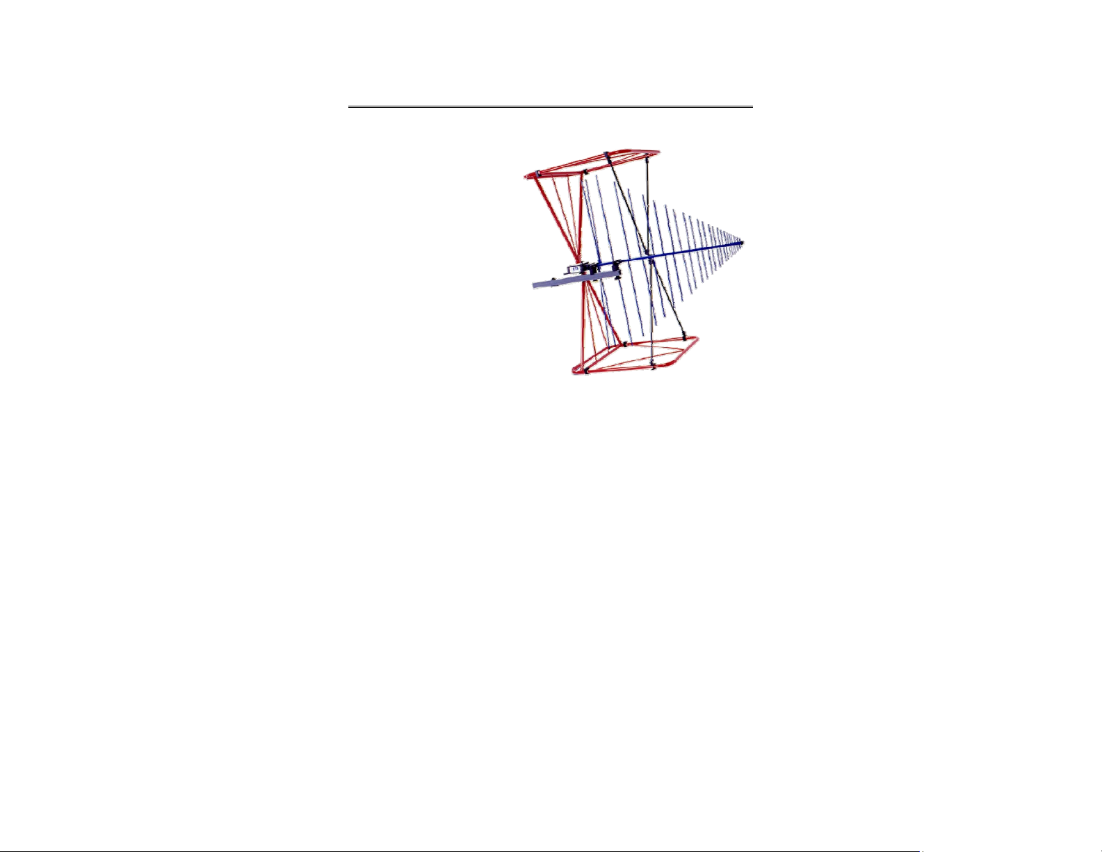
Mounting Illustrations
MODEL 3140B ON 7-TR TRIPOD POSITIONER
26 | Mounting Instructions
Page 27

M
ODEL
3140B
ON MODEL
2075 M
INIMAST
Mounting Instructions | 27
Page 28

M
ODEL
3140B
ON MODEL
2070/2071 A
NTENNA POSITIONING MAST
28 | Mounting Instructions
Page 29

Additional Mounting Options
7-TR AND MAST MOUNTING OPTIONS
Following are options for mounting the Model 3140B onto an ETS-Lindgren 7-TR
Tripod or mast. Contact the ETS-Lindgren Sales Department for information on
ordering optional mounting hardware.
Mast refers to 2070 Series, 2075, and 2175 Antenna Towers.
7-TR refers to 109042, 106328, and 108197 booms:
• 109042 boom—Straight boom; for general antenna mounting on a
7-TR
• 106328 boom—Offset boom; for general antenna mounting on a
7-TR with pneumatic or manual polarization
• 108197 boom—Center rotate boom; for rear-mount stinger-type
antennas only
Mounting Instructions | 29
Page 30

2X2 BOOM MOUNTING OPTIONS
Following are options for mounting the Model 3140B onto a 2x2 boom. Contact
the ETS-Lindgren Sales Department for information on ordering optional
mounting hardware.
2x2 boom refers to a
typical 2-inch by 2-inch
boom
30 | Mounting Instructions
Page 31

G[dB]/10
6.0 Application
After mounting the Model 3140B BiConiLogTM, connect an N-type coaxial cable
from the antenna connector to a signal generator or amplifier. Contact with any
metal or non-metallic structure can capacitively load the antenna, which may
cause unrepeatable results. Therefore, make sure that no part of the dipole
elements or bow ties is in contact with the tripod or tower, particularly in
vertically-polarized tests. Where possible, run the feed cable straight back at
least one meter or more from the Model 3140B before dropping vertically.
Both horizontal and vertical polarizations are easily accomplished when the
Model 3140B is mounted on an ETS-Lindgren tower. The Model 7-TR Tripod
Positioner is designed specifically for T bow tie BiConiLog antennas for easy
changes to polarization, and with the air polarization option can provide
automated polarization using a Model 2090 Multi-Device Controller. See
Mounting Instructions on page 23 for mounting schemes for ETS-Lindgren
towers and the 7-TR Tripod.
For immunity testing, the electric field strength generated at a distance d can be
approximated by:
Pg
E
V/m =
()
30
d
d = distance, in meters
g = numeric gain (10
)
P = antenna net input power, in watts
An estimate of the power required for any field strength E can be obtained from
the forward power graphs in Typical Data on page 33, which shows forward
power required in watts to generate 1 V/m. While the formula provided previously
is based on the net power (forward minus reflected) transmitted by the antenna,
the gain determined from the antenna factor already contains effects due to
mismatch, so the formula then predicts the required forward power rather than
net power. To determine the power (in watts) required for any other field strength
not shown, multiply the power required for 1 V/m by the desired E-field squared,
or
Application | 31
Page 32

()(
PE E PV/m V/m=
2
1
)
To determine the additional amplifier overhead required to handle 80% amplitude
modulation, multiply the result by 3.24 (1.8
should be verified using an ETS-Lindgren Model HI-6005 Field Probe, or
equivalent. The forward power data graphs on page 39 and page 40 show power
requirements for the lower frequencies at three meters based on measurements
using a field probe on an Open Area Test Site (OATS) over both conducting
ground and a (2.4m)
IEC 61000-4-3 type testing, the antenna tip can be placed at any distance
between one and three meters from the Equipment Under Test (EUT) as long as
the front face plane is illuminated according to the -0, +6 dB uniform field
specification. In general, closer distances require less power to create a given
field strength.
2
ferrite absorber field over conducting ground. For
2
). Actual transmitted field strength
32 | Application
Page 33

7.0 Typical Data
Model 3140B Typical VSWR
This graph illustrates the typical VSWR for Model 3140B in the
frequency range 26 MHz to 3000 MHz.
Typical Data | 33
Page 34

Model 3140B Typical Antenna Factors
This graph illustrates the typical horizontal antenna factors for the
Model 3140B in the frequency range 26 MHz to 3000 MHz.
The separation distance for the ANSI C63.5 three and 10 meter
calibrations is measured from the antenna midpoint, while for
SAE/ARP-958 one meter calibrations the distance is measured from
the antenna tip. Midpoint is defined as half the distance between the
small elements and the bow ties, which is about 65 cm from the small
end tip.
34 | Typical Data
Page 35

Model 3140B Gain
This graph illustrates one and three meter gain.
Typical Data | 35
Page 36

Model 3140B Typical Forward Power (FP)
The forward power graphs illustrate the typical forward power required for one,
three, and 10 V/m (with and without 80% amplitude modulation).
• The graph on page 37 illustrates one meter from the tip of the antenna,
and the graph on page 38 illustrates three meters from the tip of the
antenna.
• The graphs on page 39 and page 40 illustrate power requirements for
the lower frequencies at three meters based on measurements using a
field probe on an Open Area Test Site (OATS) over both conducting
ground and a (2.4m)
The power shown was measured with 1.5 meter transmit antenna and
probe height and horizontal polarization. Horizontal polarization
represents the worst-case power requirement; typically less power is
required for vertical polarization. In practice, many users place ferrite
tiles on the ground between the antenna and probe to reduce
reflected-ray interference. For any other field strength E, multiply the
power in watts for 1 V/m by E
2
ferrite absorber field over conducting ground.
2
.
36 | Typical Data
Page 37

TYPICAL 1 METER FP BASED ON 1 METER ANTENNA FACTOR
Typical Data | 37
Page 38

TYPICAL 3 METER FP BASED ON 3 METER ANTENNA FACTOR
38 | Typical Data
Page 39

F
d P
(W)
TYPICAL 3 METER FP OVER FERRITE TILE
Frequency (MHz)
10 V/m 80% AM
10 V/m
1 V/m 80% AM
3 V/m
1 V/m 80% AM
1 V/m
26 100 300
1000
100
10
Typical Data | 39
1
ower
0.1
orwar
20
0.01
Page 40

F
d P
(W)
TYPICAL 3 METER FP MEASURED OVER CONDUCTING GROUND
100 300
Frequency (MHz)
10 V/m 80% AM
10 V/m
1 V/m 80% AM
3 V/m
1 V/m 80% AM
1 V/m
1000
40 | Typical Data
100
10
1
ower
0.1
orwar
20
0.01
Page 41

Appendix A: Warranty
See the Product Information Bulletin included with your shipment for
the complete ETS-Lindgren warranty for your Model 3140B.
DURATION OF WARRANTIES FOR MODEL 3140B
All product warranties, except the warranty of title, and all remedies for warranty
failures are limited to two years.
Product Warranted Duration of Warranty Period
Model 3140B BiConiLogTM 2 Years
Warranty | 41
 Loading...