

Page 1
Model 3125 Series
Fixed Length Dipole
User Manual
Page 2

ETS-Lindgren L.P. reserves the right to make changes to any product described
herein in order to improve function, design, or for any other reason. Nothing
contained herein shall constitute ETS-Lindgren L.P. assuming any liability
whatsoever arising out of the application or use of any product or circuit
described herein. ETS-Lindgren L.P. does not convey any license under its
patent rights or the rights of others.
© Copyright 1998–2010 by ETS-Lindgren L.P. All Rights Reserved. No part
of this document may be copied by any means without written permission
from ETS-Lindgren L.P.
Trademarks used in this document: The ETS-Lindgren logo is a trademark of
ETS-Lindgren L.P. Teflon is a registered trademark of E. I. du Pont de Nemours
and Company or its affiliates.
Revision Record | MANUAL 3125 | Part # 399072, Rev. D
Revision Description Date
A Initial Release November, 1998
B Edits/updates January, 2001
C Edits/updates March, 2002
D Rebrand September, 2010
ii |
Page 3

Table of Contents
Notes, Cautions, and Warnings ................................................ v
1.0 Introduction .......................................................................... 7
Tripod Options ............................................................................................... 8
ETS-Lindgren Product Information Bulletin ................................................... 9
2.0 Maintenance ....................................................................... 11
Annual Calibration ....................................................................................... 11
Optional Parts .............................................................................................. 11
Service Procedures ..................................................................................... 11
3.0 Specifications ..................................................................... 13
Electrical Specifications (Nominal) .............................................................. 13
Physical Specifications ................................................................................ 14
4.0 Mounting Instructions ....................................................... 15
5.0 Application ......................................................................... 19
Appendix A: Warranty ............................................................. 21
| iii
Page 4

This page intentionally left blank.
iv |
Page 5
Notes, Cautions, and Warnings
Note: Denotes helpful information intended to
See the ETS-Lindgren Product Information Bulletin for safety,
regulatory, and other product marking information.
provide tips for better use of the product.
Caution: Denotes a hazard. Failure to follow
instructions could result in minor personal injury
and/or property damage. Included text gives proper
procedures.
Warning: Denotes a hazard. Failure to follow
instructions could result in SEVERE personal injury
and/or property damage. Included text gives proper
procedures.
| v
Page 6

This page intentionally left blank.
vi |
Page 7
1.0 Introduction
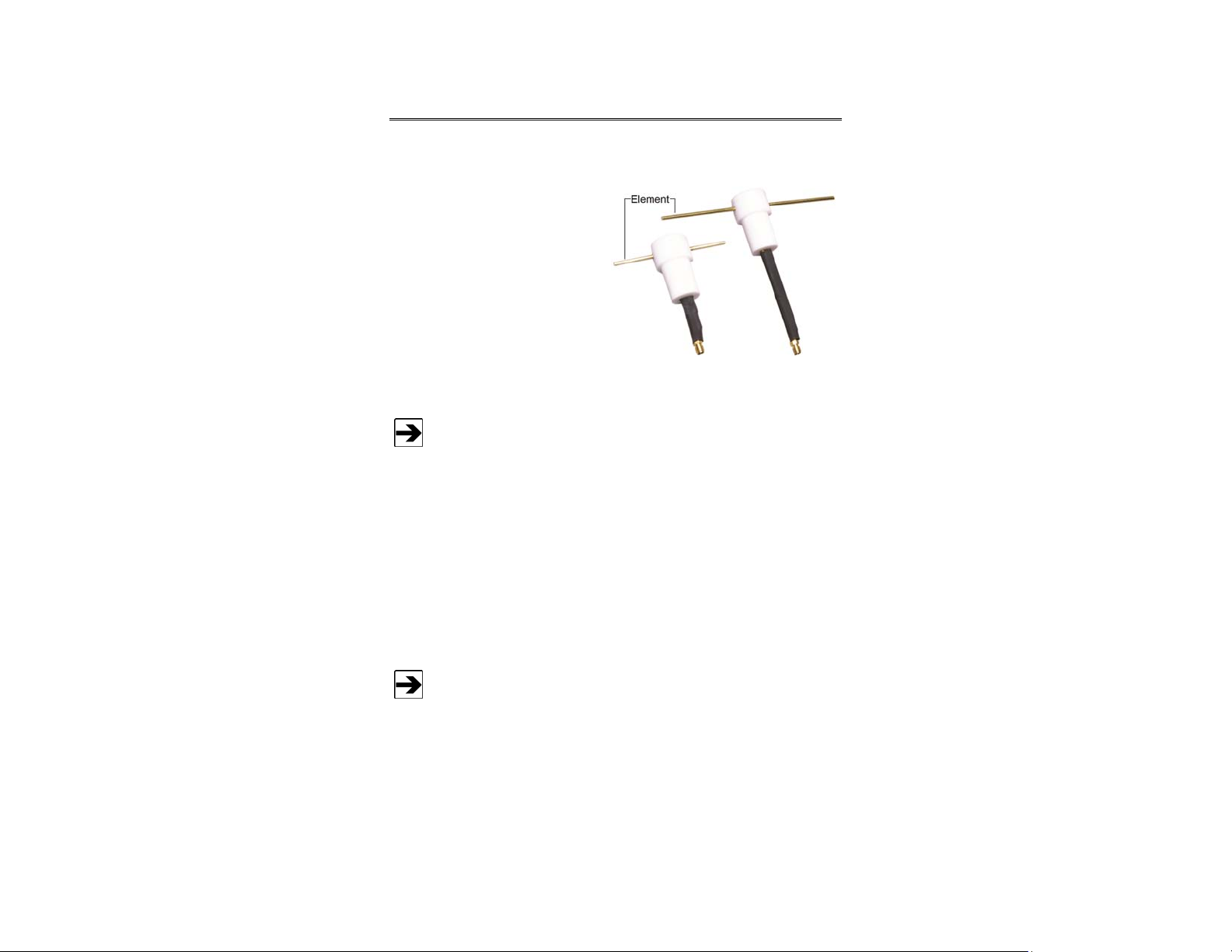
The ETS-Lindgren Model 3125
Series Fixed Length Dipole is a
family of antennas that are tuned to
operate between 440 MHz and
3010 MHz.
The Model 3125 Series is designed
for AAMI/FDA test requirements,
which substitute dipole antennas for
cellular telephones as an emissions
source when testing the
susceptibility of items such as
pacemakers, hearing aids, and
defibrillators.
The most common frequencies in the Model 3125 Series are included
in this manual. Additional frequencies are available; contact
ETS-Lindgren for more information.
The Model 3125 Series antennas are tuned, half-wave length resonant dipoles
with a series-parallel coaxial stub balun. Each antenna has fixed-length dipole
elements mounted in a Teflon® support block. The coaxial balun is terminated
into an SMA receptacle. Individual calibration data is included with each antenna.
An optional bracket is available to mount the Model 3125 Series antenna to an
ETS-Lindgren tripod or other positioning system. See Mounting Instructions on
15 for more information.
page
Use only non-metallic material for any label to be applied to the
Model 3125 Series. Testing has shown that applying a foil-backed
label adversely affects the tuned characteristics of the antenna.
Introduction | 7
Page 8

Tripod Options
ETS-Lindgren offers the following non-metallic, non-reflective tripods for use at
both indoor and outdoor EMC test sites.
• 4-TR Tripod—Constructed of linen
phenolic and delrin, designed with an
adjustable center post for precise height
adjustments. Maximum height is 2.0 m
(80.0 in), and minimum height is 94 cm
(37.0 in). This tripod can support up to
an 11.8 kg (26.0 lb) load.
• 7-TR Tripod—Constructed of PVC and
fiberglass components, providing
increased stability for physically large
antennas. The unique design allows for
quick assembly, disassembly, and
convenient storage. Allows several
different configurations, including options
for manual or pneumatic polarization.
Quick height adjustment and locking
wheels provide ease of use during
testing. Maximum height is 2.17 m
(85.8 in), with a minimum height of 0.8 m
(31.8 in). This tripod can support a
13.5 kg (30 lb) load.
8 | Introduction
Page 9

ETS-Lindgren Product Information Bulletin
See the ETS-Lindgren Product Information Bulletin included with your shipment
for the following:
• Warranty information
• Safety, regulatory, and other product marking information
• Steps to receive your shipment
• Steps to return a component for service
• ETS-Lindgren calibration service
• ETS-Lindgren contact information
Introduction | 9
Page 10

This page intentionally left blank.
10 | Introduction
Page 11

2.0 Maintenance
Before performing any maintenance,
follow the safety information in the
ETS-Lindgren Product Information
Bulletin included with your shipment.
WARRAN TY
Maintenance of the Model 3125 Series is
limited to external components such as
cables or connectors.
If you have any questions concerning
maintenance, contact ETS-Lindgren
Customer Service.
Annual Calibration
See the Product Information Bulletin included with your shipment for information
on ETS-Lindgren calibration services.
Optional Parts
Part Description Part Number
Model 3125 Dipole Mount 106541
Service Procedures
For the steps to return a system or system component to ETS-Lindgren for
service, see the Product Information Bulletin included with your shipment.
Maintenance | 11
Page 12

This page intentionally left blank.
12 | Maintenance
Page 13

3.0 Specifications
Electrical Specifications (Nominal)
Input Impedance: 50 Ω
VSWR: < 1.7:1
Maximum Continuous Power: 1 W
Symmetry: +/- 0.5 dB
Connector: SMA receptacle
Frequency
3125-450 440 MHz–460 MHz
3125-600 590 MHz–610 MHz
3125-870 824 MHz–915 MHz
3125-950 935 MHz–960 MHz
3125-1610 1600 MHz–1620 MHz
3125-1750 1710 MHz–1785 MHz
3125-1840 1805 MHz–1880 MHz
3125-1880 1850 MHz–1910 MHz
3125-2450 2440 MHz–2460 MHz
3125-3000 2990 MHz–3010 MHz
Specifications | 13
Page 14

Physical Specifications
Height Width Depth
3125-450 20.3 cm
8.0 in
3125-600 16.5 cm
6.5 in
3125-870 12.7 cm
5.0 in
3125-950 10.6 cm
4.2 in
3125-1610 8.4 cm
3.3 in
3125-1750 8.1 cm
3.2 in
3125-1840 7.8 cm
3.1 in
3125-1880 7.6 cm
3.0 in
3125-2450 6.1 cm
2.4 in
31.2 cm
12.3 in
23.6 cm
9.3 in
18.2 cm
7.6 in
14.9 cm
5.9 in
8.6 cm
3.4 in
8.4 cm
3.3 in
8.2 cm
3.2 in
8.1 cm
3.1 in
5.5 cm
2.2 in
3.3 cm
1.3 in
3.3 cm
1.3 in
3.3 cm
1.3 in
3.3 cm
1.3 in
3.3 cm
1.3 in
3.3 cm
1.3 in
3.3 cm
1.3 in
3.3 cm
1.3 in
3.3 cm
1.3 in
3125-3000 5.6 cm
2.2 in
14 | Specifications
4.5 cm
1.8 in
3.3 cm
1.3 in
Page 15

4.0 Mounting Instructions
Before connecting any components, follow the safety
information in the ETS-Lindgren Product Information
Bulletin included with your shipment.
The Model 3125 Series antennas are precision
measurement devices. Handle your antenna with
care.
When mounting a Model 3125 Series antenna, limit the material adjacent to
the elements to prevent degradation of antenna performance.
An optional non-metallic mount
(part# 106541) is available for
the Model 3125 Series Fixed
Length Dipole.
The optional mount attaches the
antenna to a tripod or other
positioning system, clamping the
center portion of the support
block.
The mount permits you to easily
adjust the polarity of the
antenna.
Mounting Instructions | 15
Page 16

Following are the steps to use
the optional mount to attach a
Model 3125 Series antenna onto
a tripod or other positioning
system.
1. Slide the shaft of the
antenna through the hole in
the optional mount until the
support block is through the
hole.
16 | Mounting Instructions
Page 17

2. Adjust polarity to the
desired position, and then
insert and tighten the
included nylon screw.
3. Attach the mounting bracket
to a tripod or other
positioning system using
the 1/4–20 hole in the base
of the bracket.
4. Attach a coaxial connector
to the SMA receptacle on
the antenna.
Use a cable of minimal weight to avoid excessive stress on
the antenna.
Mounting Instructions | 17
Page 18

This page intentionally left blank.
18 | Mounting Instructions
Page 19

α
G[dB]/10
5.0 Application
Before connecting any components, follow the
safety information in the ETS-Lindgren
Product Information Bulletin included with your
shipment.
For emissions measurements, electric field strength in db[V/m] is obtained from:
E(dB[V/m])=V(dB[V])+AF(dB[1/m])+ α(dB)
V
= the receiver or spectrum analyzer voltage reading
AF = antenna factor
= cable loss in dB, if cable losses are non-negligible
For immunity testing, the electric field strength generated at a distance d can be
approximated by:
Pg
E
V/m =
()
30
d
d = distance, in meters
g = numeric gain (10
)
P = antenna net input power, in watts
Actual transmitted field strength should be verified using an ETS-Lindgren
electric field probe, or equivalent. In general, closer distances require less power
to create a given field strength.
Application | 19
Page 20

This page intentionally left blank.
20 | Application
Page 21

Appendix A: Warranty
See the Product Information Bulletin included with your shipment for
the complete ETS-Lindgren warranty for your Model 3125 Series.
DURATION OF WARRANTIES FOR MODEL 3125 SERIES
All product warranties, except the warranty of title, and all remedies for warranty
failures are limited to two years.
Product Warranted Duration of Warranty Period
Model 3125 Series
Fixed Length Dipole
2 Years
Warranty | 21
 Loading...