

Page 1
Model 3121D
Adjustable Dipole
User Manual
Page 2

ETS-Lindgren L.P. reserves the right to make changes to any product described
herein in order to improve function, design, or for any other reason. Nothing
contained herein shall constitute ETS-Lindgren L.P. assuming any liability
whatsoever arising out of the application or use of any product or circuit
described herein. ETS-Lindgren L.P. does not convey any license under its
patent rights or the rights of others.
© Copyright 1998–2008 by ETS-Lindgren L.P. All Rights Reserved. No part
of this document may be copied by any means without written permission
from ETS-Lindgren L.P.
Trademarks used in this document: The ETS-Lindgren logo is a trademark of
ETS-Lindgren L.P.
Revision Record | MANUAL 3121 | Part #399041, Rev. D
Revision Description Date
A–C Initial Release; Updates October, 1998–
October, 2000
D Updated content to Model 3121D;
converted to half-size; rebranding
ii |
June, 2008
Page 3

Table of Contents
Notes, Cautions, and Warnings ................................................... v
1.0 Introduction ............................................................................ 7
Tripod Options ...............................................................................................8
ETS-Lindgren Product Information Bulletin ...................................................9
2.0 Maintenance ........................................................................ 11
Annual Calibration .......................................................................................11
Replacement and Optional Parts.................................................................11
Service Procedures .....................................................................................12
3.0 Specifications....................................................................... 13
Electrical Specifications ............................................................................... 13
Physical Specifications ................................................................................13
Element Length Frequency Chart................................................................14
4.0 Assembly Instructions .......................................................... 17
5.0 Mounting Instructions........................................................... 21
Using Included Mounting Adapters..............................................................21
Using the Stinger Mount ..............................................................................23
Additional Mounting Options........................................................................24
4-TR Mounting Options........................................................................24
7-TR and Mast Mounting Options........................................................ 25
2x2 Boom Mounting Options ...............................................................26
6.0 Typical Data ......................................................................... 27
Model 3121D DB-1 Typical Data .................................................................27
Model 3121D DB-1 Gain......................................................................27
Model 3121D DB-1 Antenna Factor.....................................................28
Model 3121D DB-1 Typical Balun Loss ...............................................29
Model 3121D DB-2 Typical Data .................................................................30
Model 3121D DB-2 Gain......................................................................30
Model 3121D DB-2 Antenna Factor.....................................................31
Model 3121D DB-2 Typical Balun Loss ...............................................32
| iii
Page 4

Model 3121D DB-3 Typical Data .................................................................33
Model 3121D DB-3 Gain......................................................................33
Model 3121D DB-3 Antenna Factor.....................................................34
Model 3121D DB-3 Typical Balun Loss ...............................................35
Model 3121D DB-4 Typical Data .................................................................36
Model 3121D DB-4 Gain......................................................................36
Model 3121D DB-4 Antenna Factor.....................................................37
Model 3121D DB-4 Typical Balun Loss ...............................................38
Appendix A: Warranty ................................................................ 39
iv |
Page 5
Notes, Cautions, and Warnings
Note: Denotes helpful information intended to
See the ETS-Lindgren Product Information Bulletin for safety,
regulatory, and other product marking information.
provide tips for better use of the product.
Caution: Denotes a hazard. Failure to follow
instructions could result in minor personal injury
and/or property damage. Included text gives proper
procedures.
Warning: Denotes a hazard. Failure to follow
instructions could result in SEVERE personal injury
and/or property damage. Included text gives proper
procedures.
| v
Page 6

This page intentionally left blank.
vi |
Page 7
1.0 Introduction
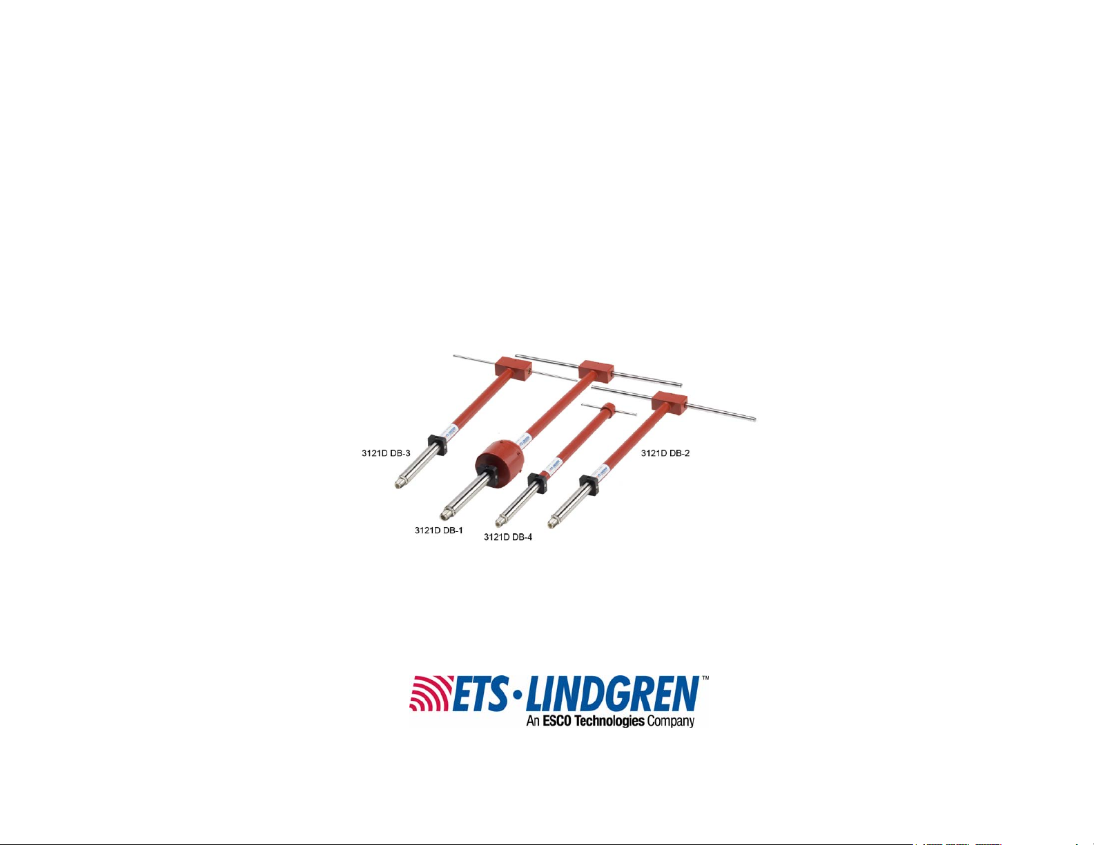
The ETS-Lindgren Model 3121D
Adjustable Dipole Antenna System is
designed to operate over the 30 MHz to
1 GHz frequency range for
measurements to meet military, DOD,
VDE, and FCC EME measurement
specifications.
3121D DB-1
The Model 3121D includes the DB-1, DB-2, DB-3, and DB-4 antennas.
The antennas are lightweight and sturdily
constructed for portability and
ruggedness. A carrying case supplied
with the antenna set allows for organized
storage and access to all antenna
components. Also included is a
measuring tape for adjusting the dipole
elements to frequency.
3121D DB-2
The dipole elements are made from
nickel-plated brass extension elements
with four special extension rods for
operation at the lowest frequencies. Each
set of elements is designed to be
mounted into a particular balun.
3121D DB-3
Introduction | 7
Page 8
The elements for baluns can be
extended to dipole lengths above and
below the specified frequency of each
particular balun. The elements should be
used with the specified balun and should
not be adjusted to frequencies beyond
the specified range of each balun. This is
to prevent errors in calibration of the
antenna receiving system.
A variety of mounting options are available for the Model 3121D. For information,
see Mounting Instructions on page 21.
Tripod Options
ETS-Lindgren offers the following nonmetallic, non-reflective tripods for use at
both indoor and outdoor EMC test sites.
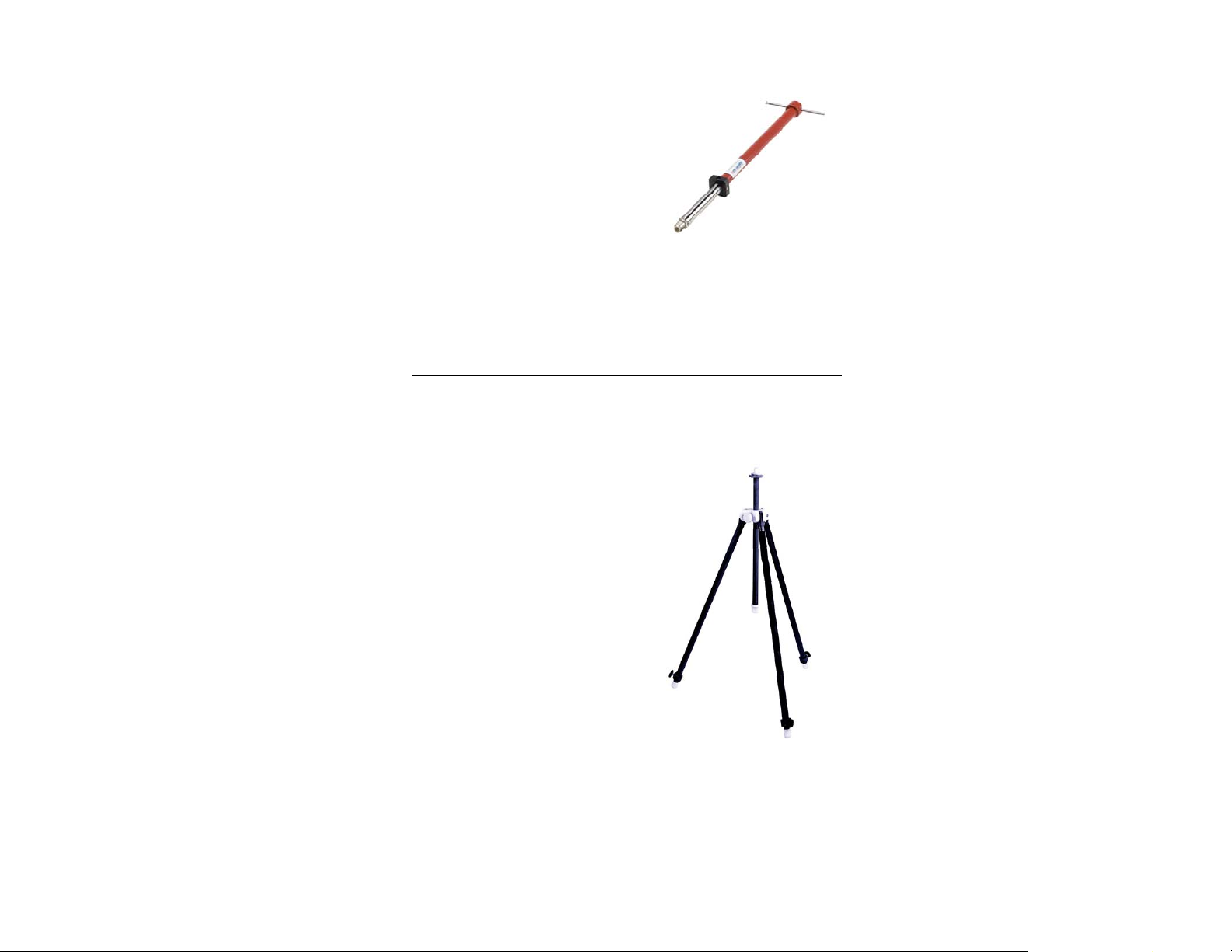
• Model 4-TR—Constructed of linen
phenolic and delrin, designed with an
adjustable center post for precise
height adjustments. Maximum height
is 2.0 m (80.0 in), and minimum height
is 94 cm (37.0 in). This tripod can
support up to an 11.8 kg (26.0 lb)
load.
3121D DB-4
8 | Introduction
Page 9
• Model 7-TR—Constructed of PVC
and fiberglass components, providing
increased stability for physically large
antennas. The unique design allows
for quick assembly, disassembly, and
convenient storage. Allows several
different configurations, including
options for manual or pneumatic
polarization. Quick height adjustment
and locking wheels provide ease of
use during testing. Maximum height is
2.17 m (85.8 in), with a minimum
height of .8 m (31.8 in). This tripod
can support a 13.5 kg (30 lb) load.
ETS-Lindgren Product Information Bulletin
See the ETS-Lindgren Product Information Bulletin included with your shipment
for the following:
• Warranty information
• Safety, regulatory, and other product marking information
• Steps to receive your shipment
• Steps to return a component for service
• ETS-Lindgren calibration service
• ETS-Lindgren contact information
Introduction | 9
Page 10

This page intentionally left blank.
10 | Introduction
Page 11
2.0 Maintenance
Before performing any maintenance, follow
the safety information in the ETS-Lindgren
Product Information Bulletin included with
your shipment.
WARRANT Y
Maintenance of the Model 3121D is limited
to external components such as cables or
connectors.
If you have any questions concerning
maintenance, contact ETS-Lindgren
Customer Service.
Annual Calibration
See the Product Information Bulletin included with your shipment for information
on ETS-Lindgren calibration services.
Replacement and Optional Parts
Following are the part numbers for ordering replacement or optional parts for the
Model 3121D Adjustable Dipole Antenna System.
Available For 3121D Model:
Part Description
DB-1 DB-2 DB-3 DB-4
Element, Low Frequency (2) √ √ 3121LE
Part
Number
Element, Medium Frequency
(2)
Element Extension,
19.5 inches (4)
Carrying Case √ √ √ √ 3121CASE
√ 3121EE
Maintenance | 11
√ 3121ME
Page 12
Available For 3121D Model:
Part Description
DB-1 DB-2 DB-3 DB-4
Clamp Block √ √ √ √ 102108
Support Base √ √ √ √ 101942B
Support Rod √ √ √ √ 100733
For additional/optional mounting hardware, see Additional Mounting
Options on page 24.
Part
Number
Service Procedures
For the steps to return a system or system component to ETS-Lindgren for
service, see the Product Information Bulletin included with your shipment.
12 | Maintenance
Page 13

3.0 Specifications
Electrical Specifications
Frequency Range (Overall): 30 MHz–1 GHz
DB-1: 30 MHz–60 MHz
DB-2: 60 MHz–140 MHz
DB-3: 140 MHz–400 MHz
DB-4: 400 MHz–1 GHz
Impedance: Matched to 50 Ω
Maximum Length: 17 ft
Maximum Power Handling
Capability:
VSWR Ratio (Average): < 1.6:1
Peak Power: NA
Typical Balun Loss: See Typical Data on page 27
50 W
Physical Specifications
Model 3121D
DB-1 DB-2 DB-3 DB-4
Length: 26.87 in
68.25 cm
Width:
Minimum
Maximum
Weight: 2.37 lb
16.50 in
41.91 cm
168.00 in
426.72 cm
1.07 kg
22.00 in
55.88 cm
16.50 in
41.91 cm
129.00 in
327.66 cm
1.69 lb
0.76 kg
20.50 in
52.07 cm
14.00 in
35.56 cm
49.00 in
124.46
1.50 lb
0.68 kg
19.25 in
48.89 cm
5.50 in
13.97 cm
18.00 in
45.72 cm
0.87 lb
0.39 kg
Specifications | 13
Page 14

Element Length Frequency Chart
Frequency
(MHz)
28 2577 130 540
29 2488 135 520
30 2412 140 502
31 2340 145 484
32 2272 155 453
34 2167 160 439
35 2073 165 425
36 2013 170 413
37 1954 175 401
38 1899 180 390
39 1848 190 370
40 1802 200 351
42 1713 210 334
44 1634 220 319
46 1561 230 305
Single Element
Length (mm)
Frequency
(MHz)
Single Element
Length (mm)
48 1494 240 293
50 1434 250 281
55 1304 260 270
60 1194 270 260
65 1103 280 250
70 1022 290 241
75 951 300 234
80 887 310 226
85 836 320 219
14 | Specifications
Page 15

Frequency
(MHz)
90 788 330 212
95 747 340 206
100 710 350 200
105 676 360 195
110 646 370 190
115 616 380 185
120 590 390 180
125 565 400 175
Single Element
Length (mm)
Frequency
(MHz)
Single Element
Length (mm)
Specifications | 15
Page 16

This page intentionally left blank.
16 | Specifications
Page 17

4.0 Assembly Instructions
Before connecting any components, follow the
safety information in the ETS-Lindgren
Product Information Bulletin included with your
shipment.
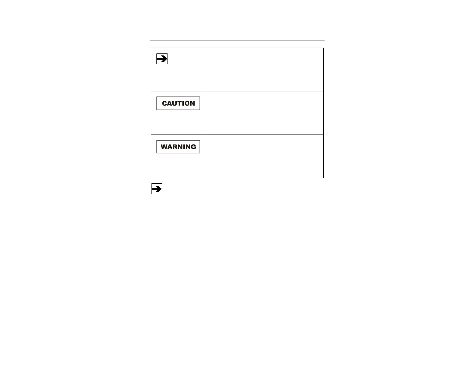
1. Choose a balun that meets the desired frequency.
2. On baluns DB-1, DB-2, and DB-3, insert the proper elements; the DB-4
is shipped with the elements inserted.
3121D DB-1
Assembly Instructions | 17
Page 18

3121D DB-2
3121D DB-3
18 | Assembly Instructions
Page 19

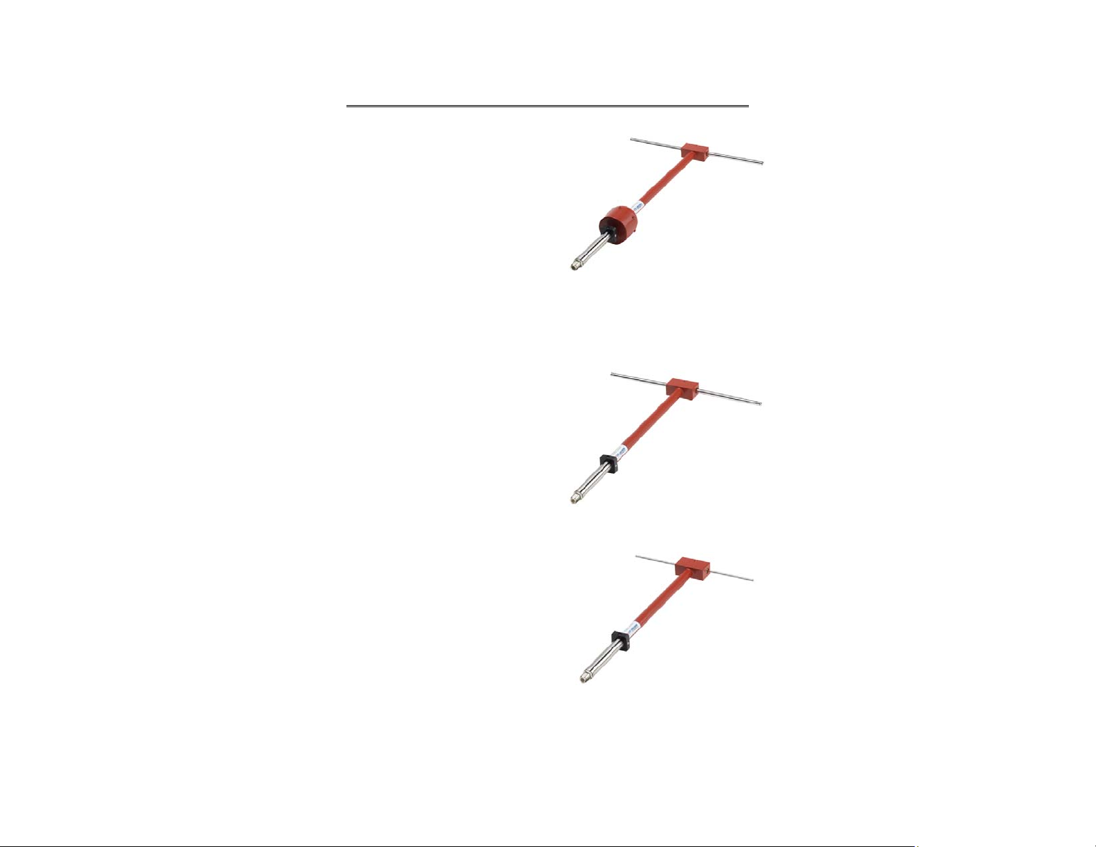
3121D DB-4
3. Balun DB-1 requires the use of two extension rods on each leg of the
dipole. Attach the longest collapsible elements to the extension rods.
4. Place the balun in the tripod clamp and extend the elements to proper
length as specified by the Element Length Frequency Chart on
page 14. See Mounting Instructions on page 21 for the steps to mount
the Model 3121D Adjustable Dipole Antenna System.
This method is used for baluns DB-1, DB-2, and DB-3. At frequencies
above 400 MHz, balun DB-4 should be used and the dipole length
adjusted as specified on the engraved plastic ruler.
Typical Data on page 27 provides the factors in dB which should be added to the
receiver or spectrum analyzer reading in (dBuV) to calculate the field strength in
dBuV/Meter.
Assembly Instructions | 19
Page 20

This page intentionally left blank.
20 | Assembly Instructions
Page 21

5.0 Mounting Instructions
Before connecting any components, follow the
safety information in the ETS-Lindgren
Product Information Bulletin included with your
shipment.
Using Included Mounting Adapters
The Model 3121D Adjustable Dipole Antenna System ships with these mounting
adapters:
• 102108 Clamp Block—Uses standard
7/8–14 threads and comes with a 1/4–20
thread adapter for mounting to an
ETS-Lindgren tripod or most other
tripods.
• 101942B Support Base
• 100733 Support Rod
Mounting Instructions | 21
Page 22

To use these adapters to mount the Model 3121D to a 4-TR tripod:
3121D DB-1
3121D DB-2,
3121D DB-3,
3121 DB-4
1. Assemble the clamp block, support base, and support rod, and attach
the support base to the 4-TR tripod.
2. Unscrew the clamp block latch and open the top.
3. Insert the balun into the clamp block and close the top over the balun.
4. Move the latch to the closed position and tighten so the balun is held
securely.
5. Attach the cable to the output connector on the antenna.
22 | Mounting Instructions
Page 23

Using the Stinger Mount
The stinger on the Model 3121D enables you to mount to antenna directly to an
ETS-Lindgren 7-TR Tripod Positioner.
Additional hardware is required to use the stinger to mount the
Model 3121D to a mast. For information on ordering optional mounting
hardware, contact the ETS-Lindgren Sales Department.
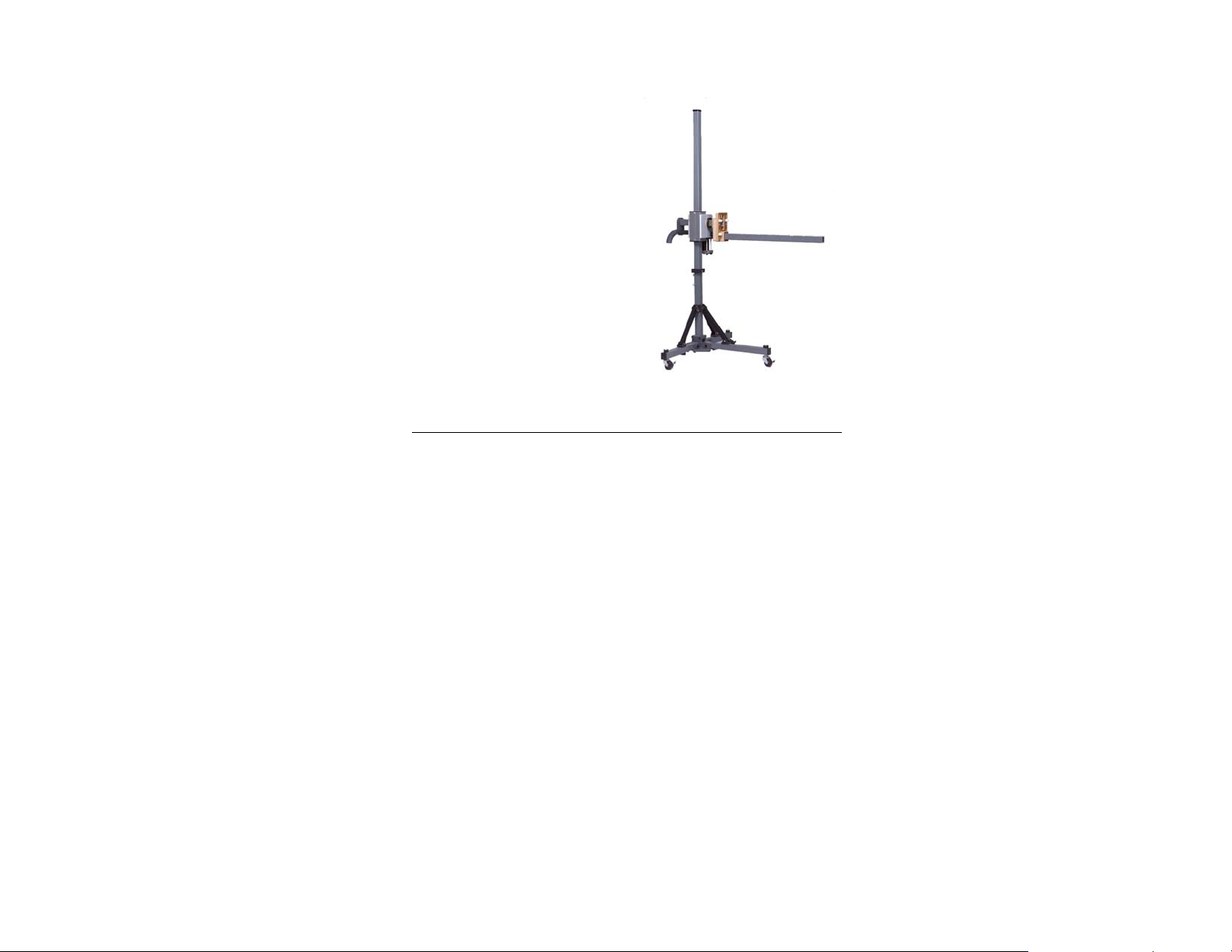
Shown stinger-mounted onto a 7-TR
Do not use the stinger to mount the Model 3121D onto a 4-TR tripod.
Mounting Instructions | 23
Page 24

Additional Mounting Options
4-TR MOUNTING OPTIONS
Following are additional options for mounting the Model 3121D onto an
ETS-Lindgren 4-TR tripod. Contact the ETS-Lindgren Sales Department for
information on ordering optional mounting hardware.
24 | Mounting Instructions
Page 25

7-TR AND MAST MOUNTING OPTIONS
The stinger on the Model 3121D enables you to mount to antenna directly to an
ETS-Lindgren 7-TR Tripod Positioner. Following are additional options for
mounting the Model 3121D onto an ETS-Lindgren 7-TR Tripod Positioner.
Contact the ETS-Lindgren Sales Department for information on ordering optional
mounting hardware.
Mast refers to 2070 Series, 2075, and 2175 Antenna Towers.
7-TR refers to 109042, 106328, and 108197 booms:
• 109042 boom—Straight boom; for general antenna mounting on a
7-TR
• 106328 boom—Offset boom; for general antenna mounting on a
7-TR with pneumatic or manual polarization
• 108197 boom—Center rotate boom; for rear-mount stinger-type
antennas only
Mounting Instructions | 25
Page 26

2X2 BOOM MOUNTING OPTIONS
Following are additional options for mounting the Model 3121D onto a 2x2 boom.
Contact the ETS-Lindgren Sales Department for information on ordering optional
mounting hardware.
2x2 boom refers to a typical 2-inch by 2-inch boom.
26 | Mounting Instructions
Page 27

6.0 Typical Data
Model 3121D DB-1 Typical Data
MODEL 3121D DB-1 GAIN
Typical Data | 27
Page 28

MODEL 3121D DB-1 ANTENNA FACTOR
28 | Typical Data
Page 29

MODEL 3121D DB-1 TYPICAL BALUN LOSS
Typical Data | 29
Page 30

Model 3121D DB-2 Typical Data
MODEL 3121D DB-2 GAIN
30 | Typical Data
Page 31

MODEL 3121D DB-2 ANTENNA FACTOR
Typical Data | 31
Page 32

MODEL 3121D DB-2 TYPICAL BALUN LOSS
32 | Typical Data
Page 33

Model 3121D DB-3 Typical Data
MODEL 3121D DB-3 GAIN
Typical Data | 33
Page 34

MODEL 3121D DB-3 ANTENNA FACTOR
34 | Typical Data
Page 35

MODEL 3121D DB-3 TYPICAL BALUN LOSS
Typical Data | 35
Page 36

Model 3121D DB-4 Typical Data
MODEL 3121D DB-4 GAIN
36 | Typical Data
Page 37

MODEL 3121D DB-4 ANTENNA FACTOR
Typical Data | 37
Page 38

MODEL 3121D DB-4 TYPICAL BALUN LOSS
38 | Typical Data
Page 39

Appendix A: Warranty
See the Product Information Bulletin included with your shipment for
the complete ETS-Lindgren warranty for your Model 3121D Adjustable
Dipole Antenna System.
DURATION OF WARRANTIES FOR MODEL 3121D
All product warranties, except the warranty of title, and all remedies for warranty
failures are limited to two years.
Product Warranted Duration of Warranty Period
Model 3121D Adjustable Dipole
Antenna System
2 Years
Warranty | 39
 Loading...