

Page 1
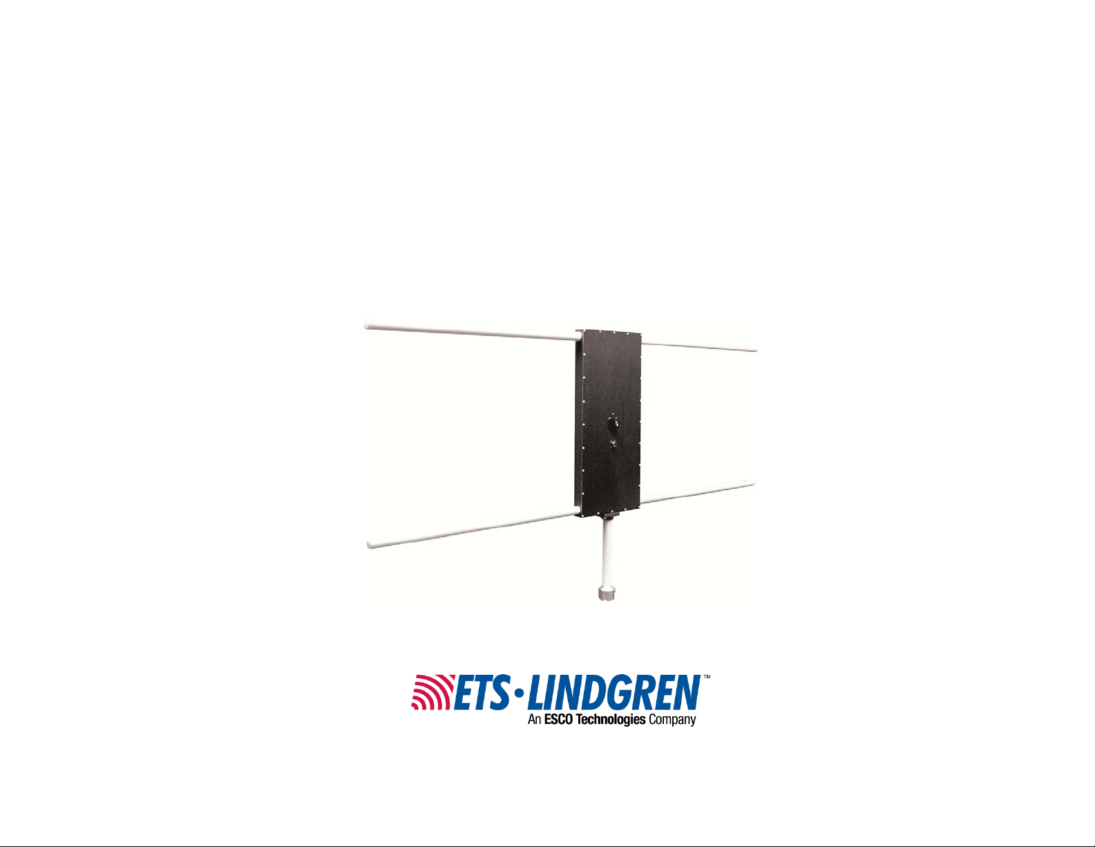
Model 3107B
Parallel Element
E-Field Generator
User Manual
Page 2
ETS-Lindgren L.P. reserves the right to make changes to any product described
herein in order to improve function, design, or for any other reason. Nothing
contained herein shall constitute ETS-Lindgren L.P. assuming any liability
whatsoever arising out of the application or use of any product or circuit
described herein. ETS-Lindgren L.P. does not convey any license under its
patent rights or the rights of others.
© Copyright 1991–2011 by ETS-Lindgren L.P. All Rights Reserved. No part
of this document may be copied by any means without written permission
from ETS-Lindgren L.P.
Trademarks used in this document: The ETS-Lindgren logo is a trademark of
ETS-Lindgren L.P.
Revision Record | MANUAL,3107B | Part #399036, Rev. C
Revision Description Date
A Initial Release January, 1991
B Edits/updates December, 1998
C Rebrand February, 2011
ii |
Page 3

Table of Contents
Notes, Cautions, and Warnings ................................................ v
1.0 Introduction .......................................................................... 7
Tripod Options ............................................................................................... 8
ETS-Lindgren Product Information Bulletin ................................................... 9
2.0 Maintenance ....................................................................... 11
Replacement and Optional Parts ................................................................. 11
Service Procedures ..................................................................................... 11
3.0 Specifications ..................................................................... 13
Electrical Specifications ............................................................................... 13
Physical Specifications (Assembled) ........................................................... 13
Typical Power Requirements at One-Meter ................................................. 14
Typical Test Setup: Power Requirements ........................................... 15
Typical Input Voltage Requirements at One-Meter ...................................... 16
Typical Test Setup: Input Voltage Requirements ................................ 17
Schematic for Model 3107B ......................................................................... 18
4.0 Assembly and Operation .................................................. 19
Appendix A: Warranty ............................................................. 21
| iii
Page 4

This page intentionally left blank.
iv |
Page 5
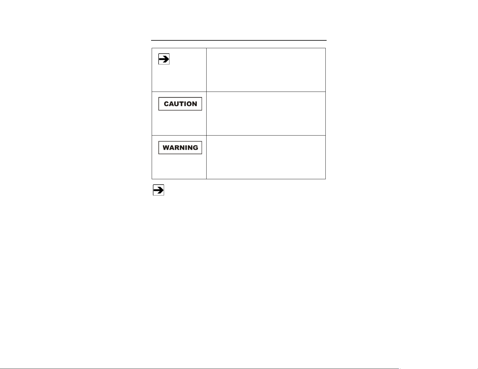
Notes, Cautions, and Warnings
Note: Denotes helpful information intended to
See the ETS-Lindgren Product Information Bulletin for safety,
regulatory, and other product marking information.
provide tips for better use of the product.
Caution: Denotes a hazard. Failure to follow
instructions could result in minor personal injury
and/or property damage. Included text gives proper
procedures.
Warning: Denotes a hazard. Failure to follow
instructions could result in SEVERE personal injury
and/or property damage. Included text gives proper
procedures.
| v
Page 6

This page intentionally left blank.
vi |
Page 7
1.0 Introduction
The wide band design of the ETS-Lindgren Model 3107B Parallel Element
E-Field Generator allows operation over the entire 10 kHz to 30 MHz
frequency range in two bands: Band 1 covers the frequency range from
10 kHz to 5 MHz, and Band 2 covers 5 MHz to 30 MHz.
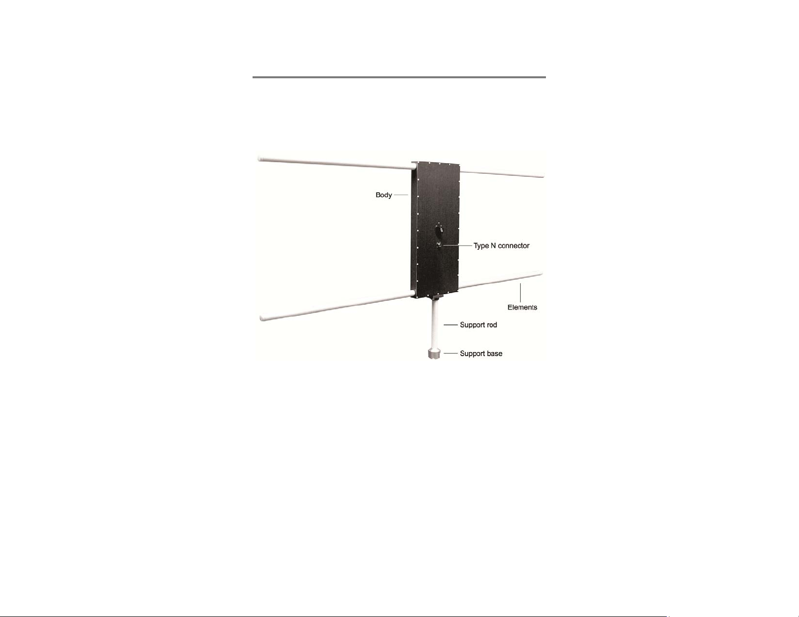
For portability, the Model 3107B elements are easily attached and removed.
Attach each the element by rotating it clockwise into the Model 3107B body until
it is firmly connected; to disassemble, rotate each element counterclockwise.
Introduction | 7
Page 8

Tripod Options
The Model 3107B includes a tripod mount that can be attached to a standard
tripod. ETS-Lindgren offers the following non-metallic, non-reflective tripods for
use at both indoor and outdoor EMC test sites.
• 4-TR Tripod—Constructed of linen
phenolic and delrin, designed with an
adjustable center post for precise height
adjustments. Maximum height is 2.0 m
(80.0 in), and minimum height is 94 cm
(37.0 in). This tripod can support up to
an 11.8 kg (26.0 lb) load.
• 7-TR Tripod—Constructed of PVC and
fiberglass components, providing
increased stability for physically large
antennas. The unique design allows for
quick assembly, disassembly, and
convenient storage. Allows several
different configurations, including options
for manual or pneumatic polarization.
Quick height adjustment and locking
wheels provide ease of use during
testing. Maximum height is 2.17 m
(85.8 in), with a minimum height of 0.8 m
(31.8 in). This tripod can support a
13.5 kg (30 lb) load.
8 | Introduction
Page 9

ETS-Lindgren Product Information Bulletin
See the ETS-Lindgren Product Information Bulletin included with your shipment
for the following:
• Warranty information
• Safety, regulatory, and other product marking information
• Steps to receive your shipment
• Steps to return a component for service
• ETS-Lindgren calibration service
• ETS-Lindgren contact information
Introduction | 9
Page 10

This page intentionally left blank.
10 | Introduction
Page 11

2.0 Maintenance
Before performing any maintenance,
follow the safety information in the
ETS-Lindgren Product Information
Bulletin included with your shipment.
WARRANTY
Maintenance of the Model 3107B is
limited to external components such as
cables or connectors.
If you have any questions concerning
maintenance, contact ETS-Lindgren
Customer Service.
Replacement and Optional Parts
ETS-Lindgren may substitute a similar part or new part number with
the same functionality for another part/part number. Contact
ETS-Lindgren for questions about part numbers and ordering parts.
Following are the part numbers for ordering replacement or optional parts for the
Model 3107B.
Part Description Part Number
Support Rod 101948
Support Base 101942B
Service Procedures
For the steps to return a system or system component to ETS-Lindgren for
service, see the Product Information Bulletin included with your shipment.
Maintenance | 11
Page 12

This page intentionally left blank.
12 | Maintenance
Page 13

3.0 Specifications
Electrical Specifications
Frequency Range: 10 kHz–30 MHz
• Band 1: 10 kHz–5 MHz
• Band 2: 5 MHz–30 MHz
Input Impedance: 50 Ohms
Field Pattern: At one meter on centerline the field
is a linearly polarized, essentially
homogenous E-field.
E-Field Capability: See tables on page 14 and page 16.
Maximum Power Capability: 1000 Watts
Connector: Type N
Physical Specifications (Assembled)
Length: 184.15 cm (72.5 in)
Width (Element Separation): 60.96 cm (24.0 in)
Height: 5.08 cm (2.0 in)
Weight: 5.44 kg (12.0 lb)
Specifications | 13
Page 14

Typical Power Requirements at One-Meter
See typical test setup on page 15.
14 | Specifications
Page 15

T
YPICAL TEST SETUP: POWER REQUIREMENTS
Specifications | 15
Page 16

Typical Input Voltage Requirements at One-Meter
See typical test setup on page 17.
16 | Specifications
Page 17

T
YPICAL TEST SETUP: INPUT VOLTAGE REQUIREMENTS
Specifications | 17
Page 18

Schematic for Model 3107B
18 | Specifications
Page 19

4.0 Assembly and Operation
1. Attach the support rod to the mounting plate on the bottom of the
Model 3107B Parallel Element E-Field Generator by rotating it
clockwise into the plate until it is firmly connected.
2. Attach the support base to the support rod by rotating it clockwise onto
the rod until it is firmly connected.
3. Attach the Model 3107B assembly to a standard tripod (not included)
by rotating the support base clockwise onto the connector on the
tripod.
Assembly and Operation | 19
Page 20

4. Attach the signal source to the Type N connector on the Model 3107B.
Use a voltage monitor or power monitor at the signal source to
determine the input voltage/power applied. The field strength capability
is shown in the tables on page 14 and page 16. A field intensity
monitor on the opposite side of the Model 3l07B from the test sample
and at the corresponding distance will give a good approximation of
the field seen by the sample.
20 | Assembly and Operation
Page 21

Appendix A: Warranty
See the Product Information Bulletin included with your shipment for
the complete ETS-Lindgren warranty for your Model 3107B.
DURATION OF WARRANTIES FOR MODEL 3107B
All product warranties, except the warranty of title, and all remedies for warranty
failures are limited to one year.
Product Warranted Duration of Warranty Period
Model 3107B Parallel Element
Field Generator
1 Year
Warranty | 21
 Loading...