

Page 1
Model 3104C
Biconical Antenna
User Manual
Page 2

ETS-Lindgren L.P. reserves the right to make changes to any product described
herein in order to improve function, design, or for any other reason. Nothing
contained herein shall constitute ETS-Lindgren L.P. assuming any liability
whatsoever arising out of the application or use of any product or circuit
described herein. ETS-Lindgren L.P. does not convey any license under its
patent rights or the rights of others.
© Copyright 2000–2009 by ETS-Lindgren L.P. All Rights Reserved. No part
of this document may be copied by any means without written permission
from ETS-Lindgren L.P.
Trademarks used in this document: The ETS-Lindgren logo is a trademark of
ETS-Lindgren L.P.
Revision Record | MANUAL 3104C | Part #399034, Rev. F
Revision Description Date
A–D Initial Release; updates / edits 2000–2002
E Updated Specifications September, 2002
F Updated PX branding; updated
Mounting Instructions; rebrand
ii |
February, 2009
Page 3

Table of Contents
Notes, Cautions, and Warnings ................................................ v
1.0 Introduction .......................................................................... 7
Optional Items ................................................................................................ 7
Portable Elements (Model 3104CP) ...................................................... 7
Extended Portable Elements (Model 3104CPX) ................................... 8
Carrying Cases ...................................................................................... 8
Tripod Options ....................................................................................... 8
ETS-Lindgren Product Information Bulletin ................................................... 9
2.0 Maintenance ....................................................................... 11
Annual Calibration ....................................................................................... 11
Service Procedures ..................................................................................... 11
3.0 Specifications ..................................................................... 13
Electrical Specifications ............................................................................... 13
Physical Specifications ................................................................................ 13
4.0 Assembly Instructions ...................................................... 15
5.0 Mounting Instructions ....................................................... 17
Using Included Mounting Adapters on a 4-TR ............................................. 17
Additional Mounting Options ........................................................................ 19
4-TR Mounting Options........................................................................ 19
7-TR and Mast Mounting Options ........................................................ 20
2x2 Boom Mounting Options ............................................................... 21
6.0 Operation ............................................................................ 23
7.0 Typical Data ........................................................................ 25
Model 3104C Antenna Factor ...................................................................... 25
Model 3104C Gain ....................................................................................... 26
Model 3104C VSWR .................................................................................... 27
Model 3104C Half-Power Beamwidth .......................................................... 28
Model 3104C Forward Power ...................................................................... 29
@ 1 M–Derived from AF ...................................................................... 29
@ 3 M–Derived from AF ...................................................................... 30
@ 3M–Measured over Conducting Ground ......................................... 31
| iii
Page 4

Appendix A: Warranty ............................................................. 33
iv |
Page 5
Notes, Cautions, and Warnings
Note: Denotes helpful information intended to
See the ETS-Lindgren Product Information Bulletin for safety,
regulatory, and other product marking information.
provide tips for better use of the product.
Caution: Denotes a hazard. Failure to follow
instructions could result in minor personal injury
and/or property damage. Included text gives proper
procedures.
Warning: Denotes a hazard. Failure to follow
instructions could result in SEVERE personal injury
and/or property damage. Included text gives proper
procedures.
| v
Page 6

This page intentionally left blank.
vi |
Page 7
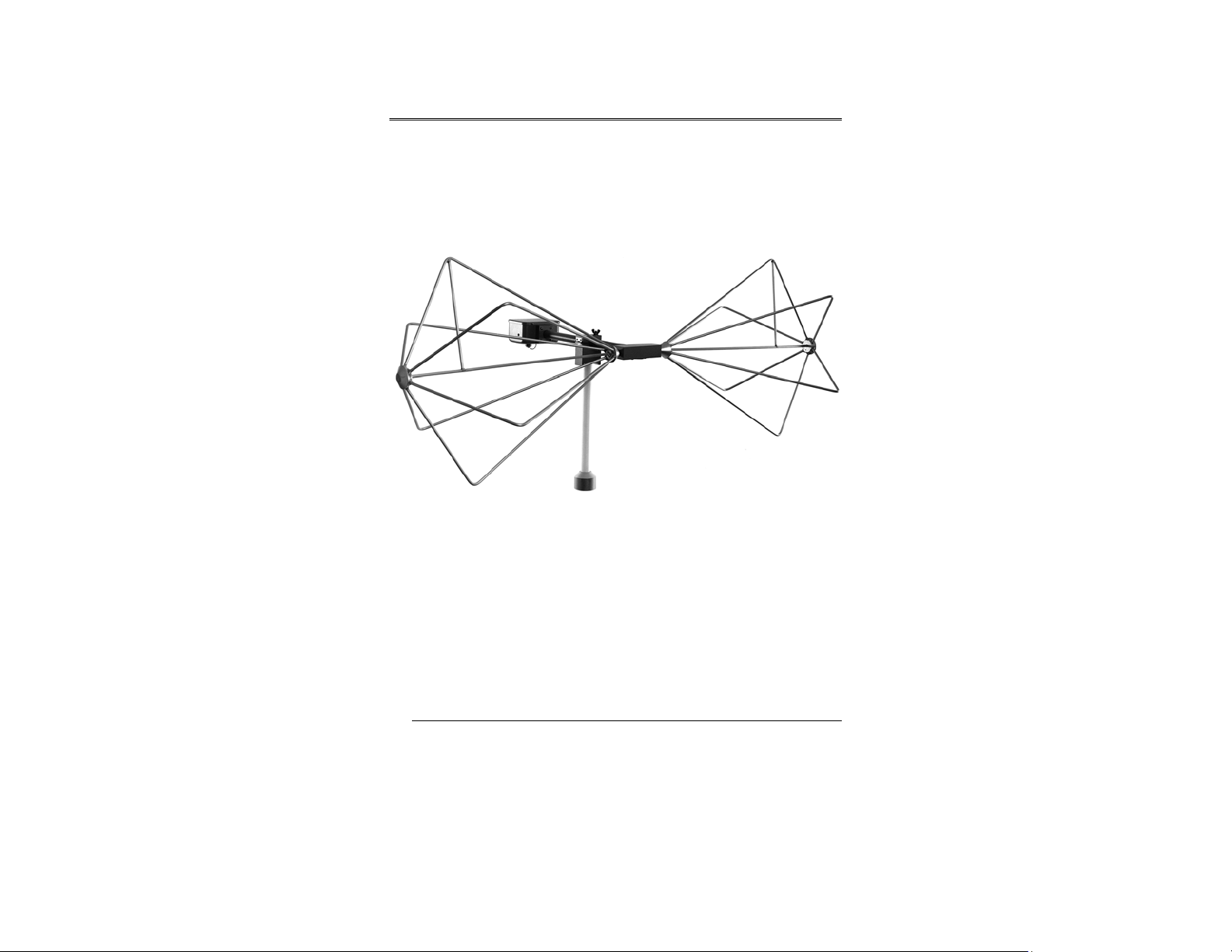
1.0 Introduction
The ETS-Lindgren Model 3104C Biconical Antenna is designed to operate
over the 20 MHz to 200 MHz frequency range to meet Military and Department of
Defense EMI specifications. The Model 3104C is designed and precisely
manufactured to conform to the requirements of MIL-STD-461 and other Military
Standards as reflected in Drawing ES-F-201286.
The biconical elements are made from welded aluminum. The elements mount in
a balun network fabricated of phenolic and equipped with the necessary
impedance-matching components. The lightweight construction provides easy
handling and storage.
Each antenna is individually calibrated during the manufacturing process. The
results of these calibrations are included for use in specification compliance
testing.
Optional Items
PORTABLE ELEMENTS (MODEL 3104CP)
Collapsible folding elements are available, making the Model 3104C portable and
ideal for field use. Both the standard rigid and optional folding elements attach to
the balun using screw mounts. This makes changing between the two types of
elements quick and easy.
Introduction | 7
Page 8

EXTENDED PORTABLE ELEMENTS (MODEL 3104CPX)
An extended version of the portable element is available. These folding elements
are twice as long as the standard elements. The longer elements enable you to
generate high fields at low frequencies with reduced applied power.
CARRYING CASES
Carrying cases for biconical antennas and portable elements are available.
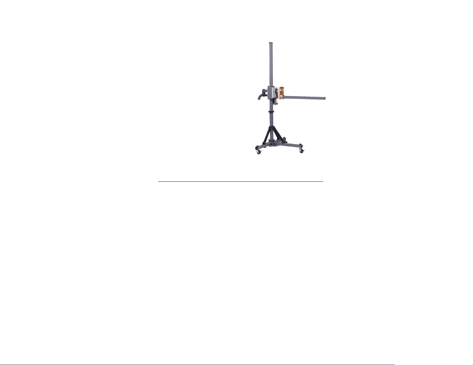
TRIPOD OPTIONS
ETS-Lindgren offers the following nonmetallic, non-reflective tripods for use at
both indoor and outdoor EMC test sites.
• 4-TR Tripod—Constructed of linen
phenolic and delrin, designed with an
adjustable center post for precise height
adjustments. Maximum height is 2.0 m
(80.0 in), and minimum height is 94 cm
(37.0 in). This tripod can support up to
an 11.8 kg (26.0 lb) load.
8 | Introduction
Page 9
• 7-TR Tripod—Constructed of PVC and
fiberglass components, providing
increased stability for physically large
antennas. The unique design allows for
quick assembly, disassembly, and
convenient storage. Allows several
different configurations, including options
for manual or pneumatic polarization.
Quick height adjustment and locking
wheels provide ease of use during
testing. Maximum height is 2.17 m
(85.8 in), with a minimum height of .8 m
(31.8 in). This tripod can support a
13.5 kg (30 lb) load.
ETS-Lindgren Product Information Bulletin
See the ETS-Lindgren Product Information Bulletin included with your shipment
for the following:
• Warranty information
• Safety, regulatory, and other product marking information
• Steps to receive your shipment
• Steps to return a component for service
• ETS-Lindgren calibration service
• ETS-Lindgren contact information
Introduction | 9
Page 10

This page intentionally left blank.
10 | Introduction
Page 11

2.0 Maintenance
Before performing any maintenance,
follow the safety information in the
ETS-Lindgren Product Information
Bulletin included with your shipment.
WARRANT Y
Maintenance of the Model 3104C is
limited to external components such as
cables or connectors.
If you have any questions concerning
maintenance, contact ETS-Lindgren
Customer Service.
Annual Calibration
See the Product Information Bulletin included with your shipment for information
on ETS-Lindgren calibration services.
Service Procedures
For the steps to return a system or system component to ETS-Lindgren for
service, see the Product Information Bulletin included with your shipment.
Maintenance | 11
Page 12

This page intentionally left blank.
12 | Maintenance
Page 13

3.0 Specifications
Electrical Specifications
Frequency Range: 20 MHz–200 MHz
Impedance: Matched to 50 Ω
VSWR Ratio (Average): 2.8:1
Power Input Capability:
Connector: Type N
• 50 Watts continuous power
• 100 Watts short-term peak power
Physical Specifications
Length: 143.5 cm (56.5 in)
Depth: 81.3 cm (32 in)
Diameter: 53.3 cm (21 in)
Weight: 2.7 kg (6.0 lb)
Specifications | 13
Page 14

This page intentionally left blank.
14 | Specifications
Page 15

4.0 Assembly Instructions
Before connecting any components, follow the
safety information in the ETS-Lindgren
Product Information Bulletin included with your
shipment.
The Model 3104C Biconical Antenna is shipped unassembled, and includes
these parts:
• Balun
• Biconical element (2)
• Belleville washer (2)
• 100733 Support Rod
• 101942B Support Base
• 102108 Clamp Block
Assembly Instructions | 15
Page 16

To assemble the Model 3104C:
1. Slide a belleville washer onto the threaded screw end of one of the
biconical elements.
2. Line up the screw threads with the receptacle hole on the balun and
turn the biconical element until it is firmly secured in the balun.
Do not cross thread this connection or
permanent damage to the joint could occur.
3. Repeat step 1 and step 2 using the remaining washer and biconical
element.
16 | Assembly Instructions
Page 17

5.0 Mounting Instructions
Before connecting any components, follow the
safety information in the ETS-Lindgren
Product Information Bulletin included with your
shipment.
Using Included Mounting Adapters on a 4-TR
The Model 3104C ships with the following adapters, used to mount the antenna
to a 4-TR tripod:
• 102108 Clamp Block—Uses
standard 7/8–14 threads and comes
with a 1/4–20 thread adapter for
mounting to an ETS-Lindgren tripod
or most other tripods.
• 100733 Support Rod
• 101942B Support Base
Mounting Instructions | 17
Page 18

To use these adapters to mount the Model 3104C to a 4-TR tripod:
1. Assemble the clamp block, support base, and support rod.
2. Attach the support base to the 4-TR tripod.
3. Unscrew the clamp block latch and open the top.
4. Insert the shaft of the balun into the clamp block and close the top.
5. Move the latch to the closed position and tighten so the antenna is held
securely.
6. Attach the cable to the output connector on the antenna.
18 | Mounting Instructions
Page 19

Additional Mounting Options
4-TR MOUNTING OPTIONS
Following are additional options for mounting the Model 3104C onto an
ETS-Lindgren 4-TR Tripod. Contact the ETS-Lindgren Sales Department for
information on ordering optional mounting hardware.
Mounting Instructions | 19
Page 20

7-TR AND MAST MOUNTING OPTIONS
Following are options for mounting the Model 3104C onto an ETS-Lindgren 7-TR
Tripod or mast.
Contact the ETS-Lindgren Sales Department for information on ordering optional
mounting hardware.
Mast refers to 2070 Series, 2075, and 2175 Antenna Towers.
7-TR refers to 109042, 106328, and 108197 booms:
• 109042 boom—Straight boom; for general antenna mounting on a
7-TR
• 106328 boom—Offset boom; for general antenna mounting on a
7-TR with pneumatic or manual polarization
• 108197 boom—Center rotate boom; for rear-mount stinger-type
antennas only
20 | Mounting Instructions
Page 21

2X2 BOOM MOUNTING OPTIONS
Following are additional options for mounting the Model 3104C onto a 2x2 boom.
Contact the ETS-Lindgren Sales Department for information on ordering optional
mounting hardware.
2x2 boom refers to a typical 2-inch by 2-inch boom.
Mounting Instructions | 21
Page 22

This page intentionally left blank.
22 | Mounting Instructions
Page 23

6.0 Operation
The Model 3104C Biconical Antenna has a traditional coaxial wound balun that
provides a broad frequency range and moderate gain for both transmitting and
receiving. This antenna may be used for radiated immunity measurements
provided that the peak input power is limited to no more than 100 W.
For enhanced measurement repeatability it is recommended that when the
Model 3104C is used vertically the same element orientation be maintained from
measurement to measurement. A white strip or dimples on the element block
mark the coax shield side of the element. Keep this side towards ground when
the antenna is used vertically to increase test repeatability, especially when the
Model 3104C is used inside a shielded enclosure.
Operation | 23
Page 24

This page intentionally left blank.
24 | Operation
Page 25

7.0 Typical Data
Model 3104C Antenna Factor
Typical Data | 25
Page 26

Model 3104C Gain
26 | Typical Data
Page 27

Model 3104C VSWR
Typical Data | 27
Page 28

Model 3104C Half-Power Beamwidth
28 | Typical Data
Page 29

Model 3104C Forward Power
@ 1 M–DERIVED FROM AF
Typical Data | 29
Page 30

@ 3 M–DERIVED FROM AF
30 | Typical Data
Page 31

@ 3M–MEASURED OVER CONDUCTING GROUND
Typical Data | 31
Page 32

This page intentionally left blank.
32 | Typical Data
Page 33

Appendix A: Warranty
See the Product Information Bulletin included with your shipment for
the complete ETS-Lindgren warranty for your Model 3104C.
DURATION OF WARRANTIES FOR MODEL 3104C
All product warranties, except the warranty of title, and all remedies for warranty
failures are limited to two years.
Product Warranted Duration of Warranty Period
Model 3104C Biconical Antenna 2 Years
Warranty | 33
 Loading...