

Page 1

Model 3100 Series
Conical Log Spiral
Antennas
User Manual
Page 2

ii
www.ets-lindgren.com
ETS-Lindgren Inc. reserves the right to make changes to any product described
herein in order to improve function, design, or for any other reason. Nothing
contained herein shall constitute ETS-Lindgren Inc. assuming any liability
whatsoever arising out of the application or use of any product or circuit
described herein. ETS-Lindgren Inc. does not convey any license under its
patent rights or the rights of others.
© Copyright 2002–2013 by ETS-Lindgren Inc. All Rights Reserved. No part
of this document may be copied by any means without written permission
from ETS-Lindgren Inc.
Trademarks used in this document: The ETS-Lindgren logo is a trademark of
ETS-Lindgren Inc.
Revision Record | MANUAL,3101,3102,3103 | Part #399276, Rev. C
Revision
Description
Date
A
Initial Release
September, 2002
B
Updated Gain chart for Model 3101;
rebrand
July, 2008
C
Updated illustrations in Circular
Polarization
March, 2013
Page 3

www.ets-lindgren.com
iii
Table of Contents
Notes, Cautions, and Warnings ................................................ v
1.0 Introduction .......................................................................... 7
Standard Configuration ............................................................................... 7
Optional Items ............................................................................................ 8
Right-Hand Circular Polarization ......................................................... 8
Tripod Options .................................................................................... 8
ETS-Lindgren Product Information Bulletin ................................................. 9
2.0 Maintenance ....................................................................... 11
Maintenance Recommendations ............................................................... 11
Annual Calibration .................................................................................... 11
Replacement and Optional Parts .............................................................. 12
Service Procedures .................................................................................. 12
3.0 Specifications ..................................................................... 13
Electrical Specifications ............................................................................ 13
Physical Specifications ............................................................................. 13
4.0 Mounting Instructions ....................................................... 15
Using Included Mounting Adapters ........................................................... 15
Model 3101 ....................................................................................... 16
Model 3102 ....................................................................................... 17
Model 3103 ....................................................................................... 18
5.0 Circular Polarization .......................................................... 19
Left-Hand Circular Polarization ................................................................. 19
Right-Hand Circular Polarization ............................................................... 20
6.0 Typical Data ........................................................................ 21
Model 3101 ............................................................................................... 21
Model 3101 Antenna Factor .............................................................. 21
Model 3101 Gain .............................................................................. 22
Model 3101 VSWR ........................................................................... 22
Model 3101 Forward Power – 1 Meter .............................................. 23
Model 3102 ............................................................................................... 24
Model 3102 Antenna Factor .............................................................. 24
Page 4

iv
www.ets-lindgren.com
Model 3102 Gain .............................................................................. 24
Model 3102 VSWR ........................................................................... 25
Model 3102 Forward Power – 1 Meter .............................................. 25
Model 3103 ............................................................................................... 26
Model 3103 Antenna Factor .............................................................. 26
Model 3103 Gain .............................................................................. 26
Model 3103 VSWR ........................................................................... 27
Model 3103 Forward Power – 1 Meter .............................................. 27
Appendix A: Warranty ............................................................. 29
Page 5
www.ets-lindgren.com
v
Notes, Cautions, and Warnings
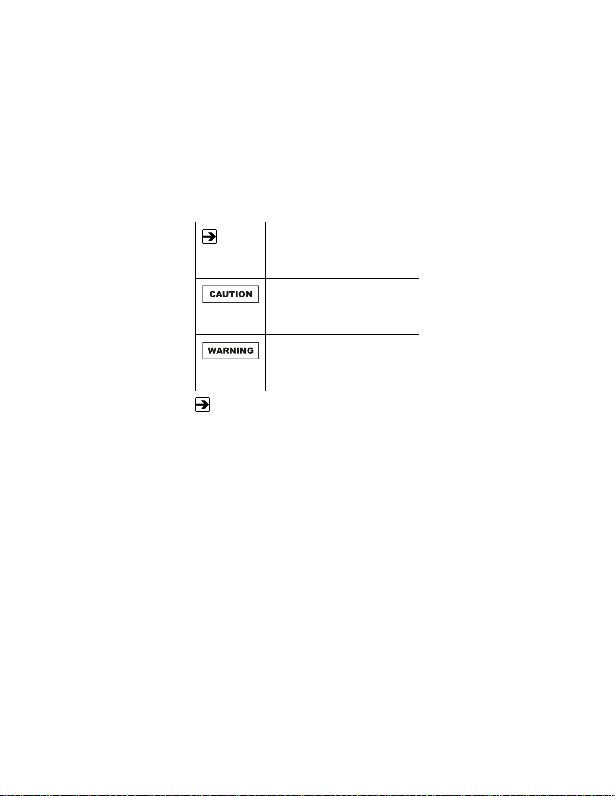
Note: Denotes helpful information intended to
provide tips for better use of the product.
Caution: Denotes a hazard. Failure to follow
instructions could result in minor personal injury
and/or property damage. Included text gives proper
procedures.
Warning: Denotes a hazard. Failure to follow
instructions could result in SEVERE personal injury
and/or property damage. Included text gives proper
procedures.
See the ETS-Lindgren Product Information Bulletin for safety,
regulatory, and other product marking information.
Page 6

vi
www.ets-lindgren.com
This page intentionally left blank.
Page 7

www.ets-lindgren.com
Introduction
7
1.0 Introduction
The ETS-Lindgren Model 3100 Series Conical Log Spiral antennas are
circularly polarized broadband antennas covering the frequency range of
100 MHz to 10 GHz. This family of antennas includes the Model 3101,
Model 3102, and the Model 3103. The Conical Log Spiral antennas are designed
specifically for EMI measurements and compliance testing as called for in various
Military Standards.
Each antenna is constructed of a fiberglass cone upon which two logarithmic
spirals of 50-ohm coaxial cable are securely fastened. Outside windings improve
heat dissipation. The coaxial connectors are located in the phenolic base plate of
the cone. A 1/4–20 adapter for a tripod or other mounting configuration is
attached to the antenna near its horizontal center of gravity or at the antenna
base plate.
The Conical Log Spiral antennas receive both circular polarized and linear
polarized fields (with a 3-dB variance for linear fields) under normal operating
conditions.
Model 3101, Model 3102, and Model 3103 are right-hand wound, and transmit
and receive a left-hand circularly polarized wave. Model 3101L, Model 3102L,
and Model 3103L are left-hand wound, and transmit and receive a right-hand
circularly polarized wave.
During the manufacturing process each antenna is individually calibrated at
1 meter per SAE ARP 958. Typical antenna data is included beginning on
page 21. Actual factors and a signed Certificate of Calibration Conformance are
shipped with each antenna.
Standard Configuration
Left-hand circular polarization
Support rod
Support base configured to accept ETS-Lindgren or other tripod mount
with standard 1/4–20 threads
Page 8
8
Introduction
www.ets-lindgren.com
Optional Items
RIGHT-HAND CIRCULAR POLARIZATION
This option reverses the antenna windings for right-hand polarization.
See Circular Polarization on page 19.
TRIPOD OPTIONS
ETS-Lindgren offers the following nonmetallic, non-reflective tripods for use at
both indoor and outdoor EMC test sites.
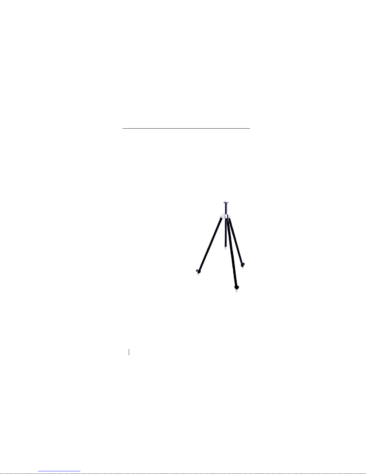
4-TR Tripod—Constructed of linen
phenolic and delrin, designed with an
adjustable center post for precise height
adjustments. Maximum height is 2.0 m
(80.0 in), and minimum height is 94 cm
(37.0 in). This tripod can support up to
an 11.8 kg (26.0 lb) load.
Page 9
www.ets-lindgren.com
Introduction
9
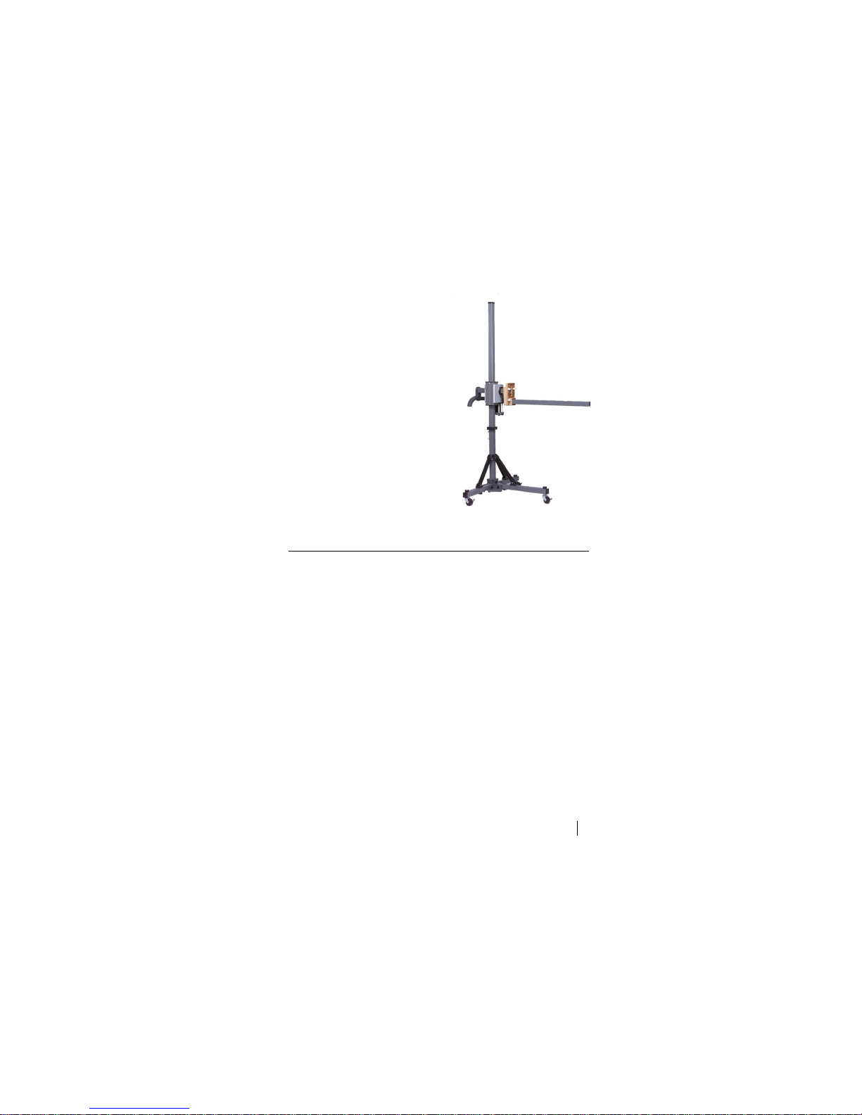
7-TR Tripod—Constructed of PVC and
fiberglass components, providing
increased stability for physically large
antennas. The unique design allows for
quick assembly, disassembly, and
convenient storage. Allows several
different configurations, including options
for manual or pneumatic polarization.
Quick height adjustment and locking
wheels provide ease of use during
testing. Maximum height is 2.17 m
(85.8 in), with a minimum height of 0.8 m
(31.8 in). This tripod can support a
13.5 kg (30 lb) load.
ETS-Lindgren Product Information Bulletin
See the ETS-Lindgren Product Information Bulletin included with your shipment
for the following:
Warranty information
Safety, regulatory, and other product marking information
Steps to receive your shipment
Steps to return a component for service
ETS-Lindgren calibration service
ETS-Lindgren contact information
Page 10

10
Introduction
www.ets-lindgren.com
This page intentionally left blank.
Page 11

www.ets-lindgren.com
Maintenance
11
2.0 Maintenance
Before performing any maintenance, follow
the safety information in the ETS-Lindgren
Product Information Bulletin included with
your shipment.
WARRANTY
Maintenance of the Conical Log Spiral
antennas is limited to external components
such as cables or connectors.
If you have any questions concerning
maintenance, contact ETS-Lindgren
Customer Service.
Maintenance Recommendations
If the Conical Log Spiral antennas are used outdoors, periodically check them for
water accumulation. Water has a high dielectric constant and can alter the
performance of the antenna.
Annual Calibration
See the Product Information Bulletin included with your shipment for information
on ETS-Lindgren calibration services.
Page 12

12
Maintenance
www.ets-lindgren.com
Replacement and Optional Parts
Following are the part numbers for ordering replacement and optional parts for
the Model 3100 Series Conical Log Spiral antennas.
Part Description
Part Number
Right-hand wound / left-hand circularly polarized wave:
Model 3101 :
3101
Model 3102 :
3102
Model 3103 :
3103
Left-hand wound / right-hand circularly polarized wave:
Model 3101 :
3101L
Model 3102 :
3102L
Model 3103 :
3103L
Support Base
(for all Model 3100 Series antennas)
101942B
Model 3101Support Rod
101941
Model 3102 Support Rod
101943B
Model 3103 Support Rod
101944
Service Procedures
For the steps to return a system or system component to ETS-Lindgren for
service, see the Product Information Bulletin included with your shipment.
Page 13

www.ets-lindgren.com
Specifications
13
3.0 Specifications
Electrical Specifications
Model 3101
Model 3102
Model 3103
Frequency
Range:
200 MHz–1 GHz
1 GHz–10 GHz
100 MHz–1 GHz
Impedance:
50 Ω
50 Ω
50 Ω
VSWR
(Avg):
2.4:1
1.6:1
1.9:1
Maximum
Continuous
Power:
100 Watts
50 Watts
100 Watts
Short-Term
Peak Power:
150 watts
100 Watts
150 Watts
Polarization:
Circular
Connector:
Type N female
Physical Specifications
Model 3101
Model 3102
Model 3103
Length:
81.3 cm
32.0 in
38.1 cm
15.0 in
102.0 cm
40.0 in
Diameter:
33.0 cm
13.0 in
12.7 cm
5.0 in
66.0 cm
26.0 in
Weight:
4.5 kg
10.0 lb
3.6 kg
8.0 lb
10.0 kg
22.0 lb
Page 14

14
Specifications
www.ets-lindgren.com
This page intentionally left blank.
Page 15

www.ets-lindgren.com
Mounting Instructions
15
4.0 Mounting Instructions
Before connecting any components, follow the
safety information in the ETS-Lindgren
Product Information Bulletin included with your
shipment.
Do not mount the Model 3100 Series Conical
Log Spiral antennas onto a 2x2 boom.
Using Included Mounting Adapters
The Model 3100 Series Conical Log Spiral antennas ship with these mounting
adapters:
101942B Support Base—Ships
with all Model 3100 Series antennas
Support Rod
101941 Support Rod—Ships
with Model 3101
101943B Support Rod—Ships
with Model 3102
101944 Support Rod—Ships
with Model 3103
Page 16

16
Mounting Instructions
www.ets-lindgren.com
MODEL 3101
To use the included adapters to mount the Model 3101 to a 4-TR Tripod, a
7-TR Tripod, or a mast:
Do not cross thread any connections or permanent could occur.
1. Thread the support
rod into the support
base.
2. Thread the other end
of the support rod
into the mounting
block on the
antenna.
3. Attach the support base to the 4-TR, 7-TR, or mast.
Page 17

www.ets-lindgren.com
Mounting Instructions
17
MODEL 3102
To use the included adapters to mount the Model 3101 to a 4-TR Tripod, a
7-TR Tripod, or a mast:
Do not cross thread any connections or permanent could occur.
1. Align the through holes
on the support rod with
the back plate of the
antenna.
2. Insert the mounting screws (included) into the through holes and back plate.
Tighten to secure the rod into place. Do not over tighten.
3. Attach the support base to the 4-TR, 7-TR, or mast.
Page 18

18
Mounting Instructions
www.ets-lindgren.com
MODEL 3103
To use the included adapters to mount the Model 3101 to a 4-TR Tripod, a
7-TR Tripod, or a mast:
Do not cross thread any connections or permanent could occur.
1. Thread the support
rod into the support
base.
2. Thread the other end
of the support rod
into the mounting
block on the
antenna.
3. Attach the support base to the 4-TR, 7-TR, or mast.
Page 19

www.ets-lindgren.com
Circular Polarization
19
5.0 Circular Polarization
Left-Hand Circular Polarization
Page 20

20
Circular Polarization
www.ets-lindgren.com
Right-Hand Circular Polarization
Page 21

www.ets-lindgren.com
Typical Data
21
6.0 Typical Data
Typical data measurements taken at one-meter spacing.
Model 3101
MODEL 3101 ANTENNA FACTOR
Page 22

22
Typical Data
www.ets-lindgren.com
MODEL 3101 GAIN
MODEL 3101 VSWR
Page 23

www.ets-lindgren.com
Typical Data
23
MODEL 3101 FORWARD POWER – 1 METER
Page 24

24
Typical Data
www.ets-lindgren.com
Model 3102
MODEL 3102 ANTENNA FACTOR
MODEL 3102 GAIN
Page 25

www.ets-lindgren.com
Typical Data
25
MODEL 3102 VSWR
MODEL 3102 FORWARD POWER – 1 METER
Page 26

26
Typical Data
www.ets-lindgren.com
Model 3103
MODEL 3103 ANTENNA FACTOR
MODEL 3103 GAIN
Page 27

www.ets-lindgren.com
Typical Data
27
MODEL 3103 VSWR
MODEL 3103 FORWARD POWER – 1 METER
Page 28

28
Typical Data
www.ets-lindgren.com
This page intentionally left blank.
Page 29

www.ets-lindgren.com
Warranty
29
Appendix A: Warranty
See the Product Information Bulletin included with your shipment for
the complete ETS-Lindgren warranty for your Conical Log Spiral
antennas.
DURATION OF WARRANTIES FOR CONICAL LOG SPIRAL ANTENNAS
All product warranties, except the warranty of title, and all remedies for warranty
failures are limited to two years.
Product Warranted
Duration of Warranty Period
Model 3100 Series Conical Log
Spiral Antennas
2 Years
 Loading...