

Page 1
Turntable
Model 2188
1.2m, 1.5m and 2.0m
Users Manual
©ETS-Lindgren—January, 2006 Rev. B—Part#399771
Page 2
Model 2188 Turntable
ETS-Lindgren reserves the right to make changes to any products herein to improve functioning
or design. Although the information in this document has been carefully reviewed and is believed
to be reliable, ETS-Lindgren does not assume any liability arising out of the application or use of
any product or circuit described herein; nor does it convey any license under its patent rights nor
the rights of others.
©Copyright 2006 by ETS-Lindgren L.P. All Rights Reserved. No part of this document may be
copied by any means without written permission from ETS-Lindgren L.P.
Revision Description Date
A Initial Release November, 2005
B Added two meter turntable information, updated
January, 2006
illustrations and drawings
E-Mail & Internet Addresses
support@ets-lindgren.com
http://www.ets-lindgren.com
USA
1301 Arrow Point Drive, Cedar Park, TX 78613 USA
P O Box 80589, Austin, TX 78708-0589 USA
Tel. +512.531.6400
Fax +512.531.6500
Finland
Mekaanikontie 1, 27510, Eura, Finland
Tel. +358.2.838.330
Fax +358.2.865.1233
Japan
4-2-6, Kohinata
Bunkyo-ku, Tokyo 112-0006 Japan
Tel. +81.3.3813.7100
Fax +81.3.3813.8068
China
1917-1918 Xue Zhixuan Building
No. 16 Xue Qing Road
Haidian District
Beijing Postcode: 100083 China
Tel. +86.010.827.55304
Fax +86.010.827.55307
2
©ETS-Lindgren—January, 2006
Rev. B—P#399771
Page 3

Model 2188 Turntable
Table of Contents
1. Introduction.................................................................................................................................. 7
1.1. Standard Configuration......................................................................................................... 7
1.2. Model 2188 Options..............................................................................................................8
1.2.1. Model 2090 Series Positioning Controller...................................................................... 8
1.2.2. Additional Fiber Optic Cable .......................................................................................... 9
2. Getting Started........................................................................................................................... 11
2.1. Unpacking and Acceptance................................................................................................ 11
2.2. Electrical Specifications......................................................................................................11
2.2.1........................................................................................................................................ 11
2.2.2. Mechanical ...................................................................................................................12
2.3. Turntable Installation Considerations ................................................................................. 12
2.3.1. Conduit......................................................................................................................... 12
2.3.2. Electrical Considerations.............................................................................................. 12
2.3.3. Access.......................................................................................................................... 12
3. Installation.................................................................................................................................. 13
3.1. Tools Required.................................................................................................................... 13
3.2. Unpacking........................................................................................................................... 14
3.3. Positioning the Turntable.................................................................................................... 14
3.4. Installing Anchor Plates ...................................................................................................... 16
3.5. Raised Panel Floor Flange Installation............................................................................... 17
3.6. Floor Flange Mounting in a Concrete Pit............................................................................ 18
3.7. Motorbase Attachment........................................................................................................19
3.8. Final Leveling of the Table.................................................................................................. 20
3.9. Application of Conductive Grease ...................................................................................... 20
4. Electrical Installation.................................................................................................................. 21
5. Operation................................................................................................................................... 23
5.1. Editing Positioning Controller Configuration Parameters ................................................... 23
5.2. Setting Travel Limits ........................................................................................................... 24
5.3. Turntable Encoder Calibration............................................................................................ 25
5.3.2. Turntable Calibration Example..................................................................................... 26
5.4. Changing Rotation Speed................................................................................................... 27
5.5. Variable Speed Settings ..................................................................................................... 27
5.6. Speed Selection..................................................................................................................28
5.7. GPIB Commands................................................................................................................ 29
6. Infrared Controller...................................................................................................................... 31
7. Recommended Maintenance..................................................................................................... 33
7.1. Routine Maintenance.......................................................................................................... 33
7.2. Bi-Annual Maintenance.......................................................................................................33
7.3. Annual Maintenance........................................................................................................... 34
8. Warranty.................................................................................................................................... 37
9. Addendum A: Drawings............................................................................................................39
©ETS-Lindgren—January, 2006
Rev. B—P#399771
3
Page 4
Model 2188 Turntable
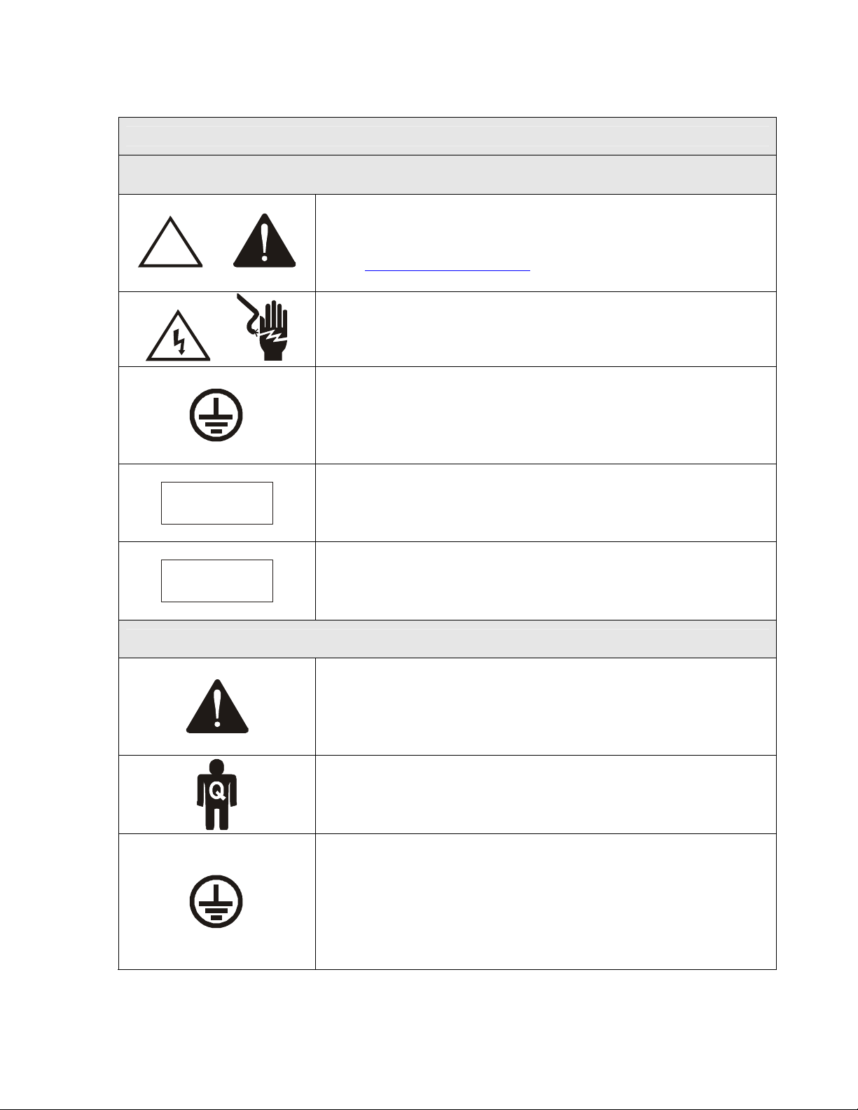
SAFETY SYMBOL DEFINITIONS
NOTICE: This product and related documentation must be reviewed for familiarization
with safety markings and instructions prior to operation of the product.
REFER TO MANUAL—When the product is marked with
this symbol refer to the instruction manual for additional
!
OR
OR
CAUTION
WARNING
information. If the instruction manual has been misplaced,
go to www.ets-lindgren.com
contact ETS-Lindgren customer service.
HIGH VOLTAGE—Indicates the presence of hazardous
voltage. Unsafe practice could result in several personal
injury or death.
PROTECTIVE EARTH GROUND (SAFETY GROUND)—
Indicates protective earth terminal. Uninterruptible safety
earth ground from the main power source to the product
input wiring terminals, power cord or supplied power cord
set shall be provided.
CAUTION—Denotes a hazard. Failure to follow
instructions could result in minor personal injury and/or
property damage. Text that follows the symbol will provide
proper procedures.
WARNING—Denotes a hazard. Failure to follow instruction
could result in SEVERE personal injury and/or property
damage. Text that follows the symbol will provide proper
procedures.
for downloadable files or
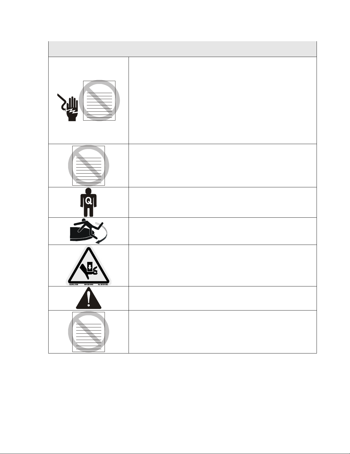
GENERAL SAFETY CONSIDERATIONS/PRECAUTIONS
Read this manual completely before beginning the
installation of the turntable. Refer to drawings at the rear of
the manual and the “Tools Required” list included prior to
4
beginning installation. This equipment should be installed
and operated only by qualified personnel.
The electrical installation of this product should be
accomplished by an individual who is authorized to so do by
the appropriate local authority. The installation should be in
compliance with local electrical safety codes.
BEFORE POWER IS APPLIED TO THIS INSTRUMENT,
GROUND IT PROPERLY through the protective conductor
of the AC power cable to a power source provided with
protective earth contact. Any interruption of the protective
(grounding) conductor, inside or outside of the instrument,
or disconnection of the protective earth terminal could result
in personal injury.
©ETS-Lindgren—January, 2006
Rev. B—P#399771
Page 5
Model 2188 Turntable
GENERAL SAFETY CONSIDERATIONS/PRECAUTIONS (continued)
BEFORE SERVICING: CONTACT ETS-LINDGREN
(+1.512.531.6400)—servicing or modifying the unit without
ETS-Lindgren authorization may void your warranty. If an
WARRAN TY
attempt to service the unit must be made, disconnect all
electrical power prior to beginning. Voltages exist at many
points within the instrument that could, if contacted, cause
personal injury. Only trained service personnel should
perform adjustments and/or service procedures upon this
instrument. Capacitors inside this instrument may still be
CHARGED even when the instrument is disconnected from
the power source.
WARRAN TY
Do not make any modifications to this unit without
consulting the factory directly.
ONLY QUALIFIED PERSONNEL should operate or service
this equipment.
STAY CLEAR of moving components during operation of
equipment. Do not operate the turntable while someone is
physically on the turntable top.
Do not, at any time, place hands or feet in the vicinity of the
drive pinion on the turntable.
Regularly inspect all equipment and conduct scheduled
maintenance in accordance with the factory
WARRAN TY
recommendations provided.
Only use replacement parts and fasteners ordered directly
from the factory.
©ETS-Lindgren—January, 2006
Rev. B—P#399771
5
Page 6

Model 2188 Turntable
This page intentionally left blank.
6
©ETS-Lindgren—January, 2006
Rev. B—P#399771
Page 7

Model 2188 Turntable
1. Introduction
The ETS-Lindgren Model 2188 is an electric-powered, variable-speed
turntable platform system designed for use with an EMCO Model 2090
series positioning controller to perform EMI compliance testing. The Model
2188 is available in 1.2-meter, 1.5-meter and 2.0-meter diameters. The
turntable is ideal for installations in new or existing test locations where pit
excavation is not an option or must be shallow.
The top of the turntable is conductive with a continuous ground brush to
electrically couple it to the ground plane. The ground brushes are attached
directly to the chamber floor via the floor flange and are in continuous
contact with the turntable top. The brushes point downward from the floor
flange. .
The drive motor and gearing are located beneath the platform. The Model
2188 turntable is powered by an electric motor through a worm gear box
with a chain and sprocket final drive. The top of the turntable is removable
to provide easy access in the event that service is required. The
electronics are located in a shielded enclosure. Signal I/O is via fiber-optic
cable.
To prevent over-travel of the turntable in either direction of movement,
“hard” limits are provided in the form of pins that actuate switches located
below the tabletop. These pins allow limits to be set and allow as much as
two full rotations. Rotation speed can be varied from the front panel of the
controller or through the IEEE-488 interface bus.
1.1. Standard Configuration
• Turntable Assembly
• Single-phase electric drive (208-230 VAC 50/60 Hz)
• Variable speed drive
• Conductive top
• Continuous rotation
• One (1) ten meter fiber-optic control cable
• Fiber optic shield penetration kit
• Two (2) fiber optic feed-thrus
• One (1) three meter fiber optic control cable
©ETS-Lindgren—January, 2006
Rev. B—P#399771
7
Page 8

Model 2188 Turntable
1.2. Model 2188 Options
1.2.1. Model 2090 Series Positioning Controller
The Model 2090 Series Multi-Device Positioning Controller is
designed for use with ETS-Lindgren positioning devices
such as antenna towers, turntables, reverberation paddles,
multi-axis positioners, etc. to accomplish a variety of tests for
EMC compliance, antenna pattern measurements, and
more.
The Controller allows the user to synchronize the
simultaneous, yet independent movement of two primary
devices such as towers or turntables in either manual or
remote GPIB modes while controlling the on/off operation of
up to four auxiliary devices. The unit includes a GPIB bus
and is compatible with most popular software. Firmware
revision 3.11 or higher required.
Each primary device is interfaced to the controller through a
bi-directional fiber optic interface using a proprietary
command protocol. Auxiliary devices use a single fiber optic
signal to control simple on/off operation. The fiber optic
control lines that attach devices to the unit eliminate
extraneous RF interference signals that can normally be
conducted through wire signal cables.
The front panel of the Model 2090 provides the interface for
two separate and complete device controllers, each with
identical displays and function keys. The function keys let
the user configure device specific parameters, adjust limit
and position settings and control device motion. Numeric
displays and status indicators are provided for each device
interface to show positioning and operational information as
well as device parameter settings. In addition to the two
primary device interfaces, an auxiliary control interface for
four auxiliary devices is present. This interface provides
keys and indicators to allow the user to manually toggle the
auxiliary devices on or off.
8
©ETS-Lindgren—January, 2006
Rev. B—P#399771
Page 9

Model 2188 Turntable
Control of all devices may be accomplished either in the
manual or remote modes through the use of the GPIB (IEEE
488 standard interface bus) port located on the rear panel.
Each primary device is identified by a unique GPIB address
that the controller recognizes, allowing each positioning
device to function as a separate device on the GPIB bus.
1.2.2. Additional Fiber Optic Cable
Various lengths of fiber optic cable may be ordered. Specify
additional cable lengths at the time of order placement.
Cables are terminated with type ST connectors.
©ETS-Lindgren—January, 2006
Rev. B—P#399771
9
Page 10

Model 2188 Turntable
This page intentionally left blank.
10
©ETS-Lindgren—January, 2006
Rev. B—P#399771
Page 11

Model 2188 Turntable
2. Getting Started
2.1. Unpacking and Acceptance
Step 1. Upon delivery of your order, inspect the shipping
container(s) for evidence of damage. Record any damage on the
delivery receipt before signing. In case of concealed damage or
loss, retain the packing materials for inspection by the carrier.
Step 2. Once all of the materials are removed from the container
by a qualified installer, check all materials against the packing list to
verify that the equipment received matches what was ordered. If
you find any discrepancies, note them and call ETS-Lindgren
Customer Service (+1.512.531.6400) for further instructions.
Ensure that you are satisfied with the contents of your order and
the condition of your equipment prior to installation.
Pre-planning is essential for a successful installation. Be sure to
discuss your requirements with your sales representative and
request dimensional drawings prior to construction of your site.
2.2. Electrical Specifications
Nominal AC Voltage 230 VAC
Input Frequency 50/60 Hz
Phase Single Phase
AMP 2.0
RPM 0.5/2.0 variable
Table 1: Electrical Specifications
©ETS-Lindgren—January, 2006
Rev. B—P#399771
11
Page 12
Model 2188 Turntable
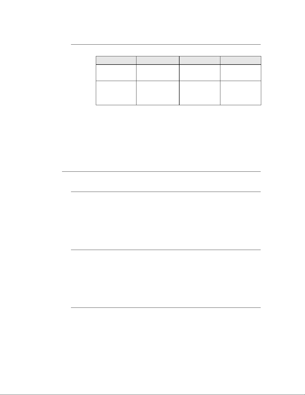
2.2.1. Mechanical
Diameter 1.2 meter 1.5 meter 2.0 meter
Height
(Minimum)
Distributed
Load
Rating*
*Distributed Load Rating is based on an evenly distributed
load to each section. Point loads under 0.37 sq. m
(4 sq. ft) should not exceed 500 kg (1,100 lb.). Nothing over
400 kg (882 lb.) may be applied to a 45-degree segment
outboard of the casters.
16.51 cm
(6.12 in.)
500 kg
(1,100 lb)
Table 2: Mechanical Parameters
16.51 cm
(6.12 in.)
1,000 kg
(2,200 lb)
16.51 cm
(6.12 in.)
1,000 kg
(2,200 lb)
2.3. Turntable Installation Considerations
2.3.1. Conduit
Power and signal line paths must be planned in advance.
Power and signal lines must never run through the same
conduit. Conduit must be in place before pouring concrete
or installing the ground plane. Consider the size of the cable
bundle when selecting conduit diameter.
2.3.2. Electrical Considerations
A qualified and licensed electrical contractor must be used to
install power lines, and the installation should comply with all
applicable regulatory agencies. A dedicated circuit is
required with the shortest distance possible between the
power source and the turntable.
2.3.3. Access
12
An access area underneath the turntable is advisable for
large diameter installations. A service switch is necessary to
deactivate the turntable during service.
©ETS-Lindgren—January, 2006
Rev. B—P#399771
Page 13

Model 2188 Turntable
3. Installation
The turntable installation will vary based on the host location. Several
installation options may be presented in the steps that follow. Please
select the option that applies to your location.
The installation of turntables must be performed by a factory installation
specialist or by individuals who have been authorized by ETS-Lindgren to
do such work. Proper installation of the turntable directly affects
performance. The following installation information is provided to
familiarize the user of the turntable with the installation process.
CAUTION: Ensure power is off and secured before proceeding further.
3.1. Tools Required
• 3/16” Allen wrench
• ¼” Allen wrench
• 3/8” Allen wrenches, qty 3
• 6 mm Allen wrench
• 3/8” ratchet wrench
• 12” crescent wrench
• 15 mm, 12 point socket for
½” square head screws
• 7/16” open/box end wrench
• ½” open/box end wrench
• ¾” open/box end wrench
• 0.120 drill bit for 6-32 self
tapping screws
• #7 Drill bit for ¼-20 tap
3/8” hand drill
•
•
9/32 drill bit
• #2 Phillips screw bit
• #3 Phillips screw bit
• Measuring tape
• Pry bar
• Level
• Square
• Hacksaw
• Black marker
• File
• WD 40
• ¾” pipe clamp ends
• ¾” pipe (length depends on table
size 6 ft. will cover most tables)
• 1 – ½” C-clamps, qty 8
• Cutting Oil
• Syringe for applying conductive
grease
• Grease Gun
• Vacuum
• ½” Hammer Drill
CAUTION: Only qualified personnel must perform lifting of the
turntable assembly using a forklift or other lifting machinery.
Damage to the turntable or serious injury to the personnel may
occur.
©ETS-Lindgren—January, 2006
Rev. B—P#399771
13
Page 14

Model 2188 Turntable
3.2. Unpacking
A qualified installer will perform the following steps in preparation for
installation of the turntable. Please pull the drawings from the back pocket
of this manual to assist in the installation directions that follow.
1. Uncrate all parts. Check all parts for any shipping damage. Ensure
a clear area is available to assemble the turntable unit safely.
NOTE: Do not discard any packing material or parts until the
turntable is fully assembled.
2. Verify that that fiber optic cable is long enough to reach from the
turntable to the control room. When working around the table,
avoid stepping on the fiber optic connectors located on the motor
base.
3. If the turntable is to be installed in a pit, check pit depth and inside
diameter and compare measurements with the drawings for your
turntable size at the back of this manual. The inner diameter of the
receptacle pit should be as follows:
• 1.2 meter turntable = 49.00” (+/-0.25”)
• 1.5 meter turntable = 60.00” (+/-0.25”)
• 2.0 meter turntable = 79.75” (+/-0.25”)
4. Remove the bolts that attach the top onto the turntable drive
assembly. These are the six flathead bolts closest to center of the
tabletop. Remove top and place in position as not to damage any
components on the top. Refer to the assembly drawing 2188-1.2,
2188-1.5 or 2188-2.0 included at the rear of this manual for more
details.
3.3. Positioning the Turntable
5. Using a forklift or other appropriate lifting device, place the turntable
bottom into position. The motorbase with the fiber optic connectors
should point in the direction that the fiber optic cable will be
installed. This position will reduce the chance of the cable being
kinked or twisted.
14
©ETS-Lindgren—January, 2006
Rev. B—P#399771
Page 15

Model 2188 Turntable
Figure 1: Turntable Interior Design
Figure 2: Turntable Pit Locator Detail
©ETS-Lindgren—January, 2006
Rev. B—P#399771
15
Page 16

Model 2188 Turntable
6. Position the table as close as possible to the center. Attach the
measuring bar provided to the brass spacers mounted onto the
bearing. Note the appropriate hole-mount locations in reference to
the size of the turntable to be installed. Rotate the bearing and
ensure approximately
7/8” to 1” spacing exists between the edge of
the outer measuring bar and the diameter of hole cut into the pit.
Adjust if necessary.
7. Once the center is located, using a marker, mark around the
perimeter of the table base or outer floor plates. These marks may
be used for reference if the assembly moves during placement of
the floor shims or anchor plates.
NOTE: When installing the turntable on modular shielding, attempt
to make as many anchor holes miss the floor joint strips as possible
when positioning the table. Use the shim plates provided for this
application.
8. The Model 2188 turntable includes curved floor anchor plates that
are under the base unit. The 1.5m and 2.0m model includes an
outer ring of floor plates to support additional casters. Place
between the base unit and outer plates, the four connector strips
included to ensure proper spacing. Please refer to drawing number
2188-1.2, 2188-1.5 or 2188-2.0 included at the back of this manual
and figure two for the placement and securing of floor plates. If the
turntable is to be installed in a welded chamber with a steel pit and
steel raised floor, please refer to step 12.
3.4. Installing Anchor Plates
9. The anchor plates are held in place by ¼-20 screws and set collars.
Screw the anchor plates to the floor using #14x1” #3 square socket
flat head screws. Drill
up shavings so that you have good contact with the floor. Continue
mounting the rest of the plates.
10. Once all anchor plates are securely mounted, remove the ¼ -20
screws that hold the anchor plates to the base and discard.
11. Proceed to level the table to the raised floor.
1/8” pilot holes for these screws and vacuum
16
©ETS-Lindgren—January, 2006
Rev. B—P#399771
Page 17

Model 2188 Turntable
12. When mounting to a steel pit and steel raised floor, a #7 drill bit for
tapping or a 9/32 drill bit to create “through holes” is required when
mounting anchor plates to the steel raised floor. Locate and mark
holes in each group of anchor plates. Drill and tap or drill through
each hole and then screw in ¼-20 hardware so that the table does
not move as you go around each location. Proceed with leveling
instructions.
CAUTION: Before leveling make sure all ½-13 flange nuts and
clamp collars are backed off all the way to avoid pulling plates off
the floor. Refer to drawings at the back of this manual.
13. Raise the table by turning the ½-13 square head screws clockwise
until the measuring bar top is 3/16” above the raised floor; this is
just a rough finish height. Check height with a leveling instrument
(torpedo laser level or some other device).
Once the table is leveled, tighten flange nuts on the square head
screws and secure set collars on the torque pins down onto the
base top surface and outer plate if applicable. Remove the
measuring bar. Refer to figure three and drawing 2188-1.2 at the
rear of the manual for more details.
3.5. Raised Panel Floor Flange Installation
Figure 3: Turntable Elevation View
The ground ring assembly includes a floor flange with a mounted
brush ring that interfaces with the contact ring mounted underneath
the turntable top. The floor flange provides constant electrical
contact with the ground plane.
©ETS-Lindgren—January, 2006
Rev. B—P#399771
17
Page 18

Model 2188 Turntable
Mounting methods vary according to user specifications.
Clearance holes are provided, at evenly spaced intervals, along the
outside perimeter of the ground ring as a means of attaching the
ring to a customer supplied ground plane. These instructions cover
installation for a paneled floor; please see the section on “Floor
Flange Mounting in Concrete Pit” for further instructions regarding
mounting in a concrete pit.
For this step you will need three ¼” spacers i.e. bolts, drill bits, etc.
A hand drill, 5/32” drill bit, #3 Phillips drive bit, a small square, #14 x
1 wood/metal screws are also required at this time.
The turntables described in this manual each have two floor flange
pieces. All of the flanges are pre-cut at the factory for drop in fit.
Lay the floor flange into the opening of the raised floor and push
outward to the diameter of the opening. Attach the turntable top
onto the brass spacers with the hardware provided.
14. Using a pipe clamp and ¼” Allen wrenches or ¼” pin, place a
spacer between the turntable and flange starting in three places in
the center or on the flange. Once tension exists on all three
wrenches, drill a 5/32” hole through the counter-sunk holes in the
floor flange. Drill completely through the panel and place screws
into the holes. Continue working around the flange completing two
or three holes at a time. Refer to the 2188 1.2 drawing included for
details
NOTE: It is very important that a ¼” gap between turntable top and
ground brush flange mounted on floor flange be held as close as
possible so that the grounding brushes seat properly. Also, it is
important to ensure the flange ends are flush with each other.
15. Continue mounting as stated above until all screws have been
installed. Some screws may fall between the floor panel joints. Try
to position the flanges, ensuring as few screws hit these points as
possible, and making certain that the first or last hole in the flange
is not too close to one of these joints. Also, the top floor joint strips
will need to be trimmed to fit up against the flange.
3.6. Floor Flange Mounting in a Concrete Pit
Mounting to concrete is the same with the exception of the
mounting hardware. Instead of the #14 x 1” square socket flat head
screws, you will use ¼ x 1 3/4” Phillips flat head TAPCON screws.
18
©ETS-Lindgren—January, 2006
Rev. B—P#399771
Page 19

Model 2188 Turntable
Figure 4:Turntable Motorbase
A ½” hammer drill, 3/16 x 3 ½” min. hammer drill bit, and a vacuum
to clean in holes drilled for maximum thread engagement will be
required for this stage of the installation.
NOTE: When drilling holes, watch out for buried conduit and pit
drainpipes. Drill 3/16” holes 2” min. depth.
3.7. Motorbase Attachment
Locate the box that contains the motorbase. The box also includes
the hardware needed to attach the motorbase to the turntable.
Refer to figure four above to locate the drive chain and bolts to
secure the motorbase. Slide the motorbase between the two rails
provided.
Attach three bolts, flat and lock washers provided on each side of
the motorbase, do not tighten them completely at this time.
Attach the chain around the bearing sprocket and the drive
sprocket. Adjust the mortorbase using the two pusher bolts
provided. Allow only ¼ inch maximum side-to-side motion for
proper chain tension on the motor. Finally, tighten the six securing
bolts.
©ETS-Lindgren—January, 2006
Rev. B—P#399771
19
Page 20

Model 2188 Turntable
3.8. Final Leveling of the Table
Once the table is in place with the floor flange and wear strip
mounted, check that the table is level. Ensure that it is level and all
screws, nuts, and collars have been tightened.
3.9. Application of Conductive Grease
Before placing the turntable into operation, apply conductive grease
to the ground brush. Apply the contents of one tube of GC
Electronics conductive grease to the brush. Apply one tube per
meter size of the diameter of the table.
20
©ETS-Lindgren—January, 2006
Rev. B—P#399771
Page 21

Model 2188 Turntable
4. Electrical Installation
CAUTION: Electrical connection should only be performed by a qualified
electrician and subject to local electrical codes.
The Model 2188 is designed to operate using 208-230 VAC single-phase
50 or 60Hz power.
The branch circuit supplying power to the motor base should be protected
from excess current according to local electrical codes. ETS-Lindgren has
provided integral circuit protection in the motor base assembly.
Check that the conductor size is adequate for the motor load and the
distance from the mains source. Improperly sized conductors will lead to
a high voltage drop in the power conductors and cause reduced starting
torque and premature motor failure.
The motor base assembly is provided with an IEC-320 power inlet for
connecting to the mains. Prior to servicing the turntable or the turntable
motor base, remove the power connection for safety.
Connect the fiber-optic control cable and install the power connection per
local electrical code. Please refer to the Model 2090 series positioning
controller manual for instructions on connecting the fiber optic cable. After
the fiber optic cable is installed secure it with a wire tie to one of the
leveling screws.
In order to feed the fiber optic connectors through the waveguide in a
chamber it may be necessary to remove part of the protective sheath.
The removal of a portion of the sheath will allow the connectors to fit
through the hole without bending or kinking the fiber optic cable
excessively. Find the spot in which you will need to remove the sheath
and mark. A very sharp knife is needed to make the splice. Being very
careful, cut around the outside of the sheath at each end of the area
needing to be cut, cut very lightly so as to not cut into the fiber cables.
You should then be able to bend the sheath back and forth until you can
see the fiber cables.
Next, you will need to make a cut down the length of sheath area, being
careful not to cut into fiber cable. You will see two pieces of white string
inside the sheath. Find the string and use it to split the sheath open. Now
insert the cable into the waveguide.
©ETS-Lindgren—January, 2006
Rev. B—P#399771
21
Page 22

Model 2188 Turntable
This page intentionally left blank.
22
©ETS-Lindgren—January, 2006
Rev. B—P#399771
Page 23

Model 2188 Turntable
5. Operation
Please refer to the Model 2090 series positioning controller manual if you
are unfamiliar with the operation of the unit. A manual is included with
each positioning controller shipment and is also available for download
from our website, www.ets-lindgren.com.
With the assembly of the turntable complete the Model 2090 series
controller must be connected to the unit and power applied to both the
motor base and controller in order to continue. Refer to the electrical
installation section if you have questions about how to connect the fiber
optic cables.
Using the Model 2090 series positioning controller check the CW
(clockwise) and CCW (counter clockwise) rotation in both directions by a
few degrees. The position in degrees increases (+) in the CW direction
and decreases (-) in CCW direction.
The turntable is calibrated in the factory to read out 360 degrees
(+ or - 1 degree) for one complete revolution. If the table is not within this
accuracy, the unit can be re-calibrated per the instructions in the
“Turntable Encoder Calibration” section below.
5.1. Editing Positioning Controller Configuration Parameters
To edit a configuration parameter, press the PARAM key to display
the current parameter. Pressing the PARAM key repeatedly will
scroll down through the parameter list, showing each parameter in
turn. While viewing a parameter, the STEP keys (INC/DEC) may
be used to scroll up or down the parameter list. This reduces the
effort necessary to scan through a long parameter list using the
PARAM key. Pressing any of the LIMIT/POSITION selection keys
will return the display to that selection. Pressing any of the
remaining motion keys will return the display to the current position
and execute that motion. Pressing the PARAM key again will
return to the last displayed parameter in the list, allowing easy
transition between parameter adjustment and device operation.
Once the desired limit, position or parameter is visible in the display
window, pressing INCRM, DECRM, or ENTER will toggle into edit
mode. The lowest adjustable digit will flash on and off. Pressing
the LOCAL key for that device will switch the flashing digit to the
next higher digit. In this way, it is possible to rapidly adjust any digit
of a multi-digit parameter or limit.
©ETS-Lindgren—January, 2006
Rev. B—P#399771
23
Page 24

Model 2188 Turntable
5.2. Setting Travel Limits
Figure 5: Turntable Limit Switch
The Model 2188 is fitted with mechanically actuated or “hard” limit
switches. These switches are adjustable to allow for limited travel
beyond zero and 360 degrees. Actuation pins are placed in the
turntable top to engage the limit switch mechanism. The limit
switch mechanism is designed so that the amount of travel is
dictated by the pin position in the turntable top.
The default configuration allows for travel between –45 degrees
and +405 degrees. Remove all pins and the access panel. Move
the turntable so that the access hatch is directly above the limit
switch mechanism (shown in Figure five above). Set the
mechanism to the CCW armed position and insert actuations pins
in the holes on either side of the mechanism 45 degrees away.
Now, set the current position displayed by the controller to 000.0
degrees. Test the lower limit by holding down the DEC key, which
allows the turntable to travel past the soft limit. The turntable
should engage the lower hard limit between -35 and -55 degrees.
You can also test the upper limit by holding down the INC key until
the upper limit is engaged between 395 and 415 degrees.
It is also advised that the user properly set the “soft” limits in the
controller should non-continuous operation be desired.
24
To set the counterclockwise rotational limit for the turntable, press
the DOWN/CCW key under LIMIT. The indicator above this key will
light. Set the limit by pressing the INCRM and DECRM keys under
LIMIT until the desired limit is shown on the display. Then, press
©ETS-Lindgren—January, 2006
Rev. B—P#399771
Page 25

Model 2188 Turntable
the ENTER key. To set the clockwise rotational limit for the
turntable, press the UP/CW key under LIMIT. The indicator light
above this key will light. Set the limit by pressing the INCRM and
DECRM keys under LIMIT until the desired limit is shown on the
display. Press the ENTER key.
WARNING: Ensure the current travel limit settings will not cause
damage to existing cables and equipment located underneath the
turntable.
Should continuous operation be desired, the Model 2090 series
controller permits easy configuration to this type of operation from
the front panel or through the IEEE-488 interface bus. Refer to the
positioning controller manual for more information. The limit pins
should also be removed form the turntable top to allow for
continuous operation.
5.3. Turntable Encoder Calibration
Parameter C, which calibrates the encoder counts to the rotation of
the turntable, must be set to the value 3600. Parameter C Refers to
the encoder calibration parameter. This setting is used to convert
the encoder count values returned from a motor base into the
corresponding centimeter or degree position reading. For
turntables, this represents the number of encoder counts per
revolution. The setting for the Model 2188 turntable series is 3600.
If the given value does not appear to work correctly, the encoder
calibration value can be determined using the following procedure:
1. Set the encoder calibration value to 3600.
2. Ensure that the turntable is positioned to allow more than a full
revolution of travel in the clockwise direction and use the STEP
keys to run the turntable clockwise a few degrees to remove any
play in the table.
3. Mark the current location of the turntable against the ground ring
(masking tape works well for marking), and set the current
position reading to 000.0.
4. Using the STEP keys, rotate the turntable clockwise until it is
again aligned with the mark on the ground ring. For best
results, the last motion should always be in the clockwise
direction to ensure that any play in the gearing between the
motor and encoder is accounted for.
©ETS-Lindgren—January, 2006
Rev. B—P#399771
25
Page 26

Model 2188 Turntable
5. Record the reading of the display, ignoring the decimal point
(i.e. 360.0 would be 3600). This is the encoder calibration
value.
NOTE: If the value is below 3600, the resolution of the encoder
is low and consequently the controller will not provide 0.1degree resolution, even though the display shows that digit. If
the value has gone past 9999, the encoder has too many counts
per meter and the controller cannot correct for it. In this case,
contact ETS-Lindgren for assistance.
6. Enter the encoder calibration value and reset the limits and
position information.
7. Test the turntable by moving it a complete revolution and
comparing the alignment marks. It may be necessary to adjust
the encoder calibration value up or down slightly depending on
the result.
NOTE: When scanning between limits, it is not uncommon to
have a small discrepancy between the absolute position of the
table and the display on the controller. This is because
reversing the direction of rotation reverses any gear play
between the encoder and the table top, allowing that play to be
visible in the positioning accuracy.
5.3.2. Turntable Calibration Example
• The table is set at the “0” degree position. A piece of tape is
placed on the edge of the turntable to line up with the edge
of the gearbox cover. The table is stopped when the tape
travels exactly 360 degrees around. The display on the
controller now reads 356.3 degrees, which is recorded.
• The table is rotated CCW back to zero. The parameter
button is set on the “C” setting. The “C” digits display 3430.
A new “C” setting is now calculated:
• New “C” = (356.3 divided into 360) times 3430 = 3395
(rounded off).
• The decrement the C parameter to 3395 and “ENTER” is
pressed. The “current position” button is pressed to get back
to operation mode.
26
©ETS-Lindgren—January, 2006
Rev. B—P#399771
Page 27

Model 2188 Turntable
• The table is rotated from 0 to 360 and the mark is now within
one degree of being one full turntable revolution. Calibration
is complete.
5.4. Changing Rotation Speed
The Model 2188 turntable is equipped with a variable speed drive.
Firmware Revision 3.11 (or higher) must be installed in the Model
2090 series controller for proper operation of the Model 2188. The
revision level is displayed on the front panel LED display during
startup of the Model 2090 series controller. If the controller does
not have this or a later revision installed, consult the factory for an
upgrade.
To select one of the four speeds, use the POLAR/SPEED button to
toggle through the speed options. It is necessary to set the
controller parameters to configure the controller to properly control
the motor base. Refer to the controller manual to the section that
describes setting the parameters.
Specifically, parameter two must be set to the value three, which is
for variable speed control. Parameter C, which calibrates the
encoder counts to the rotation of the turntable, should be set to the
value 5440. This will insure that the position display will properly
report the full 360 degrees of travel.
5.5. Variable Speed Settings
The Model 2090 series controller parameters S1-S4 control the
variable speed settings for the turntable. These parameters are the
continuous variable speed settings for each of the four speed
selections described below. Each of these parameters can be set
to any value from 1 to 255, with the resulting turntable speed being
roughly an S/255 fraction of the maximum speed. Note that it is the
nature of variable speed drives that there is a minimum speed at
which the motor will operate. For the Model 2188 this minimum
speed setting will be somewhere between 30-75 and should
correspond to a value of 0.5 RPM or less. Below this setting, the
motor will not be able to cause rotation, but will be active until a
Motor Not Moving error (E002) occurs.
©ETS-Lindgren—January, 2006
Rev. B—P#399771
27
Page 28

Model 2188 Turntable
WARNING: Do not operate the turntable in a stalled condition.
Doing so may cause damage to the drive unit and will nullify your
warranty. Always insure that the minimum speed setting specified
in the S1-S4 parameters is above the minimum value at which your
table will turn under normal load.
5.6. Speed Selection
For the Variable Speed Turntable, the Polarization/Flotation button
provides the ability to cycle between the eight preset speeds
described above. For each press of the button, the turntable will
change to the next speed setting. The polarization LEDs will light
to indicate the speed selection in a binary fashion as shown below:
• Speed 1: Both off
• Speed 2: Top on, bottom off
• Speed 3: Top off, bottom on
• Speed 4: Both on
• Speed 5: Both off
• Speed 6: Top on, bottom off
• Speed 7: Top off, bottom on
• Speed 8: Both on
Each speed setting has its own individual overshoot compensation
value to provide proper overshoot correction for each speed
selection.
28
©ETS-Lindgren—January, 2006
Rev. B—P#399771
Page 29

Model 2188 Turntable
5.7. GPIB Commands
The following GPIB commands have been added or modified:
• Sn: Select Speed, where n is 1 or 2 for a two-speed turntable
and 1-4 for a variable speed turntable.
• S?: Query speed selection. Returns 1 or 2 for a two-speed
turntable and 1-4 for a variable speed turntable.
• SSn: Set Speed Value, where “n” is 1-4. This command is valid
only for a variable speed turntable. Valid speed values are from
1 to 255.
Command Usage: SSn <Speed>
Example: Output 708, "SS1 196;"
• Query Speed Value, where “n” is 1-4. This command is valid
only for a variable speed turntable. Returns a speed value from
1 to 255.
Command Usage: SSn?
Example: Output 708, "SS2?;"
5.8. Controller Interface
©ETS-Lindgren—January, 2006
Rev. B—P#399771
29
Page 30

Model 2188 Turntable
This page intentionally left blank.
30
©ETS-Lindgren—January, 2006
Rev. B—P#399771
Page 31

Model 2188 Turntable
6. Infrared Controller
The motor base features an infrared receiver that will respond to a
universal remote control programmed to a specific protocol. Any remote
that continuously transmits and contains the proper TV protocol can be
used.
The basic functions supported are as follows:
Button Command
Power Emergency Stop
Channel Up Up for linear positioner
Channel Down Down for linear positioner
Volume Left Counterclockwise for rotational
positioner
Volume Right Clockwise for rotational
positioner
Mode Polarization for linear positioners
Table 3: Controller Functions
State 1 2 3 4
Power
Init
Up/CW
Down/CCW
Polar
Upper Limit
Lower Limit
Any Any Any Any
Cycling Amber
Green
Green
Green
Red
Red
Table 4: Motorbase Status Indicators
©ETS-Lindgren—January, 2006
Rev. B—P#399771
31
Page 32

Model 2188 Turntable
This page intentionally left blank.
32
©ETS-Lindgren—January, 2006
Rev. B—P#399771
Page 33

Model 2188 Turntable
7. Recommended Maintenance
CAUTION: Do not perform maintenance while turntable is operating.
Disconnect the power connection for safety. Only qualified individuals
should conduct these maintenance inspections.
Regular maintenance will prolong the serviceable life of your turntable.
Follow this recommended schedule. Use the inspection log that follows to
maintain a record of maintenance described below.
7.1. Routine Maintenance
Routine maintenance should be conducted prior to each use of the
turntable.
• Visually inspect the turntable prior to use. Look for foreign
objects in the gap between the turntable top and the floor
flange. If possible, remove the objects to eliminate damage to
the turntable.
• Attempt to rotate the top by hand. Excessive rotation may
indicate a loose drive component.
• Listen for excessive or unusual noise during turntable operation.
7.2. Bi-Annual Maintenance
These maintenance items should occur every six months once the
turntable is put into operation. Prior to conducting any of the
following items, remove the turntable top.
• Grease the casters. Use a good quality bearing grease to
lubricate the casters. Using synthetic grease, grease all
casters. Mobil 1 synthetic and a standard SAE grease gun is
recommended; do not use lithium grease.
• Inspect the ground brush for contaminates. Vacuum the brush
to remove unwanted debris. Add a small amount of conductive
lubricant to the brush interface if required.
• Inspect the ground brush for wear. A well maintained ground
brush should have a long serviceable life.
• Replace the ground brush.
©ETS-Lindgren—January, 2006
Rev. B—P#399771
33
Page 34

Model 2188 Turntable
7.3. Annual Maintenance
These maintenance items should occur every twelve months after
the turntable is put into service.
• Lubricate the main bearing race. Use a grease gun with a good
quality bearing grease. The grease fittings are located inside
the race, 90 degrees apart, underneath the top. Three
discharges from the grease gun in each fitting are adequate.
Using synthetic grease, grease all casters. Mobil 1 synthetic is
recommended; do not use lithium grease.
• Lubricate the chain and sprocket of the chain drive. Apply good
quality grease to the chain and sprocket; do not use lithium
grease.
34
©ETS-Lindgren—January, 2006
Rev. B—P#399771
Page 35

Model 2188 Turntable
EMCO Model 2188 Turntable Maintenance Log
Routine Bi-Annual Annual Routine Bi-Annual Annual Routine Bi-Annual Annual
Routine Check
Remove foreign
objects between
turntable top and
floor flange
Check for
excessive rotation
by hand
Listen for
excessive noise
Bi-Annual Check
Grease the casters
Inspect the ground
brush for
contaminates
Inspect the ground
brush for wear,
replace if
necessary
Annual Check
Lubricate the main
bearing race
Lubricate chain
and sprocket of the
chain drive
Table 6: Turntable Maintenance Log
©ETS-Lindgren—January, 2006
Rev. B—P#399771
35
Page 36

EMCO Model 2188 Turntable
This page intentionally left blank.
36
©ETS-Lindgren—October, 2005
Rev. A—Part#399771
Page 37

8. Warranty
SCOPE AND DURATION OF WARRANTIES
Seller warrants to Buyer that the Standard EMCO Brand Products Excluding 5211 & 5220 be (1) free
from defects in material, manufacturing workmanship, and title, and (2) conform to the Seller’s
applicable product descriptions and specifications, if any, contained in or attached to Seller’s quotation.
If no product descriptions or specifications are contained in or attached to the quotation, Seller ’s
applicable product descriptions and specifications in effect on the date of shipment shall appl y. The
criteria for all testing shall be Seller’s applicable product specifications utilizing factory-specified
calibration and test procedures and instruments.
All product warranties, except the warranty of title, and all remedies for warranty failures are limited in
time as shown in the table below.
Product Warranted Duration of Warranty Period
Standard EMCO Brand Products Excluding
5211 & 5220
Any product or part furnished to Buyer during the warranty period to correct a warranty failure shall be
warranted to the extent of the unexpired term of the warranty applicable to the repaired or replaced
product.
The warranty period shall commence on the date the product is delivered to Buyer; however, if Seller
assembles the product, or provides technical direction of such assembly, the warranty period for such
product shall commence on the date the assembly of the product is complete. Notwithstanding the
foregoing, in the event that the assembly is delayed for a total of thirty (30) days or more from the date
of delivery for any reason or reasons for which Seller is not responsible, the warranty period for such
product may, at Seller’s options, commence on the thirtieth (30th) day from the date such product is
delivered to Buyer. Buyer shall promptly inspect all products upon delivery. No claims for shortages will
be allowed unless shortages are reported to Seller in writing within ten (10) days after delivery. No other
claims against Seller will be allowed unless asserted in writing within thirty (30) days after delivery (or
assembly if the products are to be assembled by Seller) or, in the case of alleged breach of warranty,
within the applicable warranty period.
WARRANTY EXCLUSIONS
Except as set forth in any applicable patent indemnity, the foregoing warranties are exclus ive and in lieu
of all other warranties, whether written, oral, express, implied, or statutory. EXCEPT AS EXPRESSLY
STATED ABOVE, SELLER MAKES NO WARRANTY, EXPRESS OR IMPLIED, BY STATUTE OR
OTHERWISE, WHETHER OF MERCHANTABILITY OR FITNESS FOR ANY PARTICULAR PURPOSE
OR USE OR OTHERWISE ON THE PRODUCTS, OR ON ANY PARTS OR LABOR FURNISHED
DURING THE SALE, DELIVERY OR SERVICING OF THE PRODUCTS. THERE ARE NO
WARRANTIES WHICH EXTEND BEYOND THE DESCRIPTION ON THE FACE HEREOF.
Warranty coverage does not include any defect or performance deficiency (including failure to conform
to product descriptions or specifications) which results, in whole or in part, from (1) negligent storage or
handling of the product by Buyer, its employees, agents, or contractors, (2) failure of Buyer to prepare
the site or provide an operating environmental condition in compliance with any applicable instructions
or recommendations of Seller, (3) absence of any product, component, or accessory recommended by
Seller but omitted at Buyer’s direction, (4) any design, specification, or instruction furnished by Buyer, its
employees, agents or contractors, (5) any alteration of the product by persons other than Seller, (6)
combining Seller’s product with any product furnished by others, (7) combining incompatible products of
Seller, (8) interference with the radio frequency fields due to conditions or causes o utsid e the product as
furnished by Seller, (9) improper or extraordinary use of the product, or failure to comply with any
applicable instructions or recommendations of Seller, or (10) acts of God, acts of civil or military
authority, fires, floods, strikes or other labor disturbances, war, riot, or any other causes beyond the
reasonable control of Seller. This warranty does not cover (1) contact fingers or replacements unless
loss is caused by a defect in material or manufacturing workmanship within the scope of this warranty
(2) items designed to be consumable and (3) removal and reconstruction of walls, partitions, ceilings
and other facility costs arising from repair or replacement of the product or parts thereof by Seller under
the warranty. Seller does not warranty products of others which are not included in Seller’s published
price lists for shielding products and systems supplies and accessories.
2 Years
©ETS-Lindgren—January, 2006
Rev. B—P#399771
37
Page 38

Model 2188 Turntable
BUYER’S REMEDIES
If Seller determines that any product fails to meet any warranty during the applicable warranty period,
Seller shall correct any such failure by either, at its option, repairing, adjusting, or replacing without
charge to Buyer any defective or nonconforming product, or part or parts of the product. Seller shall
have the option to furnish either new or exchange replacement parts or assemblies.
Warranty service during the applicable warranty period will be performed wit ho ut charge to Buyer within
the contiguous 48 United States during Seller’s normal business hours. After the warranty period,
service will be performed at Seller’s prevailing service rates. Subject to the availability of personnel,
after-hours service is available upon request at an additional charge. For service outside the contiguous
48 United States, travel and per diem expenses, when required, shall be the responsibility of the Buyer,
or End User, whichever is applicable.
The remedies set forth herein are conditioned upon Buyer promptly notifying Seller within the applicable
warranty period of any defect or nonconformance and making the product availab le for correction.
The preceding paragraphs set forth Buyer’s exclusive remedies and Seller’s sole liability for claims
based on failure of the products to meet any warranty, whether the claim is in contract, warranty, tort
(including negligence and strict liability) or otherwise, and however i nstituted, and, upon the expiration
of the applicable warranty period, all such liability shall terminate. IN NO EVENT SHALL SELLER BE
LIABLE TO BUYER FOR ANY SPECIAL INDIRECT, INCIDENTAL OR CONSEQUENTIAL DAMAGES
OF ANY KIND ARISING OUT OF, OR AS A RESULT OF, THE SALE, DELIVERY, NON-DELIVERY,
SERVICING, ASSEMBLING, USE OR LOSS OF USE OF THE PRODUCTS OR ANY PART
THEREOF, OR FOR ANY CHARGES OR EXPENSES OF ANY NATURE INCURRED WITHOUT
SELLER’S WRITTEN CONSENT DESPITE ANY NEGLIGENCE ON BEHALF OF THE SELLER. IN NO
EVENT SHALL SELLER’S LIABILITIES UNDER ANY CLAIM MADE BY BUYER EXCEED THE
PURCHASE PRICE OF THE PRODUCT IN RESPECT OF WHICH DAMAGES ARE CLAIMED. This
agreement shall be construed in accordance with laws of the State of Illinois. In the event that any
provision hereof shall violate any applicable statute, ordinance, or rule of law, such provision shall be
ineffective to the extent of such violation without invalidating any other provision hereof.
Any controversy or claim arising out of or relating to the sale, delivery, nondelivery, servicing,
assembling, use or loss of use of the products or any part thereof or for any charges or expenses in
connection therewith shall be settled in Austin, Texas by arbitration in accordance with the Rules of the
American Arbitration Association, and judgment upon the award rendered by the Arbitrator ma y be
entered in either the Federal District Court for the Western District of Texas or the State District Court in
Austin, Texas, all of the parties hereto consenting to personal jurisdiction of the venue of such court and
hereby waive the right to demand a jury trial under any of these actions.
38
©ETS-Lindgren—January, 2006
Rev. B—P#399771
Page 39

9. Addendum A: Drawings
Please locate the drawings placed in pocket of the back cover of this
manual. Drawings include ETS-Lindgren drawing numbers:
• 2188-1.23B
• 2188-1.53 rev. 2
• 2188-2.03 rev. 1
• 108912C
• 110053B
• 110277 rev. 2
• 110406 rev. 2
• 398790
©ETS-Lindgren—January, 2006
Rev. B—P#399771
39
 Loading...