

Page 1
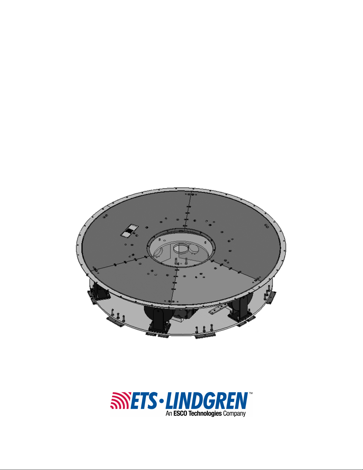
Model 2181
Electric-Powered Turntable
2-Meter, 3-Meter,
4-Meter, 5-Meter
User Manual
Model 2181 2.0-meter turntable
Page 2
ETS-Lindgren L.P. reserves the right to make changes to any products herein to improve
functioning or design. Although the information in this document has been carefully reviewed and
is believed to be reliable, ETS-Lindgren does not assume any liability arising out of the
application or use of any product or circuit described herein; nor does it convey any license under
its patent rights nor the rights of others. All trademarks are the property of their respective
owners.
©Copyright 2007–2008 by ETS-Lindgren L.P. All Rights Reserved. No part of this
document may be copied by any means without written permission from
ETS-Lindgren L.P.
Trademarks used in this document: The ETS-Lindgren logo is a trademark of ETS-Lindgren L.P.
Revision Record
MANUAL,2181 Turntable Series | Part #399289, Rev. D
Revision Description Date
A Initial Release February, 2007
B Added 2-meter turntable; updated 3-meter
turntable specifications
C Updated 3-meter turntable drawing; added
4-meter turntable drawings/updated
specifications
D Added 5-meter turntable information and
drawings; rebranding
September, 2007
November, 2007
June, 2008
ii |
Page 3

Table of Contents
Notes, Cautions, and Warnings.........................................................................v
1.0 Introduction...................................................................................................7
Model 2181 Standard Configuration................................................................................... 7
Turntable Assembly...............................................................................................7
Shield Room Feed-through ................................................................................... 8
Model 2090 Series Multi-Device Positioning Controller..................................................... 8
Model 2181 Optional Items................................................................................................. 8
Infrared Remote Controller.................................................................................... 8
Slip Ring ................................................................................................................ 9
EUT Power Outlets................................................................................................9
Mounted Line Impedance Stabilization Network................................................... 9
Additional Fiber Optic Cables..............................................................................10
ETS-Lindgren Product Information Bulletin...................................................................... 10
2.0 Maintenance................................................................................................11
Recommended Maintenance Schedule ........................................................................... 11
6-Month Service .................................................................................................. 11
12-Month Service ................................................................................................ 12
Replacement and Optional Parts...................................................................................... 12
Service Procedures.......................................................................................................... 12
3.0 Specifications..............................................................................................13
Electrical Specifications.................................................................................................... 13
Mechanical Specifications................................................................................................ 13
4.0 Turntable Installation Considerations.......................................................15
Before You Begin—Precautions....................................................................................... 15
Power and Signal Lines....................................................................................................16
Conduit ................................................................................................................ 16
Electrical Considerations..................................................................................... 16
Access................................................................................................................. 16
Outdoor Installations......................................................................................................... 16
Drainage.............................................................................................................. 16
Cold Climate Conditioning................................................................................... 16
| iii
Page 4

5.0 Electrical Installation..................................................................................17
Model 2181 Electrical Installation.....................................................................................17
Connecting the Model 2090 Controller.............................................................................18
6.0 Assembly and Installation..........................................................................19
Assembly Instructions....................................................................................................... 19
Floor Flange Installation in a Paneled Floor..................................................................... 20
Floor Flange Installation in a Concrete Pit ....................................................................... 23
IR Repeater Installation.................................................................................................... 23
Installation Assembly Components..................................................................... 23
Required Tools for Installation............................................................................. 23
Installation Steps................................................................................................. 24
7.0 Operation.....................................................................................................25
Editing Positioning Controller Configuration Parameters................................................. 25
Setting Travel Limits......................................................................................................... 26
Turntable Encoder Calibration.......................................................................................... 28
Turntable Calibration Example............................................................................ 29
Changing Rotation Speed ................................................................................................ 29
Variable Speed Settings................................................................................................... 29
Speed Selection ............................................................................................................... 30
GPIB Commands.............................................................................................................. 30
Appendix A: Warranty......................................................................................33
Appendix B: EC Declaration of Conformity....................................................35
iv |
Page 5
Notes, Cautions, and Warnings
Note: Denotes helpful information intended to provide tips for
See the ETS-Lindgren Product Information Bulletin for safety, regulatory, and
other product marking information.
better use of the product.
Caution: Denotes a hazard. Failure to follow instructions
could result in minor personal injury and/or property
damage. Included text gives proper procedures.
Warning: Denotes a hazard. Failure to follow instructions
could result in SEVERE personal injury and/or property
damage. Included text gives proper procedures.
| v
Page 6

This page intentionally left blank.
vi |
Page 7

1.0 Introduction
The ETS-Lindgren Model 2181 Turntable is an electric-powered turntable
platform system designed for use with the Model 2090 Series Multi-Device
Positioning Controller for EMI compliance testing. The Model 2181 is designed
for indoor or outdoor use, and is available in 2-meter, 3-meter, 4-meter, and
5-meter sizes.
The top of the turntable is conductive with a continuous ground brush to
electrically couple it to the ground plane. The ground brushes are attached
directly to the chamber floor by the floor flange, and are in continuous contact
with the turntable top. The brushes point downward from the floor flange.
All models utilize a pinion and gear drive with a gear reducer and electric motor
located beneath the platform. The bearing on which the turntable rotates has the
drive teeth cut directly on the outside and will easily support most Equipment
Under Test (EUT). Support for the turntable includes casters that aid in the
support of cantilevered loads on the outside of the turntable.
The turntable top is sectional to provide easy access if service is required. On
standard models, a 15-cm hole is provided in the center of the turntable to
accommodate customer supplied cabling to and from the EUT.
To prevent over-travel of the turntable in either direction of movement, hard limits
are provided in the form of pins that actuate switches located below the tabletop.
These pins allow limits to be set and allow as much as two full rotations. Rotation
speed can be varied from the front panel of the Model 2090 controller or through
the IEEE-488 interface bus.
Model 2181 Standard Configuration
TURNTABLE ASSEMBLY
Featuring continuous or non-continuous operation, the turntable assembly
includes:
• 3-phase electric motor unit
• Heavy-duty variable speed drive system
• Conductive sectional top for easy service access
• Convenient rotational limit adjust switches
Introduction | 7
Page 8

• Limit override feature
• Ground ring assembly with ground brush and floor flange
• 10-meter fiber optic control cables
Additionally, the turntable is infrared compatible, and can be used with an
optional ETS-Lindgren Infrared Remote Controller (IR remote). For more
information on using an IR remote, see Infrared Remote Controller on page 8.
SHIELD ROOM FEED-THROUGH
The feed-through routes the fiber optic control cable from the control room to the
shield room, maintaining satisfactory shielding attenuation. The unit is made of
brass for conductivity and provides attenuation of greater than 100 dB at 10 GHz.
A single 22.25-mm (.875-in) hole is required for mounting.
Model 2090 Series Multi-Device Positioning Controller
The Model 2090 controller is a separate component required for Model 218 1
Model 2181 Optional Items
operation.
The Model 2090 Series Multi-Device Positioning Controller provides control for
two separate devices, such as ETS-Lindgren towers and turntables, plus the
control of four auxiliary devices. The Model 2090 controller includes a GPIB bus
and is compatible with most popular software, and electronically controls speed
adjustment through the GPIB interface or front panel.
INFRARED REMOTE CONTROLLER
The Model 2181 is infrared compatible, and can be used with a universal remote
control programmed to a specific protocol, such as the ETS-Lindgren Infrared
Remote Controller (IR remote).
8 | Introduction
Page 9
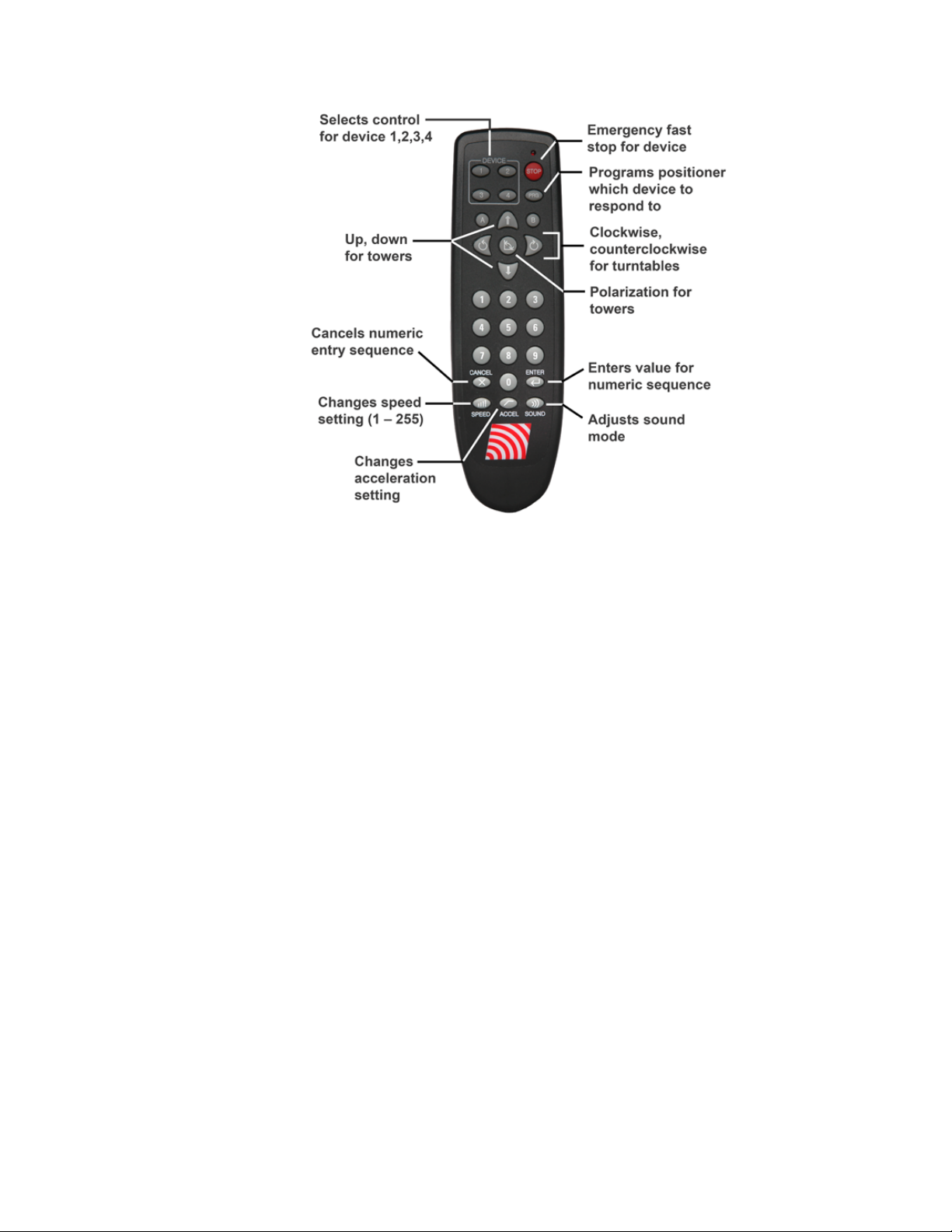
The IR remote communicates with an infrared receiver in the Model 2181
motor base through an IR repeater installed in the floor near the turntable. See
IR Repeater Installation on page 23 for instructions on installing an IR repeater.
SLIP RING
Allows continuous rotation of the turntable through the latest technology in
mercury slip rings, and either Schuko or NEMA connectors can be ordered with
the slip ring. The current rating for the standard electrical assembly is
20 amperes. Contact ETS-Lindgren for custom requirements on slip rings.
EUT POWER OUTLETS
Receptacles are usually mounted on the base of the turntable at the center axis
point. These receptacles can be custom mounted, flush with the tabletop on
some turntables. Contact ETS-Lindgren for information.
MOUNTED LINE IMPEDANCE STABILIZATION NETWORK
A Line Impedance Stabilization Network (LISN) can be mounted to the underside
of some turntables. This option is only practical on larger turntables with sufficient
clearance.
Introduction | 9
Page 10

ADDITIONAL FIBER OPTIC CABLES
Additional lengths of fiber optic cable may be ordered.
ETS-Lindgren Product Information Bulletin
See the ETS-Lindgren Product Information Bulletin included with your shipment
for the following:
• Warranty information
• Safety, regulatory, and other product marking information
• Steps to receive your shipment
• Steps to return a component for service
• ETS Lindgren calibration service
• ETS Lindgren contact information
10 | Introduction
Page 11
2.0 Maintenance
WARRANT Y
Before performing any maintenance, follow the safety
information in the ETS-Lindgren Product Information Bulletin
included with your shipment.
Regularly inspect all equipment and conduct scheduled
maintenance in accordance with the factory recommendations
provided.
BEFORE SERVICING: CONTACT ETS-LINDGREN
(+1.512.531.6400)—Servicing or modifying the unit without
ETS-Lindgren authorization may void your warranty. If an attempt
to service the unit must be made, disconnect all electrical power
prior to beginning. Voltages exist at many points within the
instrument that could, if contacted, cause personal injury. Only
trained service personnel should perform adjustments and/or
service procedures upon this instrument. Capacitors inside this
instrument may still be charged even when the instrument is
disconnected from the power source.
Recommended Maintenance Schedule
Regular maintenance will prolong the effective operation and reliability of your
turntable. Follow the recommended schedule for 6-month and 12-month service.
Do not perform maintenance while the turntable is operating.
6-MONTH SERVICE
Check the gearbox for fluid leakage. A collection of slight film is normal, but
puddles of fluid are not normal. The gearbox is lubricated and sealed at the
factory. Under normal conditions, the gearbox should not require servicing during
its life.
Maintenance | 11
Page 12
12-MONTH SERVICE
• Lubricate the main bearing race with a grease gun containing good quality
bearing grease. The grease fittings are located inside the race, 90 degrees
apart, beneath the top. Three discharges from the grease gun in each fitting
are adequate.
• Lubricate the gear teeth with good quality grease.
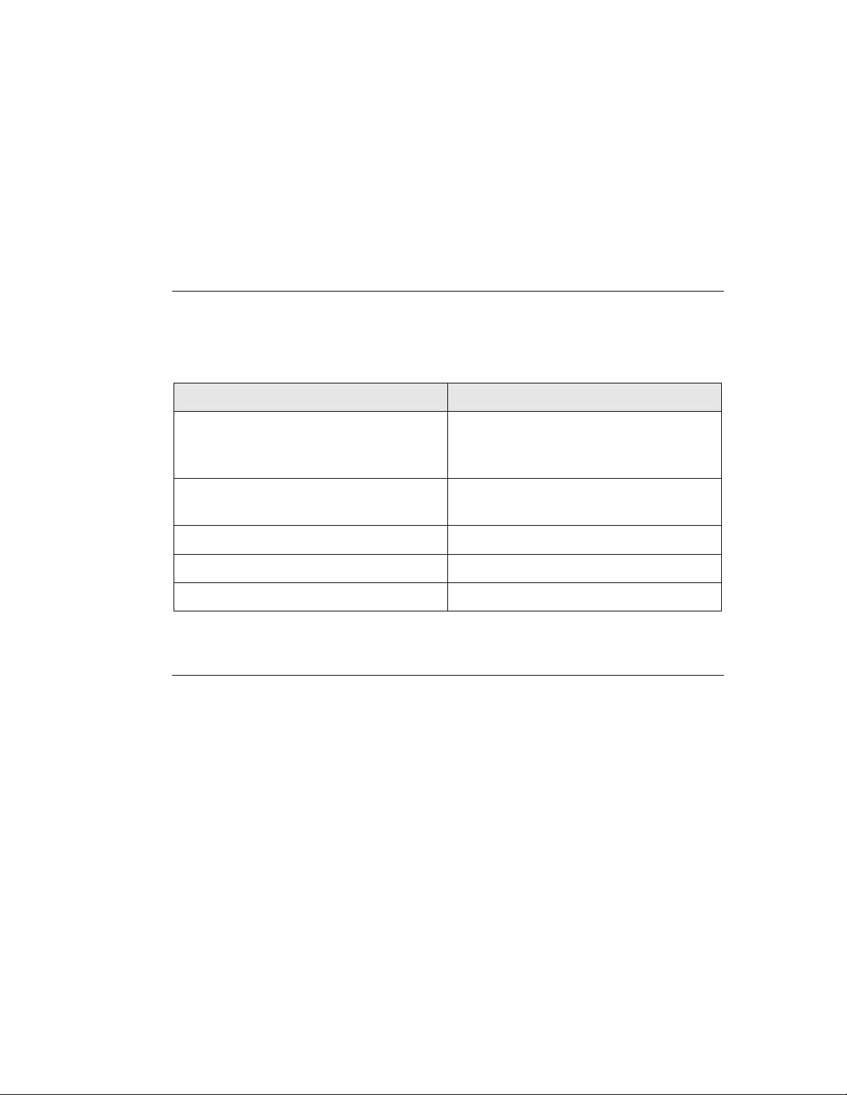
Replacement and Optional Parts
Following are the part numbers for ordering replacement or optional parts for the
Model 2181 Turntable. For additional information on available replacement and
optional parts, see Model 2181 Standard Configuration on page 7.
Part Description Part Number
Turntable assembly For a list of all turntable parts, see the
drawings located in the back pocket of
this manual.
Model 2090 Series Multi-Device
Positioning Controller
IR Remote Controller 707030
NEMA connectors for slip ring 103441
Schuko connectors for slip ring 103351
Service Procedures
For the steps to return a system or system component to ETS-Lindgren for
service, see the Product Information Bulletin included with your shipment.
2090
12 | Maintenance
Page 13
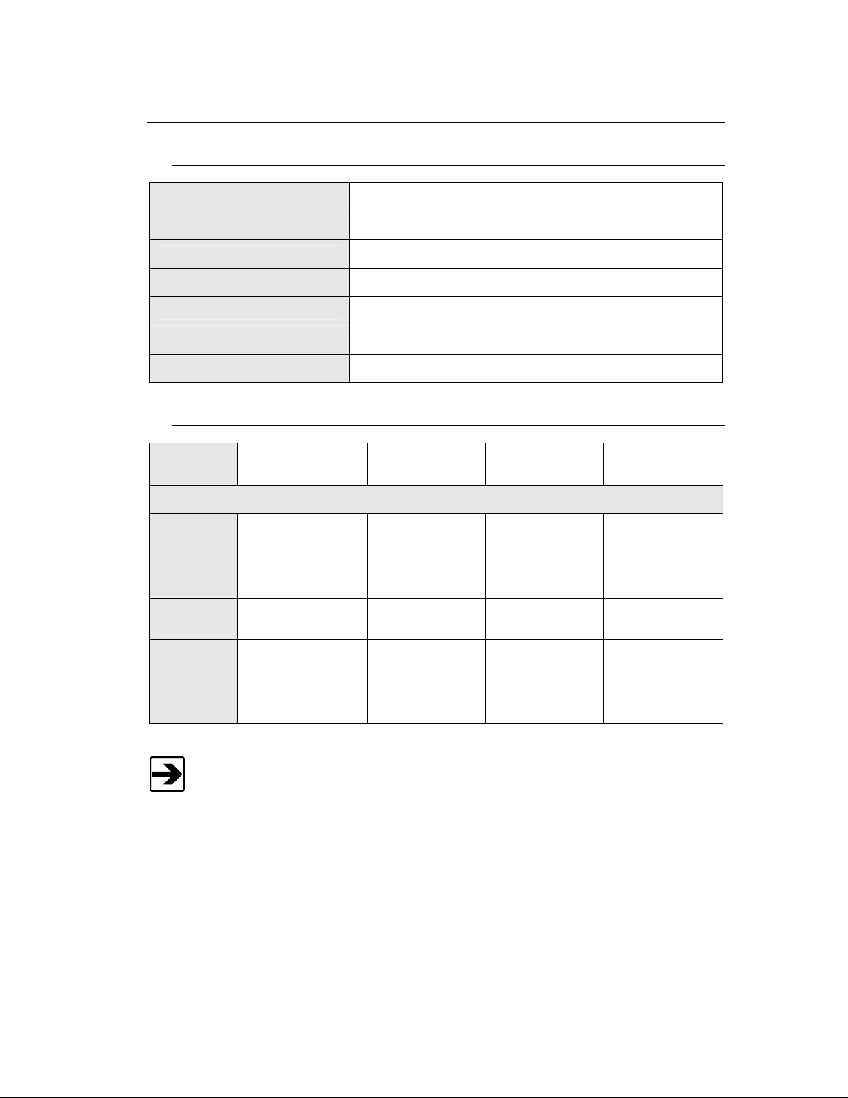
3.0 Specifications
Electrical Specifications
Drive Speeds:
Nominal AC Voltage:
Input Frequency:
Current Rating:
Current Draw:
RPM:
Phase:
Mechanical Specifications
Diameter:
Nominal Height
Minimum:
Maximum:
2.0 m
6.56 ft
44.78 cm
17.63 in
46.99 cm
18.50 in
Variable
200–230 VAC
50/60 Hz
15 amp service
< 10 amps
0.5 – 2.0
Single (1)
3.0 m
9.84 ft
44.78 cm
17.63 in
46.99 cm
18.50 in
4.0 m
13.12 ft
44.78 cm
17.63 in
46.99 cm
18.50 in
5.0 m
16.40 ft
44.78 cm
17.63 in
46.99 cm
18.50 in
Required Pit
Diameter:
Top
Construction:
Distributed
Load Rating:
202.56 cm ± 0.64 cm
79.75 in ± 0.25 in
Sectional
aluminum
1500 kg
3300 lb
302.6 cm ± 0.64 cm
119.12 in ± 0.25 in
Sectional
aluminum
4000 kg
8800 lb
402.6 cm ± 0.64 cm
158.5 in ± 0.25 in
Sectional
aluminum
6000 kg
13200 lb
504.83 cm ± 0.64 cm
198.75 in ± 0.25 in
Sectional
aluminum
6800 kg
15000 lb
Distributed Load Rating applies when:
• Load is evenly distributed on top;
• No point loads under 0.19 sq m (2.0 sq ft) should exceed 100 kg
(220 lb);
• And not over 28.5 kg (62.8 lb) should be applied to a 45-degree
segment at the table outer edge.
Specifications | 13
Page 14

This page intentionally left blank.
14 | Specifications
Page 15

4.0 Turntable Installation Considerations
Before assembling, installing, or connecting any components,
follow the safety information in the ETS-Lindgren
Product Information Bulletin included with your shipment.
Pre-planning is essential for a successful installation. Discuss your requirements
will your sales representative and request dimensional drawings prior to site
construction.
Before You Begin—Precautions
Read this manual completely before starting installation. This
equipment should be installed and operated only by qualified
personnel.
Do not attempt to service unless qualified to do so. As with any
electrical equipment, make sure unit electrical power has been
disconnected and secured when performing scheduled
maintenance or adjustments.
WARRAN TY
Do not make any modifications to this unit without consulting
the factory directly.
Regularly inspect all equipment and conduct scheduled
maintenance in accordance with the factory recommendations
provided.
Only use replacement parts and fasteners ordered directly from
the factory.
Stay clear of all moving components on this equipment.
Do not operate turntable while someone is physically on the
turntable top.
Turntable Installation Considerations | 15
Page 16

Do not, at any time, place hands or feet in the vicinity of the
drive pinion on the turntable.
Power and Signal Lines
CONDUIT
Power and signal line paths should be planned in advance. Con duit should be in
place before pouring concrete or installing the ground plane. Consider the size of
the cable bundle when selecting conduit diameter.
ELECTRICAL CONSIDERATIONS
A qualified and licensed electrical contractor should install power lines, and the
installation should comply with all applicable regulatory agencies. A dedicated
circuit should be used, with the shortest distance possible between the power
source and the turntable.
ACCESS
An access area beneath the turntable is advisable for large diameter
installations. A service switch should be installed to deactivate the turntable
during service.
Outdoor Installations
DRAINAGE
A centerline drain of at least 15 cm (6 in) must be installed to provide proper
drainage during rainstorms and other moisture-collecting situations.
COLD CLIMATE CONDITIONING
The oil used in the gear assemblies will congeal at 2 degrees C (28 degrees F).
Turntables operated in these temperatures should include a heat source or
dehumidifier, or both.
16 | Turntable Installation Considerations
Page 17

5.0 Electrical Installation
Model 2181 Electrical Installation
The Model 2181 Turntable is configured to operate using 200-230 VAC, single
phase, 50/60 Hz service. It is recommended to operate at this voltage level to
reduce the surge currents necessary to power an electric motor.
1. The branch circuit supplying power to the motor base should be
protected from excess current according to local electrical codes. An
integral circuit breaker is mounted inside the main bearing on one of the
bearing support blocks. The circuit breaker is specifically designed for
the inductive load presented by the electric motor.
Before assembling, installing, or connecting any components,
follow the safety information in the ETS-Lindgren
Product Information Bulletin included with your shipment.
Electrical installation must be performed by a qualified
electrician, and in accordance with local and national electrical
standards.
2. Make sure the conductor size is adequate for the motor load and the
distance from the mains source. Improperly sized conductors will lead to
a high voltage drop in the power conductors and cause reduced starting
torque and premature motor failure.
3. The motor base assembly is provided with a non-terminated flexible
conduit with input power leads exposed. The flexible conduit is to be
terminated into a junction box fitted on or near the motor base. Terminate
the power leads of the motor base assembly according to local electrical
code requirements. Following is the conductor color code:
Brown: AC high
Blue: AC neutral
Green/Yellow: Protective earth/safety ground
Connect the fiber optic control cable and install the power connection according
to local electrical code. See the Model 2090 Series Multi-Device Controller
Manual for information on connecting the fiber optic cable. After the fiber optic
cable is installed, secure it with a wire tie to one of the leveling screws.
Electrical Installation | 17
Page 18

To feed the fiber optic connectors through the waveguide in a chamber, it may be
necessary to remove part of the protective sheath. This removal allows the
connectors to fit through the hole without excessively bending the fiber optic
cable. Find and mark the spot where you will need to remove the sheath. Use a
sharp knife to carefully cut around the outside of the sheath at each end of the
defined area. Cut very lightly to avoid cutting into the fiber optic cables, and then
bend the sheath back and forth to expose the fiber optic cables.
Next, make a cut down the length of sheath area, being careful not to cut into
fiber optic cable. Inside the sheath are two pieces of white string. Find the string
and use it to split the sheath open. Insert the fiber optic cable into the waveguide.
Connecting the Model 2090 Controller
Any combination of primary devices (towers, turntables, reverberation paddles,
MAPS, and so on) can be connected to the two device interface ports located on
the rear panel of the Model 2090 Series Multi-Device Positioning Controller. For
easy set up of an EMC facility, it is recommended that the turntable be connected
to the Device 2 port. The default settings for the controller are for a tower
connected to the Device 1 port and a turntable connected to the Device 2 port.
Primary device connection is accomplished with a dual fiber optic cable included
with the device. This cable terminates into two ST connectors that are identical at
both ends. The cable is symmetrical, so either end can be connected to the
controller. A fiber optic cable connected to the IN port of a device should be
connected to the primary OUT port of the motor base at the other end. Similarly,
a fiber optic cable connected to the OUT port of the device should be connected
to the primary IN port of the motor base at the other end. Older motor base
designs have only one fiber optic connector pair, but the newer motor base
interface provides a secondary interface reserved for future expansion.
Fiber optic cabling for each device should not hang unsupported from the rear
panel of the controller. The fibers and connectors are easily broken if twisted or
bent. Keep the fiber optic cables as straight as possible from the connector to
the protective sheath.
Using the Model 2090 controller or optional Infrared Remote Controller
(IR remote), rotate the motor base shaft to verify proper operation. Run the
motor base down to the lower limit counterclockwise, and then back it off from
the lower limit a small amount. The previous step will help when it is time to set
the rotation limits for the turntable.
The soft rotational limits in the Model 2090 controller must be
set. Make sure the travel limit settings will not cause damage to
user installed cables and equipment mounted on the table.
18 | Electrical Installation
Page 19

6.0 Assembly and Installation
Before assembling, installing, or connecting any components,
follow the safety information in the ETS-Lindgren
Product Information Bulletin included with your shipment.
Prior to assembly and installation, see the drawings located in the back pocket
of this manual.
Proper installation of the turntable directly affects performance. The installation of
turntables two meters and larger will be performed by factory installation
specialists or individuals authorized by ETS-Lindgren to perform such work. The
following installation information is included only to provide an informational
overview of the installation process.
Do not discard any packing material until the turntable is fully installed and
operational.
Assembly Instructions
1. Uncrate all parts and check for shipping damage. Create a clear area to
safely assemble the turntable unit. Do not discard any packing material
until unit is fully assembled.
2. Remove the bolts that attach the top onto the turntable drive assembly.
Make note of the placement of each top section as it is removed. See the
assembly drawings in the back of this manual.
Only qualified personnel should use a forklift or other lifting
machinery.
3. Using a forklift or other appropriate lifting machinery, place the turntable
bottom or bearing support section into position. If the turntable is to be
installed in a pit, center and level the assembly.
Make sure power is off and secured before proceeding.
Assembly and Installation | 19
Page 20

4. The drawings in the back pocket of this manual show the placement of
floor plates and leveling screws to anchor and level the turntable. Anchor
the turntable through the attachment holes using the concrete expansion
bolts provided. After installing the floor plates and leveling screws, level
the entire turntable by adjusting all the leveling screws between and
under the casters, and in the center section of the turntable.
5. Tighten all lock nuts accompanying the leveling screws to lock the height
of the turntable into place.
6. Connect the fiber optic control cable and install the power connection
according to local electrical code. The standard power configuration is
230 VAC 50/60 Hz.
Electrical connection is subject to local electrical codes, and
should only be performed by a qualified electrician.
Keep all body parts away from the drive pinion when the
turntable is energized.
7. Follow the instructions in the next section, Floor Flange Installation in a
Paneled Floor, to install the ground ring assembly.
8. Reinstall the top section removed in step 3 of these instructions.
Floor Flange Installation in a Paneled Floor
A 2-meter Model 2181 Turntable is depicted in the following illustrations.
20 | Assembly and Installation
Page 21

When the turntable is positioned as close as possible to the center, attach the
measuring bar to the brass spacers mounted onto the bearing. Appropriate
hole-mount locations correspond to the size of the turntable. Rotate the bearing
and make sure approximately
7/8-in to 1-in spacing exists between the edge of
the outer measuring bar and the diameter of hole cut into the pit. Adjust as
required.
The ground ring assembly includes a floor flange with a mounted brush ring that
interfaces with the contact ring mounted beneath the turntable top. The floor
flange provides constant electrical contact with the ground plane.
Mounting methods vary according to user specifications. Clearance holes are
provided at evenly spaced intervals along the outside perimeter of the floor
flange to attach to a customer supplied ground plane. These instructions
describe installation for a paneled floor. For concrete pit mounting instructions
see Floor Flange Installation in Concrete Pit on page 23.
Installing the ground ring assembly requires these tools:
• 1/4-in spacers (3)
• Hand drill
• 5/32-in drill bit
• #3 Phillips drive bit
• Small square
• #14 x 1 wood/metal screws
Assembly and Installation | 21
Page 22

The turntables have a quantity of floor flange pieces depending on the size of the
turntable. All flanges are pre-cut at the factory for a drop-in fit.
A 2-meter Model 2181 is depicted in the following. The turntable top is shown
as a partial cut-away to provide a view of internal components.
1. Lay the floor flange into the opening of the raised floor and push outward
to the diameter of the opening.
2. Attach the turntable top onto the center bearing with the hardware
provided.
3. Using a pipe clamp and 1/4-in Allen wrenches or 1/4-in pin, place a
spacer between the turntable and floor flange starting in three places in
the center or on the flange.
4. Once tension is placed on all three wrenches, drill a 5/32-in hole through
the counter-sunk holes in the floor flange. Drill completely through the
panel and place screws into the holes.
5. Continue working around the floor flange, completing two or three holes
at a time.
Make sure that a 1/4-in gap between the turntable top and the mounted brush
ring be held as close as possible so that the grounding brushes seat properly.
Also, make sure the flange ends are flush with each other.
22 | Assembly and Installation
Page 23

6. Continue mounting until all screws are installed. Some screws may fall
between the floor panel joints. Try to position the flanges, making sure as
few screws hit these points as possible, and making sure that the first or
last hole in the flange is not too close to one of these joints. Trim the top
floor joint strips to fit up against the flange.
Floor Flange Installation in a Concrete Pit
Installing in a concrete pit is the same as a paneled floor, with the exception of
the mounting hardware. Instead of the #14 x 1-in square socket flat head screws,
use 1/4 x 1-3/4-in Phillips flat head concrete anchors.
These tools are required for the next stage of installation:
• 1/2-in hammer drill
• 3/16 x 3 1/2-in hammer drill bit, at minimum
• Vacuum to clean inside the drilled holes for maximum thread
engagement
When drilling holes, be aware of buried conduit and pit drainpipes. Drill 3/16-in
IR Repeater Installation
holes, two inches minimum depth.
INSTALLATION ASSEMBLY COMPONENTS
• Infrared sensor
• Mounting collar
• IR-100 control unit
• IR flasher LED
• 9-12VDC power supply
• Connection cable
• Flathead mounting screws
REQUIRED TOOLS FOR INSTALLATION
• Electric drill
• 1-in hole saw to create a
• 1/16-in drill bit
Assembly and Installation | 23
Page 24

• Small flat blade screwdriver
• Phillips #2 bit driver
• Adhesive tape
INSTALLATION STEPS
1. Choose a location for the IR infrared sensor that is away from traffic.
2. Using a 1-in hole saw, cut an opening in the floor for the IR sensor.
3. Connect the V+, GND, and SIG wires to the IR sensor as shown in the
diagram, and feed the cable through the hole.
4. Use the 1/16-in drill bit and four flathead mounting screws to mount the
IR sensor collar.
5. Connect the V+, GND, and SIG wires from the IR sensor to the
IR-100 control unit as shown in the diagram.
6. Using adhesive tape, attach the IR flasher LED directly over the IR input
on the motor control box.
7. Connect the IR flasher to port 1 on the IR-100 control unit.
8. Plug the 9-12VDC power supply into the power connector on the
IR-100 control unit, and then plug the power supply into a 120 VAC
outlet.
24 | Assembly and Installation
Page 25

7.0 Operation
Before placing into operation, follow the safety information in the
ETS-Lindgren Product Information Bulletin included with your
shipment.
If you are unfamiliar with the operation of the controller, see the
Model 2090 Series Multi-Device Controller Manual. A manual is included with
each positioning controller shipment and is also available for downl oad from
www.ets-lindgren.com
With the assembly of the turntable complete, the Model 2090 Series Multi-Device
Positioning Controller must be connected to the unit and power applied to both
the motor base and controller in order to continue. See the Model 2090 controller
manual for information on connecting the fiber optic cable.
Use the Model 2090 controller to check the clockwise (CW) and
counterclockwise (CCW) rotation in both directions by a few degrees. The
position in degrees increases (+) in the CW direction and decreases (-) in CCW
direction.
.
The turntable is calibrated in the factory to read out 360 degrees (plus or minus
1 degree) for one complete revolution. If the turntable is not within this range, the
unit can be re-calibrated using the instructions in Turntable Encoder Calibration
on page 28.
Editing Positioning Controller Configuration Parameters
Key Function
PARAM
To edit a configuration parameter:
• Press PARAM key to display the current parameter.
• Press PARAM key repeatedly to scroll through the
parameter list, displaying each parameter.
STEP (INC/DEC) To scroll up or down the parameter list while viewing a parameter.
Reduces the effort necessary to scan through a long parameter list
using the PARAM key.
LIMIT/POSITION Press any of the LIMIT/POSITION selection keys to return the display
to that selection.
Press any of the remaining motion keys to return the display to the
current position and execute that motion.
Press the PARAM key again to return to the last displayed parameter
in the list, allowing easy transition between parameter adjustment and
device operation.
Operation | 25
Page 26

Key Function
INCRM, DECRM,
or ENTER
Once the desired limit, position, or parameter is visible in the display
window, press INCRM, DECRM, or ENTER to toggle into edit mode.
The lowest adjustable digit will flash on and off.
LOCAL Press the LOCAL key for that device to switch the flashing digit to the
next higher digit. In this way, it is possible to rapidly adjust any digit of
a multi-digit parameter or limit.
Setting Travel Limits
The Model 2181 Turntable is fitted with mechanically actuated, or hard limit,
switches. These switches are adjustable to allow for limited travel beyond zero
and 360 degrees. Actuation pins are placed in the turntable top to engage the
limit switch mechanism. The limit switch mechanism is designed so that the
amount of travel is dictated by the pin position in the turntable top.
The default configuration allows for travel between -45 degrees and
+405 degrees.
1. Remove all pins around the turntable and the ETS-Lindgren logo access
panel.
2. Move the turntable so that the access compartment is directly above the
limit switch.
26 | Operation
Turntable Limit Switch
Page 27

3. Set the mechanism to the CCW armed position and insert actuation pins
in the holes on either side of the mechanism 45 degrees away.
4. Set the current position displayed by the controller to 000.0 degrees.
5. Test the lower limit by holding down the DEC key, which allows the
turntable to travel past the soft limit. The turntable should engage the
lower hard limit between -35 and -55 degrees. You can also test the
upper limit by holding down the INC key until the upper limit is engaged
between 395 and 415 degrees.
If non-continuous operation is desired, properly set the soft limits in the
controller.
To set the CCW rotational limit for the turntable:
1. Press the DOWN/CCW key under LIMIT. The indicator above the key will
illuminate.
2. Set the limit by pressing the INCRM and DECRM keys under LIMIT until
the desired limit is shown on the display.
3. Press the ENTER key.
To set the CW rotational limit for the turntable:
1. Press the UP/CW key under LIMIT. The indicator above the key will
illuminate.
2. Set the limit by pressing the INCRM and DECRM keys under LIMIT until
the desired limit is shown on the display.
3. Press the ENTER key.
Make sure the current travel limit settings will not cause damage
to existing cables and equipment located beneath the turntable.
If continuous operation is desired, the Model 2090 controller permits easy
configuration to this type of operation from the front panel or through the
IEEE-488 interface bus. For more information, see the Model 2090 Series
Multi-Device Controller Manual. The limit pins should also be removed from the
turntable top to allow for continuous operation.
Operation | 27
Page 28

Turntable Encoder Calibration
Parameter C, the encoder calibration parameter, calibrates the encoder counts to
the rotation of the turntable. For the Model 2181, parameter C must be set to
3660. This setting is used to convert the encoder count values returned from a
motor base into the corresponding centimeter or degree position reading. For
turntables, this represents the number of encoder counts per revolution.
If the given value does not work correctly, the encoder calibration value can be
determined using the following procedure:
1. Set the encoder calibration value to 3600.
2. Make sure the turntable is positioned to allow more than a full revolution
of travel in the CW direction. Use the STEP keys to run the turntable CW
a few degrees to remove any play in the turntable.
3. Using masking tape, mark the current location of the turntable against
the ground ring, and set the current position reading to 000.0.
4. Using the STEP keys, rotate the turntable CW until it is again aligned
with the mark on the ground ring. For best results, the last motion should
always be in the CW direction to account for any play in the gearing
between the motor and encoder.
5. Record the reading of the display, ignoring the decimal point. For
example, 360.0 would be 3600. This is the encoder calibration value.
If the value is below 3600, the resolution of the encoder is low and the controller
will not provide 0.1-degree resolution, even though the display shows that digit.
If the value is past 9999, the encoder has too many counts per meter and the
controller cannot correct for it. In this case, contact ETS-Lindgren for
assistance.
6. Enter the encoder calibration value and reset the limits and position
information.
7. Test the turntable by moving it a complete revolution and comparing the
alignment marks. It may be necessary to adjust the encoder calibration
value up or down slightly depending on the result.
When scanning between limits, it is not uncommon to have a small discrepancy
between the absolute position of the table and the display on the controller.
This is because reversing the direction of rotation reverses any gear play
between the encoder and the table top, allowing that play to be visible in the
positioning accuracy.
28 | Operation
Page 29

TURNTABLE CALIBRATION EXAMPLE
• The turntable is set at the 0 degree position. A piece of tape is placed on the
edge of the turntable to line up with the edge of the gearbox cover. The
turntable is stopped when the tape travels exactly 360 degrees around. The
display on the controller now reads 356.3 degrees, which is recorded.
• The table is rotated CCW back to zero. The parameter button is set on the
C setting. The C digits display 3430. A new C setting is now calculated:
New C = (356.3 / 360) x 3430 = 3395 (rounded)
• Decrement the C parameter to 3395 and press ENTER. Press the
current position button to get back to operation mode.
• The table is rotated from 0 to 360 and the mark is now within one degree of
being one full turntable revolution. Calibration is complete.
Changing Rotation Speed
The Model 2181 is equipped with a variable speed drive. Firmware revisio n 3.11
or higher must be installed in the Model 2090 controller for proper operation of
the Model 2181. The revision level is displayed on the front panel display during
startup of the Model 2090 controller. If the controller does not have this revision
or a later revision installed, contact ETS-Lindgren for an upgrade.
To select one of the four speeds, use the POLAR/SPEED button to toggle
through the speed options. It is necessary to set the controller parameters to
configure the controller to properly control the motor base. See the
Model 2090 Series Multi-Device Controller Manual for information on setting the
parameters.
Variable Speed Settings
The Model 2090 controller parameters S1-S8 control the variable speed settings
for the turntable. These parameters are the continuous variable speed settings
for each of the four speed selections described in the next section,
Speed Selection. Each of these parameters can be set to any value from 1 to
255, with the resulting turntable speed being roughly an S/255 fraction of the
maximum speed. For any variable speed drive, there is a minimum speed at
which the motor will operate. For the Model 2181 this minimum speed setting is
between 30 and 75, and should correspond to a value of 0.5 RPM or less. Below
this setting, the motor will not be able to cause rotation, but will be active until a
Motor Not Moving error (E002) occurs.
Operation | 29
Page 30

Do not operate the turntable in a stalled condition. Doing so may
cause damage to the drive unit and will void your warranty.
Always make sure that the minimum speed setting specified in
the S1-S8 parameters is above the minimum value at which your
turntable will rotate under normal load.
Speed Selection
For the variable speed turntable, the Polarization/Flotation button provides the
ability to cycle between eight preset speeds. For each press of the button, the
turntable will change to the next speed setting. The polarization LEDs will light to
indicate the speed selection as shown in the following:
Speed 1: Both off
Speed 2: Top on, bottom off
Speed 3: Top off, bottom on
Each speed setting has an individual overshoot compensation value to provide
overshoot correction.
GPIB Commands
The following GPIB commands have been added or modified:
Sn:
S?: Query speed selection
Speed 4: Both on
Speed 5: Both off
Speed 6: Top on, bottom off
Speed 7: Top off, bottom on
Speed 8: Both on
Select speed
• n = 1-4 for a variable speed turntable
• Returns 1-4 for a variable speed turntable
30 | Operation
Page 31

SSn: Set speed value
• n = 1-4
• Command is valid only for a variable speed turntable
• Valid speed values are 1-255
• Command Usage: SSn <Speed>
• Example: Output 708, SS1 196
SSn?: Query speed value
• n = 1-4
• Command is valid only for a variable speed turntable
• Returns a speed value 1-255
• Command Usage: SSn?
• Example: Output 708, SS2?
Operation | 31
Page 32

This page intentionally left blank.
32 | Operation
Page 33

Appendix A: Warranty
See the Product Information Bulletin included with your shipment for the
URATION OF WARRANTIES FOR MODEL 2181
D
complete ETS-Lindgren warranty for your ETS-Lindgren Model 2181 Turntable.
All product warranties, except the warranty of title, and all remedies for warranty
failures are limited to two years.
Product Warranted Duration of Warranty Period
ETS-Lindgren Model 2181 Turntable 2 Years
Warranty | 33
Page 34

This page intentionally left blank.
34 | Warranty
Page 35

Appendix B: EC Declaration of Conformity
The EC Declaration of Conformity is the method by which ETS-Lindgren, L.P. declares that the equipment listed
on this document complies with the EMC Directive (EEC/89/336) and Low Voltage Directive (EEC/73/23),
including applicable amending directives.
Issued by
Factory
ETS-Lindgren, L.P. ETS-Lindgren, L.P.
1301 Arrow Point Drive 1301 Arrow Point Drive
Cedar Park, TX, USA 78613 Cedar Park, TX, USA 78613
The products listed below are eligible to bear the CE mark:
– Model 2181 Electric-Powered Turntable with 2088 style motor base
APPLICABLE REQUIREMENTS
Standard Criteria
EN 55011 Group 1, Class B
EN 61000-4-2:1995 Level 2/3 (4/8 kV)
EN 61000-4-3:1997 Level 2 (3 V/m)
EN 61000-4-4 Level 2 (1/0.5 kV)
ENV 50204:1996 Level 2 (3 V/m)
EN 61000-4-5:1995 Level 3 (2/1 kV)
EN 61000-4-11:1994 2 kV
EN 61010-1 Safety requirements for electrical equipment for measurement, control, and
laboratory use
AUTHORIZED SIGNATORIES
The authorizing signatures on the EC Declaration of Conformity document authorize ETS-Lindgren, L.P. to affix the
CE mark to the indicated product. CE marks placed on these products will be distinct and visible. Other marks or
inscriptions liable to be confused with the CE mark will not be affixed to these products. ETS-Lindgren, L.P. has ensured
that appropriate documentation shall remain available on premises for inspection and validation purposes for a period of
no less than 10 years.
EC Declaration of Conformity | 35
Page 36

REF DRAWING
REVISIONS
REFER TO SUB ASSY DRAWINGS FOR PARTS AND BOM'S
1.
SEE P/N 398797 FOR WIRING DIAGRAM
2.
77.88
TABLE TOP
82.51
REF
79.75
±.25
PIT
OPENING DIMENSIONS, REF
17.63
MIN
18.50 MAX
ECN
REV
1
DESCRIPTION
INITIAL BUILD
DATE
APPROVED
-
A
A
.25
GAP BETWEEN TABLE TOP
AND BRUSH HOLDER
.13
FROM TABLE TOP TO
TOP OF BRUSH HOLDER EDGE
2
SECTION A-A
SCALE 1 : 4
1
UNLESS OTHERWISE SPECIFIED:
DIMENSIONS ARE IN INCHES
REMOVE ALL BURRS AND SHARP EDGES
SURFACE FINISH 63 RMS OR BETTER
TOLERANCES ARE:
DECIMALS
X.XX
X.XXX
FINISH
±
±
.015
.005
ANGLES
±
.5
NONE
THIRD ANGLE PROJECTION
INITIAL
DRAFTING
ENGINEERING
RBG
7/24/07
DATE
3
2
1
ITEM#
1
1
1
QTY
112197
112196
112195
PART#
KIT,SHIPPING,2181-2.0 TURNTABLE
SUB-ASSY,TOP,TURNTABLE,2181-2.0
TURNTABLE,2181-2.0
DESCRIPTION
TM
ETS LINDGREN
An ESCO Technologies Company
TITLE
TURNTABLE,2M,HD,ELECTRIC,METAL TOP
PROPRIETARY INFORMATION
ANY DUPLICATION OF THIS
DOCUMENT, WHOLE OR IN PART,
WITHOUT EXPRESS WRITTEN
PERMISSION OF ETS LINDGREN
IS PROHIBITED.
SIZE
D
DO NOT SCALE DRAWING
SCALE
1:6
DWG. NO.
2181-2.0
SHEET
OF
1 1
REV.
1
Page 37

REF DRAWING
REVISIONS
BREATHER PLUG ON GEARBOX TO BE RELOCATED
1.
TO TOP OF GEARBOX
34
ECN
REV
1
DESCRIPTION
INITIAL BUILD
DATE
APPROVED
-
17
19
3129
2
16
13
6
24 23
30 34
32 34
7
3
43 1 920192
42 1 920122
41 1 398797
40 24 890983
39 4 708041
38 1 675294
37 1 920228
36 1 890191
35 25 890192
34 .01 920081
33 4 930999
32 10 910659
LABEL,WARNING,GEARS BELOW TURNTABLE (N/S)
LABEL,SAFETY,TURNTABLE (N/S)
WIRING DIAGRAM,2187/2181 (N/S)
SLEEVING,SLIT-CONVOLUTED,PE,1/4" ID (N/S)
FIBER OPTIC CABLE LIMIT SWITCH 6.5M (N/S)
CABLE,ENCODER,8 METER SHIELDED (N/S)
LABEL,EQUIPMENT CHECKED (CAL) (N/S)
CONN 90DEG CONDUIT FLX (N/S)
CONDUIT,FLEX 1/2" RF SHIELDED (N/S)
LOCTITE THREAD LOCKING #242 31 50Ml (N/S)
BOLT,M16 X 60,HEX,ZN
SCREW,M16 X 2.00 X 50mm,FLAT,SOCKET,BLK
31 10 910573
24 23
27
20
SEE NOTE 1
14
82728
4
32
30 14 910572
29 10 910539
28 4 910456
27 7 910436
26 8 910405
25 48 910367
24 8 910244
23 8 910228
22 6 891125
21 48 890238
20 1 880323
19 1 880322
18 1 880176
17 1 880174
16 1 880125
15 2 112204
BOLT,5/8-11 X 2-1/2,HEX,GR5,ZN
SCREW,5/8-11 X 2,SH,FLAT,STL,ZN
WASHER,5/8,LOCK,STL,ZN,SPLIT
WASHER,1/4,LOCK,SS,SPLIT
BOLT,1/4-20 X 1/2,HEX,SS
BOLT,3/8-16 X 1,HEX,GR5,ZN
NUT,1/2-13,HEX,SERRATED FLANGE,ZN
SCREW,8-32 X 3/8,PHIL,BIND,SS
WASHER,#8,LOCK,SS,SPLIT
CASTER 12" WHEEL,RIGID,15.50" HEIGHT
SCREW LEVELING 1/2-13 X 3 SQ HD CU
GEARBOX,SEW EURODRIVE,180:1,220V
PINION,16T,3DP
COLLAR SHAFT 2.375"
SHAFT LOCK,KEYLESS,2 3/8 DIA
BEARING,L6-37E9Z ROTEK
TIE PLATE,BASE PLATE,2181 TURNTABLE
12
22
10
18
33 34
THIRD ANGLE PROJECTION
14 1 112203
13 1 112202
12 6 112201
11 1 112200
10 1 112199
9 1 112198
8 1 111401
7 1 111373
6 1 108758
5 6 106789
4 1 103675
3 1 103674
2 1 103673
1 5 103667
ITEM#
QTY
PART#
BASE PLATE,LIMIT SWITCH,2181 TURNTABLE
MOUNT,LIMIT SWITCH,2181 TURNTABLE
SPACER,CASTER,2181 TURNTABLE
BASE PLATE,GEARBOX,2181 TURNTABLE
BASE PLATE,DRIVE BOX,2181 TURNTABLE
SUPPORT,BEARING/GEARBOX
DRIVE,TURNTABLE,2181
MOUNT,BEARING/GEARMOTOR,2181 TT
ASSY,MECHANICAL LIMIT SWITCH,MOTORBASE
FLOOR PLATE SPACER 2081
BLOCK,G-BOX LOWER,2081
SPACER,UPPER 2081
SHAFT,DRIVE,2081
BEARING BLOCK,2081
DESCRIPTION
TM
ETS LINDGREN
An ESCO Technologies Company
SPACERS SHOWN
FOR REF ONLY,
PART OF SHIPPING KIT
1526
9 30 34
11
21
525
1 30
34
X.XX
X.XXX
UNLESS OTHERWISE SPECIFIED:
DIMENSIONS ARE IN INCHES
REMOVE ALL BURRS AND SHARP EDGES
SURFACE FINISH 63 RMS OR BETTER
TOLERANCES ARE:
DECIMALS
FINISH
±
±
.015
.005
ANGLES
±
.5
DRAFTING
ENGINEERING
INITIAL
RBG
DATE
7/24/07
NONE
TITLE
TURNTABLE,2181-2.0
PROPRIETARY INFORMATION
ANY DUPLICATION OF THIS
DOCUMENT, WHOLE OR IN PART,
WITHOUT EXPRESS WRITTEN
PERMISSION OF ETS LINDGREN
IS PROHIBITED.
SIZE
D
DO NOT SCALE DRAWING
SCALE
DWG. NO.
1:6
112195
SHEET
REV.
1
OF
1 1
Page 38

REF DRAWING
REVISIONS
21
20
5
9
25
19
13
17
10
ECN
REV
1
DESCRIPTION
INITIAL BUILD
DATE
APPROVED
-
24
17
218
11
8
1
26
22
6
7
1415
12
3
23
27 1 920250
26 12 911001
25 8 910930
24 18 910923
23 108 910714
22 80 910652
21 12 910536
20 32 910373
19 8 910368
18 4 910241
17 2 880352
15 6 760275
LABEL,ETS-LINDGREN,3.75 X 1.75,WHT BKGRD (N/S)
SCREW,6-32 X1-1/8,PHIL,FLAT,SS
SCREW,10-32 X 3/8,PHIL,FLAT,SS
BOLT,1/2-13 X 3,SH,FLAT,SS
SCREW,6-32 X 1/4,PHIL,BIND,TAPTITE
SCREW,FH PHL ZN TAPTITE 6-32 X 3/8
SCREW,1/2-13 X 1 1/2,SH,FLAT,ZN
SCREW,5/16-18 X 1,SH,FLAT,SS
SCREW,5/16-18 X 3/4,FLAT,SH,ZN
SCREW,8-32 X 3/8,PHIL,FLAT,SS
PIN,CLEVIS,SS,1/2"O.D. X 2.0" LONG
ASSY,BRUSH/HOLDER,4',TT CONTACT BRUSH
4
BEARING SHOWN FOR
REFERENCE ONLY
THIRD ANGLE PROJECTION
14 2 705421
13 1 112215
12 6 112209
11 1 112208
10 1 112207
9 1 112206
8 1 112205
7 4 112204
6 6 110405
5 6 110059
4 18 109960
3 6 109333
2 1 108925
1 6 105813
ITEM#
QTY
PART#
FLOOR FLANGE,TURNTABLE,2.03m,AL
COVER,CENTER,TOP,2181 TURNTABLES
SPACER,CONTACT FLAT,BRUSH
TOP,SECTION 4,TURNTABLE,2181-2.0
TOP,SECTION 3,TURNTABLE,2188-2.0
TOP,SECTION 2,TURNTABLE,2181-2.0
TOP,SECTION 1,TURNTABLE,2181-2.0
TIE PLATE,BASE PLATE,2181 TURNTABLE
CONTACT FLAT,BRUSH,TURNTABLE
PLUG,HOLE,TABLE TOP
SPACER,2" OD X .51 ID X 1.50
CONTACT STRIP,BRUSH,TURNTABLE
COVER,ACCESS
TAB,TOP,2087
DESCRIPTION
TM
ETS LINDGREN
An ESCO Technologies Company
UNLESS OTHERWISE SPECIFIED:
DIMENSIONS ARE IN INCHES
REMOVE ALL BURRS AND SHARP EDGES
SURFACE FINISH 63 RMS OR BETTER
TOLERANCES ARE:
DECIMALS
X.XX
X.XXX
FINISH
±
±
.015
.005
ANGLES
±
.5
NONE
INITIAL
DRAFTING
ENGINEERING
RBG
DATE
7/24/07
TITLE
SUB-ASSY,TOP,TURNTABLE,2181-2.0
PROPRIETARY INFORMATION
ANY DUPLICATION OF THIS
DOCUMENT, WHOLE OR IN PART,
WITHOUT EXPRESS WRITTEN
PERMISSION OF ETS LINDGREN
IS PROHIBITED.
SIZE
D
DO NOT SCALE DRAWING
SCALE
1:6
DWG. NO.
112196
SHEET
1 1
REV.
1
OF
Page 39

REF DRAWING
REVISIONS
REFER TO SUB ASSY DRAWINGS FOR PARTS AND BOM'S
1.
SEE P/N 398797 FOR WIRING DIAGRAM
2.
117.22
TABLE TOP
121.82
REF
119.12
±.25
PIT
OPENING DIMENSION, REF
17.63
MIN
18.50 MAX
ECN
REV
1
DESCRIPTION
INITIAL BUILD
DATE
.25
GAP BETWEEN TABLE TOP
APPROVED
-
A A
AND BRUSH HOLDER
.13
FROM TABLE TOP TO
TOP OF BRUSH HOLDER EDGE
2
SECTION A-A
SCALE 1 : 4
1
UNLESS OTHERWISE SPECIFIED:
DIMENSIONS ARE IN INCHES
REMOVE ALL BURRS AND SHARP EDGES
SURFACE FINISH 63 RMS OR BETTER
TOLERANCES ARE:
DECIMALS
X.XX
X.XXX
FINISH
±
±
.015
.005
ANGLES
±
.5
NONE
THIRD ANGLE PROJECTION
INITIAL
DRAFTING
ENGINEERING
RBG
9/11/07
DATE
3
2
1
ITEM#
1
1
1
QTY
112338
112337
112195
PART#
KIT,SHIPPING,2181-3.0 TURNTABLE
SUB-ASSY,TOP,TURNTABLE,2181-3.0
TURNTABLE,2181-2.0
DESCRIPTION
TM
ETS LINDGREN
An ESCO Technologies Company
TITLE
TURNTABLE,3M,HD,ELECTRIC,METAL TOP
PROPRIETARY INFORMATION
ANY DUPLICATION OF THIS
DOCUMENT, WHOLE OR IN PART,
WITHOUT EXPRESS WRITTEN
PERMISSION OF ETS LINDGREN
IS PROHIBITED.
SIZE
D
DO NOT SCALE DRAWING
SCALE
1:10
DWG. NO.
2181-3.0
SHEET
OF
1 1
REV.
1
Page 40

REF DRAWING
REVISIONS
29
10
15
28
33
16
3 25
9 27
34
5
17
ECN
REV
1
DESCRIPTION
INITIAL BUILD
DATE
APPROVED
-
31
28
31
8
21
18
1
4
BEARING REF ONLY
35 1 920250
34 8 910930
33 18 910923
32 156 910714
LABEL,ETS-LINDGREN,3.75 X 1.75,WHT BKGRD(N/S)
SCREW,10-32 X 3/8,PHIL,FLAT,SS
BOLT,1/2-13 X 3,SH,FLAT,SS
SCREW,6-32 X 1/4,PHIL,BIND,TAPTITE
11
12
624
2
7 32
31 96 910709
30 96 910652
29 24 910536
28 68 910373
27 8 910368
26 96 910367
25 4 910241
24 24 910173
23 12 891125
22 96 890238
21 2 880352
20 8 760275
19 6 705434
18 1 112350
17 1 112349
16 1 112348
15 1 112347
SCREW,5/16-18 X 1-1/2,SH,FLAT,STL,SS
SCREW FH PHL ZN TAPTITE 6-32 X 3/8
SCREW,1/2-13 X 1 1/2,SH,FLAT,ZN
SCREW,5/16-18 X 1,SH,FLAT,SS
SCREW,5/16-18 X 3/4,FLAT,SH,ZN
NUT,1/2-13,HEX,SERRATED FLANGE,ZN
SCREW,8-32 X 3/8,PHIL,FLAT,SS
SCREW,6-32 X 3/8,PHIL,FLAT,SS
CASTER 12" WHEEL,RIGID,15.50" HEIGHT
SCREW LEVELING 1/2-13 X 3 SQ HD CU
PIN,CLEVIS,SS,1/2"O.D. X 2.0" LONG
ASSY,BRUSH/HOLDER,4',TT CONTACT BRUSH
FLOOR FLANGE,TURNTABLE,3.0m,AL
TOP,SECTION 4,TURNTABLE,2181-3.0
TOP,SECTION 3,TURNTABLE,2181-3.0
TOP,SECTION 2,TURNTABLE,2181-3.0
TOP,SECTION 1,TURNTABLE,2181-3.0
CASTER SPACER STRUT
REF ONLY
22
26
14
13
23
GAUGE PLATE ASSY
REF ONLY
BASE PLATE
REF ONLY
UNLESS OTHERWISE SPECIFIED:
DIMENSIONS ARE IN INCHES
REMOVE ALL BURRS AND SHARP EDGES
SURFACE FINISH 63 RMS OR BETTER
TOLERANCES ARE:
DECIMALS
X.XX
X.XXX
FINISH
±
±
.015
.005
ANGLES
±
.5
19 20 30
DRAFTING
ENGINEERING
NONE
THIRD ANGLE PROJECTION
INITIAL
RBG
DATE
9/10/07
14 24 112343
13 12 112342
12 6 112341
11 6 112340
10 6 112339
9 1 112215
8 4 112204
7 12 112134
6 12 110405
5 6 110059
4 18 109960
3 1 108925
2 12 105813
1 12 105053
ITEM#
TITLE
QTY
PART#
SUB-ASSY,TOP,TURNTABLE,2181-3.0
PROPRIETARY INFORMATION
ANY DUPLICATION OF THIS
DOCUMENT, WHOLE OR IN PART,
WITHOUT EXPRESS WRITTEN
PERMISSION OF ETS LINDGREN
IS PROHIBITED.
FLOOR PLATE,OUTER,TURNTABLE,2181-3.0
SPACER,OUTER,CASTER,TURNTABLE,2181-3.0
STIFFENER,OUTER,TURNTABLE,2181-3.0
TIE PLATE,OUTER,TURNTABLE,2181-3.0
TOP,OUTER,TURNTABLE,2181-3.0
COVER,CENTER,TOP,2181 TURNTABLES
TIE PLATE,BASE PLATE,2181 TURNTABLE
CONTACT STRIP,BRUSH,TURNTABLE
CONTACT FLAT,BRUSH,TURNTABLE
PLUG,HOLE,TABLE TOP
SPACER,2" OD X .51 ID X 1.50
COVER,ACCESS
TAB,TOP,2087
PLATE,DRIVE,2081-2M/4M
DESCRIPTION
TM
ETS LINDGREN
An ESCO Technologies Company
SIZE
D
DO NOT SCALE DRAWING
SCALE
1:8
DWG. NO.
112337
SHEET
REV.
1
OF
1 1
Page 41

REF DRAWING
REVISIONS
REFER TO SUB ASSY DRAWINGS FOR PARTS AND BOM'S
1.
SEE P/N 398797 FOR WIRING DIAGRAM
2.
156.60
TABLE TOP
161.20
REF
158.50
±.25
PIT
OPENING DIMENSION, REF
17.63
MIN
18.50 MAX
ECN
REV
1
DESCRIPTION
INITIAL BUILD
DATE
.25
GAP BETWEEN TABLE TOP
AND BRUSH HOLDER
APPROVED
-
A A
.13
FROM TABLE TOP TO
TOP OF BRUSH HOLDER EDGE
1
SECTION A-A
SCALE 1 : 4
2
UNLESS OTHERWISE SPECIFIED:
DIMENSIONS ARE IN INCHES
REMOVE ALL BURRS AND SHARP EDGES
SURFACE FINISH 63 RMS OR BETTER
TOLERANCES ARE:
DECIMALS
X.XX
X.XXX
FINISH
±
±
.015
.005
ANGLES
±
.5
NONE
THIRD ANGLE PROJECTION
INITIAL
DRAFTING
ENGINEERING
RBG
10/2/07
DATE
3
2
1
ITEM#
1
1
1
QTY
112451
112450
112195
PART#
KIT,SHIPPING,2181-4.0 TURNTABLE
SUB-ASSY,TOP,TURNTABLE,2181-4.0
TURNTABLE,2181-2.0
DESCRIPTION
TM
ETS LINDGREN
An ESCO Technologies Company
TITLE
TURNTABLE,4M,HD,ELECTRIC,METAL TOP
PROPRIETARY INFORMATION
ANY DUPLICATION OF THIS
DOCUMENT, WHOLE OR IN PART,
WITHOUT EXPRESS WRITTEN
PERMISSION OF ETS LINDGREN
IS PROHIBITED.
SIZE
D
DO NOT SCALE DRAWING
SCALE
1:12
DWG. NO.
2181-4.0
SHEET
OF
1 1
REV.
1
Page 42

REF DRAWING
REVISIONS
28
28
14
ECN
927
15
REV
1
DESCRIPTION
INITIAL BUILD
DATE
APPROVED
-
6
34
33
325
21
16
17
30
29
28
18
10
8
1
2
35 1 920250
34 8 910930
33 18 910923
LABEL,ETS-LINDGREN,3.75 X 1.75,WHT BKGRD (N/S)
SCREW,10-32 X 3/8,PHIL,FLAT,SS
BOLT,1/2-13 X 3,SH,FLAT,SS
5
11
32 216 910714
31 150 910652
30 24 910536
29 116 910373
28 96 910369
27 8 910368
SCREW,6-32 X 1/4,PHIL,BIND,TAPTITE
SCREW FH PHL ZN TAPTITE 6-32 X 3/8 (N/S)
SCREW,1/2-13 X 1 1/2,SH,FLAT,ZN
SCREW,5/16-18 X 1,SH,FLAT,SS
SCREW,5/16-18 X 1-1/2,SH,FLAT,STL,ZINC
SCREW,5/16-18 X 3/4,FLAT,SH,ZN
4 32
19 20 31
26 96 910367
25 4 910241
24 24 910173
23 12 891125
22 96 890238
21 2 880352
20 41.5 760275
19 6 705435
18 6 112452
17 1 112350
16 1 112349
NUT,1/2-13,HEX,SERRATED FLANGE,ZN
SCREW,8-32 X 3/8,PHIL,FLAT,SS
SCREW,6-32 X 3/8,PHIL,FLAT,SS
CASTER 12" WHEEL,RIGID,15.50" HEIGHT
SCREW LEVELING 1/2-13 X 3 SQ HD CU
PIN,CLEVIS,SS,1/2"O.D. X 2.0" LONG
ASSY,BRUSH/HOLDER,4',TT CONTACT BRUSH
FLOOR FLANGE,TURNTABLE,4.0m,AL
TOP,TURNTABLE,2181-4.0
TOP,SECTION 4,TURNTABLE,2181-3.0
TOP,SECTION 3,TURNTABLE,2181-3.0
22
26
CASTER SPACER STRUT SHOWN
REF ONLY
GAUGE PLATE ASSY SHOWN
REF ONLY
13 12
23
BEARING SHOWN
REF ONLY
BASE PLATE SHOWN
REF ONLY
7 24
THIRD ANGLE PROJECTION
15 1 112348
14 1 112347
13 24 112343
12 12 112342
11 6 112341
10 6 112340
9 1 112215
8 10 112204
7 12 110405
6 6 110059
5 18 109960
4 12 109333
3 1 108925
2 12 105813
1 12 105053
ITEM#
112450/QTY.
PART#
TOP,SECTION 2,TURNTABLE,2181-3.0
TOP,SECTION 1,TURNTABLE,2181-3.0
FLOOR PLATE,OUTER,TURNTABLE,2181-3.0
SPACER,OUTER,CASTER,TURNTABLE,2181-3.0
STIFFENER,OUTER,TURNTABLE,2181-3.0
TIE PLATE,OUTER,TURNTABLE,2181-3.0
COVER,CENTER,TOP,2181 TURNTABLES
TIE PLATE,BASE PLATE,2181 TURNTABLE
CONTACT FLAT,BRUSH,TURNTABLE
PLUG,HOLE,TABLE TOP
SPACER,2" OD X .51 ID X 1.50
CONTACT STRIP,BRUSH,TURNTABLE
COVER,ACCESS
TAB,TOP,2087
PLATE,DRIVE,2081-2M/4M
DESCRIPTION
TM
ETS LINDGREN
An ESCO Technologies Company
UNLESS OTHERWISE SPECIFIED:
DIMENSIONS ARE IN INCHES
REMOVE ALL BURRS AND SHARP EDGES
SURFACE FINISH 63 RMS OR BETTER
TOLERANCES ARE:
X.XX
X.XXX
FINISH
DECIMALS
±
.015
±
.005
ANGLES
±
.5
NONE
INITIAL
DRAFTING
ENGINEERING
RBG
DATE
9/29/07
TITLE
SUB-ASSY,TOP,TURNTABLE,2181-4.0
PROPRIETARY INFORMATION
ANY DUPLICATION OF THIS
DOCUMENT, WHOLE OR IN PART,
WITHOUT EXPRESS WRITTEN
PERMISSION OF ETS LINDGREN
IS PROHIBITED.
SIZE
D
DO NOT SCALE DRAWING
SCALE
1:10
DWG. NO.
112450
SHEET
REV.
1
OF
1 1
Page 43

REF DRAWING
REVISIONS
REFER TO SUB ASSY DRAWINGS FOR PARTS AND BOM'S
1.
SEE P/N 398797 FOR WIRING DIAGRAM
2.
201.45
REF
198.75
±.25
PIT
OPENING DIMENSION, REF
196.85
TABLE TOP
17.63
MIN
18.50 MAX
ECN
REV
1
DESCRIPTION
INITIAL BUILD
DATE
-
.25
GAP BETWEEN TABLE TOP
AND BRUSH HOLDER
.13
FROM TABLE TOP TO
APPROVED
-
A A
TOP OF BRUSH HOLDER EDGE
2
SECTION A-A
SCALE 1 : 4
1
UNLESS OTHERWISE SPECIFIED:
DIMENSIONS ARE IN INCHES
REMOVE ALL BURRS AND SHARP EDGES
SURFACE FINISH 63 RMS OR BETTER
TOLERANCES ARE:
DECIMALS
X.XX
X.XXX
FINISH
±
±
.015
.005
ANGLES
±
.5
NONE
THIRD ANGLE PROJECTION
INITIAL
DRAFTING
ENGINEERING
RBG
6/6/08
DATE
3
2
1
ITEM#
1
1
1
QTY
113180
113179
112195
PART#
KIT,SHIPPING,2181-5.0 TURNTABLE
SUB-ASSY,TOP,TURNTABLE,2181-5.0
TURNTABLE,2181-2.0
DESCRIPTION
TM
ETS LINDGREN
An ESCO Technologies Company
TITLE
TURNTABLE,5M,HD,ELECTRIC,METAL TOP
PROPRIETARY INFORMATION
ANY DUPLICATION OF THIS
DOCUMENT, WHOLE OR IN PART,
WITHOUT EXPRESS WRITTEN
PERMISSION OF ETS LINDGREN
IS PROHIBITED.
SIZE
D
DO NOT SCALE DRAWING
SCALE
1:16
DWG. NO.
2181-5.0
SHEET
OF
1 1
REV.
1
Page 44

REF DRAWING
REVISIONS
19
18
18
29
19
12
19
18
35
326
22
34
28
8
13
14
5 18
15
ECN
REV
1
DESCRIPTION
INITIAL BUILD
DATE
APPROVED
-
31
19
18
29
30
19
4
7
17
2
18
19
1
36 1 920250
35 8 910930
34 18 910923
33 288 910714
32 160 910652
31 12 910536
30 272 910373
LABEL,ETS-LINDGREN,3.75 X 1.75,WHT BKGRD (N/S)
SCREW,10-32 X 3/8,PHIL,FLAT,SS
BOLT,1/2-13 X 3,SH,FLAT,SS
SCREW,6-32 X 1/4,PHIL,BIND,TAPTITE
SCREW FH PHL ZN TAPTITE 6-32 X 3/8 (N/S)
SCREW,1/2-13 X 1 1/2,SH,FLAT,ZN
SCREW,5/16-18 X 1,SH,FLAT,SS
9
16 33
6 25
29 120 910369
28 8 910368
27 192 910367
26 4 910241
25 24 910173
24 24 891125
23 192 890238
22 2 880352
21 52 760275
20 12 705436
19 6 113172
18 6 113171
17 12 113170
16 24 113169
15 1 112350
14 1 112349
13 1 112348
SCREW,5/16-18 X 1-1/2,SH,FLAT,STL,ZINC
SCREW,5/16-18 X 3/4,FLAT,SH,ZN
NUT,1/2-13,HEX,SERRATED FLANGE,ZN
SCREW,8-32 X 3/8,PHIL,FLAT,SS
SCREW,6-32 X 3/8,PHIL,FLAT,SS
CASTER 12" WHEEL,RIGID,15.50" HEIGHT
SCREW LEVELING 1/2-13 X 3 SQ HD CU
PIN,CLEVIS,SS,1/2"O.D. X 2.0" LONG
ASSY,BRUSH,/HOLDER,4',TT CONTACT BRUSH
FLOOR FLANGE,TURNTABLE,2181-5.0m,AL
TOP,SECTION2,TURNTABLE,2181-5.0
TOP,SECTION1,TURNTABLE,2181-5.0
TIE PLATE,TOP,TURNTABLE,2181-5.0
CONTACT STRIP,BRUSH,TURNTABLE
TOP,SECTION 4,TURNTABLE,2181-3.0
TOP,SECTION 3,TURNTABLE,2181-3.0
TOP,SECTION 2,TURNTABLE,2181-3.0
OUTER GAUGE PLATE SHOWN
REF ONLY
23
27
11
10
24
20 21 32
THIRD ANGLE PROJECTION
12 1 112347
11 48 112343
10 24 112342
9 12 112341
8 1 112215
7 16 112204
6 12 110405
5 6 110059
4 18 109960
3 1 108925
2 6 105813
1 12 105053
11317
ITEM#
9/QTY.PART#
TOP,SECTION 1,TURNTABLE,2181-3.0
FLOOR PLATE,OUTER,TURNTABLE,2181-3.0
SPACER,OUTER,CASTER,TURNTABLE,2181-3.0
STIFFENER,OUTER,TURNTABLE,2181-3.0
COVER,CENTER,TOP,2181 TURNTABLES
TIE PLATE,BASE PLATE,2181 TURNTABLE
CONTACT FLAT,BRUSH,TURNTABLE
PLUG,HOLE,TABLE TOP
SPACER,2" OD X .51 ID X 1.50
COVER,ACCESS
TAB,TOP,2087
PLATE,DRIVE,2081-2M/4M
DESCRIPTION
TM
ETS LINDGREN
An ESCO Technologies Company
GAUGE PLATE ASSY SHOWN
REF ONLY
CASTER SPACER STRUT SHOWN
REF ONLY
BASE PLATE SHOWN
REF ONLY
BEARING SHOWN
REF ONLY
UNLESS OTHERWISE SPECIFIED:
DIMENSIONS ARE IN INCHES
REMOVE ALL BURRS AND SHARP EDGES
SURFACE FINISH 63 RMS OR BETTER
TOLERANCES ARE:
DECIMALS
X.XX
X.XXX
FINISH
±
±
.015
.005
ANGLES
±
.5
NONE
INITIAL
DRAFTING
ENGINEERING
RBG
DATE
6/11/08
TITLE
SUB-ASSY,TOP,TURNTABLE,2181-5.0
PROPRIETARY INFORMATION
ANY DUPLICATION OF THIS
DOCUMENT, WHOLE OR IN PART,
WITHOUT EXPRESS WRITTEN
PERMISSION OF ETS LINDGREN
IS PROHIBITED.
SIZE
D
DO NOT SCALE DRAWING
SCALE
1:12
DWG. NO.
113179
SHEET
REV.
1
OF
1 1
 Loading...