

Page 1

Model 2090 Series
Multi-Device
Controller
MANUAL
©ETS-Lindgren, April, 2006 Revision G – P# 399199
Page 2

Model 2090 Multi-Device Controller
ETS-Lindgren reserves the right to make changes to any products herein to improve functioning
or design. Although the information in this document has been carefully reviewed and is believed
to be reliable, ETS-Lindgren does not assume any liability arising out of the application or use of
any product or circuit described herein; nor does it convey any license under its patent rights nor
the rights of others.
©Copyright 2006 by ETS-Lindgren L.P. All Rights Reserved.
No part of this document may be copied by any means
without written permission from ETS-Lindgren L.P.
Revision Description Date
A Initial Release December, 1995
B Revision February, 1996
C Revision April, 1997
D Revision October, 1997
E Revision January, 1998
F Revision April, 2001
G Add Option 1 Section. Update warranty and
April, 2006
template to current standards.
E-Mail & Internet Addresses
support@ets-lindgren.com
http://www.ets-lindgren.com
USA
1301 Arrow Point Drive
Cedar Park, TX 78613 USA
Tel. +1.512.531.6400
Fax +1.512.531-6500
Finland
Mekaanikontie 1, 27510, Eura, Finland
Tel. +358.2.838.330
Fax +358.2.865.1233
Japan
4-2-6, Kohinata
Bunkyo-ku, Tokyo 112-0006 Japan
Tel. +81.3.3813.7100
Fax +81.3.3813.8068
China
1917-1918 Xue Zhixuan Building
No. 16 Xue Qing Road
Haidian District
Beijing Postcode: 100083 China
Tel. +86.010.827.55304
Fax +86.010.827.55307
© ETS-Lindgren, April 2006
Revision G– P#399199
Page 3

Model 2090 Multi-Device Controller
TABLE OF CONTENTS
ODEL 2090 QUICK REFERENCE.................................................................................................................... 7
M
KEYBOARD NAVIGATION................................................................................................................................9
INTRODUCTION.............................................................................................................................................. 11
APPLICATIONS........................................................................................................................................... 12
FEATURES ................................................................................................................................................. 13
STANDARD CONFIGURATION..................................................................................................................... 16
OPTIONAL FEATURES......................................................................................................................... 17
PREPARATION FOR USE ................................................................................................................................. 19
UNPACKING THE CONTROLLER ................................................................................................................. 19
FRONT PANEL DESCRIPTION...................................................................................................................... 20
STANDARD BACK PANEL DESCRIPTION .................................................................................................... 29
OPTIONAL BACK PANEL DESCRIPTION...................................................................................................... 31
POWER REQUIREMENTS ............................................................................................................................ 32
RACK MOUNTING...................................................................................................................................... 33
DEVICE CONNECTIONS.............................................................................................................................. 33
OPTIONAL DEVICE CONNECTIONS............................................................................................................. 35
GPIB INTERCONNECTIONS........................................................................................................................ 36
INITIALIZATION ............................................................................................................................................. 37
STARTUP ................................................................................................................................................... 37
EDITING PARAMETERS .............................................................................................................................. 40
CONFIGURING FOR USE............................................................................................................................. 43
MODEL 2090 PARAMETER LIST .................................................................................................................... 45
OPERATION ................................................................................................................................................... 55
MANUAL OPERATIONS .............................................................................................................................. 55
USING LOCAL FUNCTIONS ...................................................................................................................... 56
USING POSITION FUNCTIONS ................................................................................................................. 56
USING LIMIT FUNCTIONS ........................................................................................................................ 58
USING THE SCAN FUNCTION.................................................................................................................... 59
USING THE STEP FUNCTIONS ................................................................................................................... 60
CHANGING POLARIZATION........................................................................................................................ 60
POLARIZATION VIOLATION AND LIMITS.................................................................................................... 63
CHANGING SPEEDS.................................................................................................................................... 63
USING AUXILIARY CONTROL FUNCTIONS ................................................................................................. 66
USING A BORE SIGHT TOWER.................................................................................................................... 67
USING AN AIR FLOTATION TURNTABLE .................................................................................................... 69
USING A REVERBERATION PADDLE........................................................................................................... 69
USING A MULTI-AXIS POSITIONER............................................................................................................ 70
REMOTE OPERATIONS ............................................................................................................................... 71
USING THE GPIB COMMAND SET WITH THE MODEL 2090............................................................................ 73
BACKWARD COMPATIBILITY..................................................................................................................... 73
GETTING STARTED WITH THE GPIB .......................................................................................................... 74
TYPICAL FLOW OF CODE:.......................................................................................................................... 75
CODE SAMPLE 1........................................................................................................................................ 76
CODE SAMPLE 2........................................................................................................................................ 77
GPIB STATUS REPORTING ........................................................................................................................ 82
APPENDIX A: MODEL 2090 GPIB COMMAND REFERENCE .......................................................................... 97
LIST OF MODEL 2090 GPIB COMMANDS................................................................................................ 98
ALPHABETICAL LIST OF MODEL 2090 GPIB COMMANDS .................................................................... 101
APPENDIX B: MAINTENANCE ..................................................................................................................... 137
NVRAM BATTERY BACKUP................................................................................................................... 137
INSTALLING FLASH ROMS...................................................................................................................... 140
FLASH UPGRADING THE MODEL 2090..................................................................................................... 147
©ETS-Lindgren, April, 2006
Revision G – P#399199
Page 4

Model 2090 Multi-Device Controller
FLASH UPGRADING MOTOR BASES ......................................................................................................... 150
APPENDIX C: MODEL 2090 ERROR CODE REFERENCE............................................................................... 157
ERROR CODES......................................................................................................................................... 157
TROUBLESHOOTING ERROR CODES......................................................................................................... 158
APPENDIX D: PARAMETER SETTINGS ......................................................................................................... 165
PARAMETER SETTING FOR AMS-8050 AND 2188 SERIES MAPS............................................................ 165
WARRANTY STATEMENT:................................................................................................................... 167
TECHNICAL SUPPORT .................................................................................................................................. 173
EUROPEAN COMMUNITY DECLARATION OF CONFORMITY .......................................................................... 175
INDEX.......................................................................................................................................................... 177
© ETS-Lindgren, April 2006
Revision G– P#399199
Page 5

Model 2090 Multi-Device Controller
FIGURES
Figure 1 Model 2090 Front Panel...................................................................................................... 20
Figure 2 Model 2090 Device Control Block
Figure 3 Model 2090 Standard Back Panel
Figure 4 Model 2090 Option 1 Back Panel
Figure 5 Bore sight geometry for standard bore sight tower
Figure 6 Status Reporting Model
Figure 7 Model 2090 Motherboard
...................................................................................................... 83
................................................................................................ 139
Figure 8 Universal Device Controller Upgrade Utility
Figure 9 MB-V Flash Upgrade Utility
.................................................................................. 21
..................................................................................... 29
..................................................................................... 31
.................................................... 68
........................................................... 149
.......................................................................................... 153
©ETS-Lindgren, April, 2006
Revision G – P#399199
Page 6

Model 2090 Multi-Device Controller
!
V
NOTICE : This product and related documentation must be reviewed for familiarization
with safety markings and instructions before operation..
SAFETY SYMBOL DEFINITIONS
REFER TO MANUAL
When product is marked with this symbol refer to instruction manual for
additional information.
CAUTION
HIGH VOLTAGE
Indicates the presence of hazardous voltage. Unsafe practices could
result in severe personal injury or death.
PROTECTIVE EARTH GROUND (SAFETY GROUND)
Indicates protective earth terminal. You should provide an uninterruptible
safety earth ground from the main power source to the product input
wiring terminals, power cord, or supplied power cord set.
CAUTION
Denotes a hazard. Failure to follow instructions could result in minor
personal injury and/or property damage. Included text gives proper
procedures.
GENERAL SAFETY CONSIDERATIONS
WARRANTY
S
U
E
F
U
FUSE
2A:250
T
F
E
S
G P I B
G P I B
G P I B
G P I B
BEFORE POWER IS APPLIED TO THIS INSTRUMENT, GROUND IT
PROPERLY through the protective conductor of the AC power cable to a
power source provided with protective earth contact. Any interruption of
the protective (grounding) conductor, inside or outside the instrument, or
disconnection of the protective earth terminal could result in personal
injury.
BEFORE SERVICING: CONTACT EMC TEST SYSTEMS – servicing (or
modifying) the unit by yourself may void your warranty. If you attempt to
service the unity by yourself, disconnect all electrical power before
starting. There are voltages at many points in the instrument which
could, if contacted cause personal injury. Only trained service personnel
should perform adjustments and/or service procedures upon this
instrument. Capacitors inside this instrument may still be CHARGED
even when the instrument is disconnected from its power source.
TO AVOID A SAF ETY HAZARD, replace fuses with the same current
rating and type (normal blow, time delay, etc.). Order any replacement
parts direct from ETS.
TO AVOID UNDUE MECHANICAL STRESS on the GPIB I/O
CONNECTOR, limit connector stacking to no more than three cables on
one connector.
ONLY QUALIFIED PERSONEL should operate (or service) this
equipment.
IN EVENT OF EMERGENCY push the Model 2090 STOP button and
STOP
power unit down.
© ETS-Lindgren, April 2006
Revision G– P#399199
Page 7

Model 2090 Multi-Device Controller
MODEL 2090 QUICK REFERENCE
Error List
E001
E002
E003
E004
E005
E006
E007
E008
E009
E010
E011
E012
E100
E101
E102
E103
E104
E996
E997
E998
E999
Errors less than
cause of the error condition should be corrected before continuing. The remaining errors may indicate th at
the 2090 requires service. If one of these errors occurs, power off the unit for several seconds and power it
back on. If the error recurs, contact EMC Test Systems, L.P. for service.
NVM Initialization Error – Parameters restored to factory defaults due to dead battery.
Motor not moving – Device stalled due to overload, power problems, or failure.
Device will not stop – Device continued moving for too long after motion was disabled.
Device moving wrong direction – Device wired wrong, failing, or reverse delay too short.
Hard Limit hit – Device has reached a mechanical limit.
Polarization limits violation – Tower polarized outside allowed target polarization limits.
Communicat ion lost – No comm. w/ device; power off, fiber disconnected, or failure.
Flotation violation – Attempt to disengage air flotation while turntable is in motion.
Encoder failure – Detected changes in position consistent with an encoder problem.
Trigger failure
Overheat Error – Motor or control board over temperature
Relay Failure – Motor drive control relays not switching properly
ROM test error – ROM has been detected as being corrupt.
RAM test error – RAM has been detected as being corrupt.
NVM test error – NVM has been detected as being corrupt.
Low Power test error – Power test failed.
GPIB test error – GPIB test failed.
BERR Error
Uninitialized Interrupt
Spurious Interrupt
Invalid Interrupt Error
E100 can be cleared by pressing any key on the front panel to acknowledge the error. The
©ETS-Lindgren, April, 2006
Revision G – P#399199
Page 8

Model 2090 Multi-Device Controller
Parameter List
P1
P2
P3
P4 Polarization offset: (±50 cm) -or- Bore Sight separation distance: (3, 10, or 30 m)
P5
P8
P9
B1
C
S0
S1-S8
PCLr
OSCLr
OC
ZERO
BASE
ACC
TEP
SND
Device Type: (0 = rotational positioner, 1 = linear positioner)
Device Sub-Type: (0 = Standard Turntable/Tower, 1 = Air Flotation
Turntable/Bore Sight Tower, 2 = Two Speed Turntable)
SCAN cycle count: (1-999 complete scans, 0 = infinite scan)
Bore sight correction table: (0 = standard, 1 = alternate) -or-
Turntable rotation mode: (0 = Continuous, 1 = Non-continuous)
Motor reverse delay: (0.1 – 99.9 seconds)
GPIB Address: (0-30)
Bit 0, STEP limits – (0 = INC/DEC limited by hard limits, 1 = INC/DEC limited by soft limits)
Bit 1, Quick Stop – (0 = normal deceleration, 1 = fast deceleration (variable speed only))
Encoder calibration: Encoder counts per meter/revolution (1-9999). Typical values are:
Towers: Default = 2000, 2075 = 1620; Turntables: Default = 3600, 2065 = 3665 , 2081 = 3608,
2088 = 4500 (4800*), 5901 = 6000 (6400*), MAPS = 4500. * Early revisions.
STEP speed setting: (-1 = disabled, 0-255 (variable speed devices only)
Speed setting: (0-255 (variable speed devices only)
Clear Parameters: Restores this device to factory default.
Clear Overshoot: Clears overshoot compensation values for this device.
Overshoot Compensation Enable/Disable: (On = enabled, OFF = disabled)
Zero Reference : Initiates a zero pulse reference scan on equipped devices.
Motor base firmware revision: For informational purposes only.
Acceleration: Time in seconds for motorbase to reach full speed (variable speed devices only)
Temperature monitor: Displays motor and control board temperature.
Motorbase sound setting: (0 = No sounds, 1 = remote control only, 2 = errors enabled, 3 = all
sounds enabled).
© ETS-Lindgren, April 2006
Revision G– P#399199
Page 9

Model 2090 Multi-Device Controller
KEYBOARD NAVIGATION
To return to local operation – when RMT indicator lit, pressing LOCAL restores local operation.
To initiate/stop motion – press UP/CW or DOWN/CCW under POSITION to start motion. Press
SCAN to toggle scan mode on or off. Press and hold INC or DEC keys under STEP, when the
display shows the current position, to initiate motion while the key is pressed. Press STOP under
POSITION to stop motion.
To change mast polarization – press the POLARIZATION/FLOAT/SPEED button under
POSITION, while the display shows the current position, to toggle the polarization. Polarizing the
tower while the boom is above or below the limits of the target polarization will cause and error
E006.
To change air flotation turntable flotation – press the POLARIZATION/FLOAT/SPEED button
under POSITION to toggle the flotation. Deflating the table while in motion will cause an error
E008.
To change speed selection – on a variable speed device, press the LOCAL key while in local
mode and viewing the current position to display the current speed selection. Press INCRM and
DECRM under LIMIT to scroll up or down through the available speeds. For variable speed
turntables, press the POLARIZATION/FLOAT/SPEED button under POSITION to scroll through
the available speeds. For two-speed turntables, press the POLARIZATION/FLOAT/SPEED
button under POSITION to toggle between high and low speeds.
To view limits – press UP/CW, DOWN/CCW, or CURRENT POSITION under LIMIT to display
the associated value.
To view limits for the opposite polarization – with the desired limit displayed, press the
POLARIZATION/FLOAT/SPEED button under POSITION. The tower will remain at the current
polarization, but the display will change to the limit for the other polarization. The
POLARIZATION indicator will flash to indicate that the display does not represent the actual state
of the device.
To view parameters – press PARAM under CONFIG to display the current parameter.
Repeatedly pressing PARAM will scroll through the parameter list. While a parameter is
displayed, pressing INC or DEC under STEP will scroll up or down through the available
parameters.
To edit limits or parameters – with the desired limit, position, or parameter visible in the display,
press ENTER under LIMIT to enter edit mode. Pressing INCRM or DECRM under LIMIT will also
enter edit mode and immediately change the first digit. The active digit will flash, and pressing
INCRM or DECRM will increase or decrease that value. For values with multiple digits, pressing
the LOCAL key while the display is flashing will shift to the next higher digit in the display. Once
the desired value is entered into the display, press ENTER to store the data. Pressing any other
non-edit key will exit the edit mode, discarding the value, and activate the associated function.
For parameter function calls (PCLr, OSCLr, & ZERO), pressing ENTER will ask for confirmation
(SURE). Pressing enter again will activate the function.
To use auxiliary devices – press the 1-4 button under AUX CONTROL to toggle the associated auxiliary
port on or off.
©ETS-Lindgren, April, 2006
Revision G – P#399199
Page 10

Keyboard Navigation Model 2090 Multi-Device Controller
This page intentionally left blank.
10 © ETS-Lindgren– April, 2006
Revision G– P# 399199
Page 11

Model 2090 Multi-Device Controller
INTRODUCTION
The Model 2090 Multi-Device Positioning Controller is
designed for use with ETS-Lindgren positioning devices
such as antenna towers, turntables, reverberation paddles,
multi-axis positioners, etc. to accomplish a variety of tests
for EMC compliance, antenna pattern measurements, and
more.
The Controller allows the user to synchronize the
simultaneous, yet independent movement of two primary
devices such as towers or turntables in either manual or
remote GPIB modes while controlling the on/off operation
of up to four auxiliary devices.
Each primary device is interfaced to the Model 2090
through a bi-directional fiber optic interface using a
proprietary command protocol. Auxiliary devices use a
single-pole double-throw RF relay to control simple on/off
operation. The connection type is SMA.
The front panel of the Model 2090 provides the interface
for two separate and complete device controllers, each with
identical displays and function keys. The function keys let
the user configure device specific parameters, adjust limit
and position settings, and control device motion. Numeric
displays and status indicators are provided for each device
interface to show positioning and operational information,
as well as device parameter settings. In addition to the two
primary device interfaces, there is an auxiliary control
interface for four auxiliary devices. This interface provides
©ETS-Lindgren, April 2006 11
Revision G– P#399199
Page 12

Introduction Model 2090 Multi-Device Controller
keys and indicators to allow the user to manually toggle the
auxiliary devices on or off.
Control of all devices may be accomplished either in the
manual or remote modes through the use of the GPIB
(IEEE 488 standard interface bus) port located on the rear
panel. Each primary device is identified by a unique GPIB
address that the controller recognizes, allowing each
positioning device to function as a separate device on the
GPIB bus.
APPLICATIONS
RADIATED EMISSIONS TESTING
The Model 2090 is used to control ETS-Lindgren towers
and turntables during manual or fully automated radiated
emissions testing. The controller is capable of controlling
the tower height scan and antenna polarization functions
and the turntable rotation function from the operator's
station during remotely controlled or manual
measurements. This capability satisfies the technical
measurement requirement to search in azimuth and over a
specified height range to detect the maximum of the signal
sourced in the equipment under test.
SITE ATTENUATION MEASUREMENTS
The Model 2090 allows for the remote control of the height
search of all ETS-Lindgren towers during site attenuation
testing. With this capability, the user can maximize the
signal level detected at each measurement frequency within
the required height search range.
12 © ETS-Lindgren– April, 2006
Revision G– P# 399199
Page 13

Model 2090 Multi-Device Controller
PATTERN ANALYSIS
With the Model 2090, the user can have manual or
automated control of the turntable rotation function or the
ortho (elevation) and azimuth functions of a Multi-Axis
Positioning System (MAPS) from an operator's station
during antenna pattern measurement.
REVERBERATION CHAMBERS
The Model 2090 can provide precise step control of all
ETS-Lindgren reverberation paddles for mode-tuned
operation, or continuous rotation variable speed control for
mode-stirred operation.
FEATURES
FIBER OPTIC INPUT/OUTPUT LINES
• Eliminate unwanted RF signals generated over wire
cables.
• Each primary device cable contains two fiber optic lines
(transmit/receive).
• Each auxiliary device cable contains one fiber optic line
(transmit only).
• Fiber optic connectors (device and auxiliary) on the
back panel are metal ST connectors that are reliable and
easy to use.
MULTI-DEVICE CONTROL
• Duplicate front panel controls permit simultaneous and
synchronized control of two primary devices and four
auxiliary devices in both manual and remote modes.
©ETS-Lindgren, April 2006 13
Revision G– P#399199
Page 14

Introduction Model 2090 Multi-Device Controller
COMPATIBILITY
• Compatible with the a variety of commercial software
including the following:
Hewlett Packard Commercial Radiated EMI
Measurement Software (HP Part # 85876A).
Rohde & Schwarz ES-K1 Emissions Software
Quantum Change Tile software
• Backward compatible with previous ETS-Lindgren
Models 1050, 1060 and 1090 Controller GPIB
command sets (See Appendix A for settings).
• Compatible with the ETS-Lindgren Model 2190 Virtual
Controller GPIB command set and VCS interface.
SEEK/SCAN FUNCTIONS
• SEEK: Allows for movement of device under control to
a target position (valid through GPIB only).
• SCAN: Allows for movement of device under control
cyclically between pre-programmed limits.
TARGET OVERRUN CORRECTION FEATURE
• Constantly monitors inertia induced target overrun. A
special algorithm continually adjusts subsequent
positioning to minimize overrun, allowing for proper
device positioning during tests.
SPECIAL LIMIT SETTING FEATURE
• When used to control a tower, upper and lower limits
can be set independently for both horizontal and
vertical polarizations.
• Prevents element damage at upper or lower limit due to
a change in polarization.
14 © ETS-Lindgren– April, 2006
Revision G– P# 399199
Page 15

Model 2090 Multi-Device Controller
GPIB INTERFACE
• Complies with IEEE 488 industry standards (488.1 and
488.2 compatible).
• All front panel functions can be exercised using GPIB
commands while in the remote mode.
• Provides additional capabilities not available from the
front panel, including a variety of SEEK commands.
UNIVERSAL POWER SUPPLY
• Auto ranging - automatically senses supply voltage (no
user selection necessary).
• Accepts any AC power source input within the range of
115/230 VAC, 50/60 Hz.
RACK MOUNTING
• Standard rack width.
• 3 U rack size.
©ETS-Lindgren, April 2006 15
Revision G– P#399199
Page 16

Introduction Model 2090 Multi-Device Controller
STANDARD CONFIGURATION
ELECTRICAL
Voltage
Frequency 44-440 Hz
Fuse 2 A, 250 VAC Time Delay
Power Inlet IEC 320
Interface GPIB (IEE 488)
I/O Ports Fiber Optic, 2 lines each, 2 primary devices
Batteries 3 Size “AAA” 1.5 V DC Alkaline (type
PHYSICAL
Width
Depth 38.0 cm (with handles)
Height 13.3 cm
Weight 4.5 kg
Towers: 1mm ± 1 cm
Turntables: 0.1 degree ± 1 degree
Reverb: 0.1 degree ± 1 degree
MAPS: 0.1 degree ± 1 degree
Position Resolution Positioning Accuracy with
90-250 VAC
Fiber Optic, 1 line each, 4 auxiliary devices
EN92 or equivalent), user replaceable
(for parameter backup)
43.8 cm
17.25 in
13.5 in
5.25 in
10.0 lbs
Overshoot Compensation
16 © ETS-Lindgren– April, 2006
Revision G– P# 399199
Page 17

Model 2090 Multi-Device Controller
OPTIONAL FEATURES
Option 1 I/O Ports:
RF Switch, SPDT, four auxiliary devices
©ETS-Lindgren, April 2006 17
Revision G– P#399199
Page 18

Introduction Model 2090 Multi-Device Controller
This page intentionally left blank.
18 © ETS-Lindgren– April, 2006
Revision G– P# 399199
Page 19

Model 2090 Multi-Device Controller
PREPARATION FOR USE
UNPACKING THE CONTROLLER
The ETS-Lindgren Model 2090 Multi-Device Controller is
shipped with an instruction manual, power cord, and
appropriate packing material to prevent damage. Carefully
remove the Model 2090 and its accessories from the
shipping container. Save the packing material for storage
and shipping. Check to make sure all contents are intact
and report any missing items to the factory. After verifying
the contents, proceed with the setup process. Before
connecting, configuring, or using the Model 2090, the user
should become familiar with the available controls and
connections. The following sections describe the front and
back panels of the unit.
©ETS-Lindgren, April 2006 19
Revision G– P#399199
Page 20

Preparation for Use Model 2090 Multi-Device Controller
FRONT PANEL DESCRIPTION
CURRENT
POSITION
DEVICE TWO
DOWN
CCW
ENTER
UP
CW
MODEL 2090
MULTI-DEVICE
CONTROLLER
AUX CONTROL
132
4
RMT
8. 8. 8. 8. 8. 8. 8. 8. 8. 8.
ADDR
PARAM DOWN
CURRENT
UP
CW
POSITION
INCRM DECRM
ENTER
DEVICE ONE
CCW
UP
CW
STOP
HOR / UP / FAST
VERT / DN / SLOW
DOWN
RMT
ADDR
INC
PARAM
CCW
DECPOLARIZATION / FLOAT / SPEE D
UP
CW
INCRM DECRM
1 42 3
gure 1 Model 2090 Front Panel Fi
1. CK – Provides input keys
AUXILIARY CONTROL BLO
and indicators for the four auxiliary control ports. Pressing
a key will toggle the corresponding auxiliary output and
indicator on or off.
2. s the user
DEVICE ONE CONTROL BLOCK – Provide
STOP
HOR / UP / FAST
VERT / DN / SLOW
DOWN
POWER
INC
CCW
DECPOLARIZATION / FLOAT / SPEED
interface for Primary Device 1.
3. DEVICE TWO CONTROL BLOCK – Provides the user
interface for Primary Device 2.
4. POWER CONTROL BLOCK – Provides the power
toggle switch and power indicator. Power is enabled with
the switch depressed. The power indicator should light a
few moments after depressing the power switch.
20 © ETS-Lindgren– April, 2006
Revision G– P# 399199
Page 21
Model 2090 Multi-Device Controller
1
2
PARAM
8
RMT
ADDR
UP
CW
INCRM DECRM
3
DEVICE ONE
8. 8. 8. 8. 8.
CURRENT
POSITION
DOWN
CCW
ENTER
UP
CW
STOP DOWN
HOR / UP / FAST
VERT / DN / SLOW
CCW
4
7
6
INC
DECPOLARIZATION / FLOA T / SPEED
5
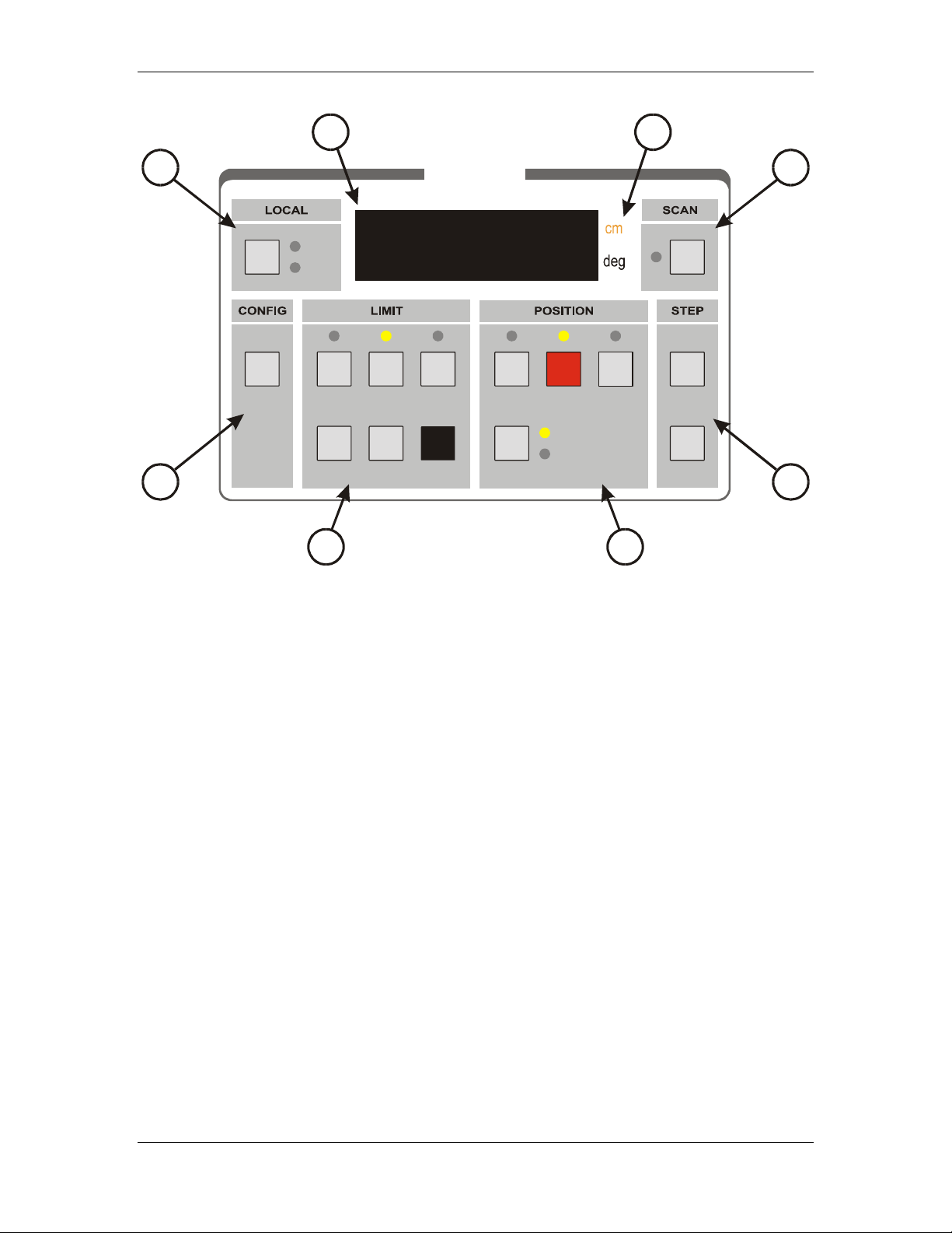
Figure 2 Model 2090 Device Control Block
1. LOCAL KEY AND INDICATORS
LOCAL key – The LOCAL key is a multi-function key
which has a different behavior depending on the status of
the Model 2090.
a. Pressing the LOCAL key while the corresponding
primary device is in remote control mode (RMT
indicator lit) will return the controller to local control
mode.
b. For a variable speed device, pressing the LOCAL key
while in local mode and viewing the position displays
will activate the speed selection mode, causing the
current speed selection to be displayed momentarily in
the primary display. The INCRM and DECRM keys
can then be used to adjust the speed selection.
©ETS-Lindgren, April 2006 21
Revision G– P#399199
Page 22

Preparation for Use Model 2090 Multi-Device Controller
c. In edit mode (see below), pressing the LOCAL key
will shift the display digit being edited to the next
higher digit.
RMT (REMOTE) indicator – This indicator will be lit as
long as the corresponding primary device is under remote
GPIB control. The front panel keys (except the LOCAL
key) of this primary device will be disabled while in remote
mode.
NOTE: While user input and control is disabled, the
remaining keys may still be used to acknowledge an error
condition while in remote control mode.
ADDR (ADDRESSED) indicator – This indicator will
strobe to indicate GPIB bus activity while in remote control
mode.
2. CONFIGURATION
PARAM (PARAMETER) key – Pressing this key will
stop all device motion and display the current entry of the
configuration parameter list for this primary device in the
corresponding display window. Repeatedly pressing this
key will advance to the next parameter in the list.
3. LIMIT KEYS AND INDICATORS
UP/CW key – Pressing this key will display the upper limit
for the current polarization of a tower, or the clockwise
limit of a turntable, reverberation paddle, or MAPS in the
corresponding numerical display.
UP/CW indicator – Lights to indicate that the numerical
display represents the upper limit of a tower, or the
clockwise limit of a turntable, reverberation paddle, or
MAPS.
22 © ETS-Lindgren– April, 2006
Revision G– P# 399199
Page 23

Model 2090 Multi-Device Controller
CURRENT POSITION key – Pressing this key will
display the current position of the primary device in the
corresponding display.
CURRENT POSITION indicator – Lights to indicate that
the numerical display represents the current position of the
primary device. This is the default state.
DOWN/CCW key – Pressing this key will display the
upper limit for the current polarization of a tower, or the
counterclockwise limit of a turntable, reverberation paddle,
or MAPS in the corresponding display.
DOWN/CCW indicator – Lights to indicate that the
numerical display represents the lower limit of a tower, or
the counterclockwise limit of a turntable, reverberation
paddle, or MAPS.
ENTER key – Pressing this key toggles the edit mode on
or off. With the edit mode off, pressing ENTER will
initiate edit mode for the currently displayed limit or
parameter. Pressing ENTER while in edit mode will store
the modified limit or parameter and exit edit mode.
NOTE: This key only works when the device is not in
motion.
INCRM (INCREMENT) key – Pressing this key will
increment the currently highlighted digit of the limit,
position, parameter, or speed selection in the display
window. For limits, position, and parameters, if the Model
2090 is not already in edit mode, it will automatically
switch to edit mode.
NOTE: With the exception of changing the speed selection,
this key only works when the device is not in motion.
DECRM (DECREMENT) key – Pressing this key will
decrement the currently highlighted digit of the limit,
©ETS-Lindgren, April 2006 23
Revision G– P#399199
Page 24

Preparation for Use Model 2090 Multi-Device Controller
position, parameter, or speed selection in the display
window. For limits, position, and parameters, if the Model
2090 is not already in edit mode, it will automatically
switch to edit mode.
NOTE: With the exception of changing the speed selection,
this key only works when the device is not in motion.
4. POSITION KEYS AND INDICATORS
UP/CW key – Pressing this key will command the
associated primary device to move in the UP or
CLOCKWISE direction. Actual motion will depend on the
current state of the device and the controller.
UP/CW indicator – Lights solid to indicate that the device
is moving in the UP or CLOCKWISE direction. Flashes to
acknowledge user key-press of the UP/CW key and to
indicate that the target motion is in the UP or
CLOCKWISE direction during reverse delay operations.
STOP key – Pressing this key will command the
associated primary device to stop motion. Variable speed
devices will decelerate to their minimum speed before
disabling the drive.
STOP indicator – Lights solid to indicate that the device
is stopped. Flashes to acknowledge user key-press of the
STOP key and during deceleration of variable speed
devices.
DOWN/CCW key – Pressing this key will command the
associated primary device to move in the DOWN or
COUNTERCLOCKWISE direction. Actual motion will
depend on the current state of the device and the controller.
DOWN/CCW indicator – Lights solid to indicate that the
device is moving in the DOWN or COUNTER-
24 © ETS-Lindgren– April, 2006
Revision G– P# 399199
Page 25

Model 2090 Multi-Device Controller
CLOCKWISE direction. Flashes to acknowledge user keypress of the DOWN/CCW key and to indicate that the
target motion is in the DOWN or COUNTERCLOCKWISE direction during reverse delay operations.
POLARIZATION/FLOAT/SPEED key – This key has a
variety of behaviors depending on the attached primary
device type:
a. For towers, pressing this key toggles the tower boom
between horizontal and vertical polarization when the
display shows the current position; and toggles the
display between horizontal and vertical limit displays
when showing an upper or lower limit.
b. For air-flotation turntables, pressing this key floats or
lowers the turntable on its air cushions. The turntable
cannot be dropped while in motion.
c. For two speed turntables, pressing this key toggles the
turntable between fast and slow speed.
d. For standard variable speed turntables, pressing this key
advances the selected speed setting to the next preset
speed selection.
HOR/UP/FAST indicator – This indicator has a variety of
behaviors depending on the attached primary device type:
a. For towers, this indicator lights solid to indicate that the
tower is polarized horizontally. This indicates the
status of the polarization solenoid only, and may or may
not reflect the actual position of the tower’s cross boom
at any given instant. This indicator flashes to indicate
that the display is showing the upper or lower limit for
the horizontal polarization, while the tower is still
polarized vertically.
©ETS-Lindgren, April 2006 25
Revision G– P#399199
Page 26

Preparation for Use Model 2090 Multi-Device Controller
b. For air-flotation turntables, this indicator lights solid to
show that the air flotation solenoid has been activated.
c. For two speed turntables, this indicator lights solid to
show that the turntable motor is set to high speed.
d. For standard variable speed turntables, this indicator
lights in a binary fashion with the VERT/DN/SLOW
indicator to represent the least significant bits of the
current speed selection. See the section on
“OPERATION” for more information on this display.
VERT/DN/SLOW indicator – This indicator has a variety
of behaviors depending on the attached primary device
type:
e. For towers, this indicator lights solid to indicate that the
tower is polarized vertically. This indicates the status
of the polarization solenoid only, and may or may not
reflect the actual position of the tower’s cross boom at
any given instant. This indicator flashes to indicate that
the display is showing the upper or lower limit for the
vertical polarization, while the tower is still polarized
horizontally.
f. For air-flotation turntables, this indicator lights solid to
show that the air flotation solenoid has been deactivated.
g. For two speed turntables, this indicator lights solid to
show that the turntable motor is set to low speed.
h. For standard variable speed turntables, this indicator
lights in a binary fashion with the HOR/UP/FAST
indicator to represent the least significant bits of the
current speed selection. See the section on
“OPERATION” for more information on this display.
26 © ETS-Lindgren– April, 2006
Revision G– P# 399199
Page 27

Model 2090 Multi-Device Controller
5. STEP KEYS
INC (INCREASE) key – This key has two functions:
a. Pressing this key while viewing position information
will command the associated primary device to move
in the UP or CLOCKWISE direction until the key is
released. Actual motion will depend on the current
state of the device and the controller.
b. Pressing this key while viewing the parameter list will
move up the parameter list by one entry, allowing the
user to scroll back through the parameter list.
DEC (DECREASE) key – This key has two functions:
a. Pressing this key while viewing position information
will command the associated primary device to move in
the DOWN or COUNTERCLOCKWISE direction until
the key is released. Actual motion will depend on the
current state of the device and the controller.
b. Pressing this key while viewing the parameter list will
move down the parameter list by one entry, allowing
the user to scroll forward through the parameter list
(same as pressing the PARAM key).
6. SCAN KEY AND INDICATOR
SCAN key – This key toggles the scan mode on or off.
When activated, the associated primary device will move
between the upper/clockwise and lower/counterclockwise
limits for the number of cycles specified by the scan cycle
parameter,
P3. See the “MODEL 2090 PARAMETER
LIST” for more information.
SCAN indicator – This indicator is lit as long as the scan
mode is activated.
©ETS-Lindgren, April 2006 27
Revision G– P#399199
Page 28

Preparation for Use Model 2090 Multi-Device Controller
7. UNIT INDICATORS
cm indicator – This indicator is lit for devices configured
as towers, to indicate that the position and limit information
is displayed in centimeters.
deg indicator – This indicator is lit for devices configured
as turntables, to indicate that the position and limit
information is displayed in degrees.
8. PRIMARY DISPLAY
This five digit, seven-segment display provides the primary
feedback for the user interface. It is used to display current
position information, limit settings, parameter settings,
speed selection, error messages, and other alphanumeric
messages.
28 © ETS-Lindgren– April, 2006
Revision G– P# 399199
Page 29

Model 2090 Multi-Device Controller Model 2090 Multi-Device Controller
STANDARD BACK PANEL DESCRIPTION
LINE INPUT
FUSE
2 A: 250 V T
115/230 V
50/ 60 Hz
100 VA MAX.
IEEE 488
-
GPIB
CAUTION
For laborator y use by
qualified per sonnel.
ATTENT ION
Pour emploi par le
personnel de labora toire.
AUXILIARY CONTROL
AUX 1 AUX 2
AUX 3 AUX 4
DEVICE INTERFACE
DEVICE 2
IN IN
OUT OUT
DEVICE 1
1
2
Figure
3 4 5 6
3 Model 2090 Standard Back Panel
1. AC POWER FUSE – This is the AC power fuse holder.
Replace the fuse with the power off and the power cord
disconnected from the unit, and only with a fuse of the
same rating. Failure to do so may cause personal injury or
instrument damage and will void the warranty.
2. ER INLET – This is the IEC 320 power inlet.
IEC POW
Attach an appropriate power cord between this inlet and the
power mains. This is a grounded outlet and provides the
safety earth ground for the instrument. Never attempt to
defeat the safety features of the device. Doing so may cause
personal injury or instrument damage and will void the
warranty.
3.
GPIB PORT – This is the IEEE 488 GPIB interface port.
It is used to connect the Model 2090 to a PC
or other GPIB
bus controlling device using a standard GPIB cable.
4.
AUXILIARY CONTROL – These are the ST-type fiber
optic output connectors for the four auxiliary device
©ETS-Lindgren, April 2006 29
©ETS-Lindgren, April 2006 29
Revision G– P#399199
Revision G– P#399199
Page 30

Preparation for Use Model 2090 Multi-Device Controller
controls. They provide simple on/off control for remote
devices fitted with an auxiliary device input.
5.
6.
DEVICE 2 INTERFACE – These are the ST-type fiber
optic I/O co
nnectors for primary device number two. One
channel of a duplex fiber optic cable connects from the
OUT connector of the controller to the IN connector of the
primary interface of a device (tower, turntable, e
cond channel connects from the OUT connector of the
se
tc.). The
primary interface of the device to the IN connector of the
controller.
NOTE: Older motor base designs do not have a secondary
fiber optic interface. The secondary interface on newer
devices is currently reserved for future expansion.
DEVICE 1 INTERFACE – These are the ST-type fiber
optic I/O co
nnectors for primary device number one. One
channel of a duplex fiber optic cable connects from the
OUT connector of the controller to the IN connector of the
primary interface of a device (tower, turntable, e
tc.). The
second channel connects from the OUT connector of the
primary interface of the device to the IN connector of the
controller.
NOTE: Older motor base designs do not have a secondary
fiber optic interface. The secondary interface on newer
devices is currently reserved for future expansion.
30 © ETS-Lindgren– April, 2006
Revision G– P# 399199
Page 31

Model 2090 Multi-Device Controller
A
OPTIONAL BACK PANEL DESCRIPTION
uxiliary Control
Switches
NC C NO
NC C NO
NC C NO
SW 1
SW 2
SW 3
SW 4
Figure 4 Model 2090 Option 1 Back Panel
AUXILIARY CONTROL – Auxiliary devices use a single-pole double-throw RF relay to control simple
on/off operation. The connection type is SMA.
©ETS-Lindgren, April 2006 31
Revision G– P#399199
Page 32

Preparation for Use Model 2090 Multi-Device Controller
POWER REQUIREMENTS
The Model 2090 accepts any AC power source input within
the range of 115-230 VAC, 50/60 Hz. It is not necessary to
select a voltage. To apply AC power, use the threeconductor power cable that is shipped with the controller.
When connected from the IEC 320 power inlet to an
appropriate AC power source, the instrument chassis will
be connected to the earth ground.
CAUTION: Before switching on, connect the protective
earth terminal of this instrument to the protective conductor
of the power cord. The power cord should only be
connected to a socket outlet provided with a protective
earth contact. Do not use an extension cord without a
protective earth connector. Never attempt to defeat any
safety feature of an electrical device or serious injury may
result.
The Model 2090's configuration and current settings are
backed-up by non-volatile RAM (NVM). The NVM
retains these settings in the event of power loss or power
down. Three (3) AAA alkaline batteries, located internally,
are needed for this memory back up. Refer to the
procedure in the section “NVRAM Battery Backup” in
Appendix B: Maintenance, for more information on
replacing these batteries.
NOTE: It is recommended that the batteries be replaced
annually to reduce the risk of potential memory loss.
32 © ETS-Lindgren– April, 2006
Revision G– P# 399199
Page 33

Model 2090 Multi-Device Controller
RACK MOUNTING
DEVICE CONNECTIONS
The Model 2090 controller can be ordered with a rack
mount option (Part # 540037). This option can be either
factory or field installed. The rack mount option provides
capability for installing the controller in a universal E. I. A.
48.26 cm (19.0 in) rack. A rack height of 13.34 cm (5.25
in) is required.
Any combination of primary devices (towers, turntables,
reverberation paddles, MAPS, etc.) can be connected to the
two Device Interface ports located on the rear panel of the
controller. For easy set up of an EMC facility, it is
recommended that the tower be connected to the Device 1
interface port and the turntable be connected to the Device
2 interface port, since these are the controller's default
settings. Reverberation paddles and each axis of the MultiAxis Positioner behave similar to turntables, and should be
configured as such. Primary device connection is
accomplished by way of a dual fiber cable included with
the device. This cable terminates into two ST connectors
that are identical at both ends. The cable is symmetrical;
either end can be connected to the controller. A fiber optic
cable that is connected to the IN port of a device should, at
the other end, be connected to the primary OUT port of the
motor base. A fiber connected to the OUT port of the
device should, at the other end, be connected to the primary
IN port of the motor base. Older motor base designs have
only one fiber optic connector pair, while the newest motor
©ETS-Lindgren, April 2006 33
Revision G– P#399199
Page 34

Preparation for Use Model 2090 Multi-Device Controller
base interface provides a secondary interface reserved for
future expansion.
Additional devices (for example: Remote Air Polarized
Tripods, LISNs, EUTs, etc.) can be connected in any
sequence to the four Auxiliary Control Ports (located on the
rear panel). If there are less than four auxiliary devices
connected to the controller, it is recommended (not
required) that these devices be connected in numerical
order, starting with the Auxiliary Control Port 1. The
Auxiliary Ports are also standard ST fiber optic connectors.
Auxiliary Port Enabled products, such as air polarized
tripods, are provided with a single fiber cable with ST
connectors at both ends. Either end may be attached to the
2090.
NOTE: Fiber optic cabling for each device should not be
allowed to hang unsupported from the rear panel of this
controller. The fibers and connectors are easily broken if
twisted or bent too much. Keep the fiber optic cables as
straight as possible from the connector to the protective
sheath.
34 © ETS-Lindgren– April, 2006
Revision G– P# 399199
Page 35

Model 2090 Multi-Device Controller
OPTIONAL DEVICE CONNECTIONS
SW 1
NC C NO
NC C NO
NC C NO
Auxiliary devices use a single-pole, double-throw RF relay to
control simple on/off operation. The connection type is SMA.
SW 2
Additional devices (for example: CMU, Analyzers, dual
polarized horn antennas, etc.).
SW 3
SW 4
©ETS-Lindgren, April 2006 35
Revision G– P#399199
Page 36

Preparation for Use Model 2090 Multi-Device Controller
GPIB INTERCONNECTIONS
The Model 2090 is compatible with the General Purpose
Interface Bus as described in the IEEE 488.1/488.2
standard. A "D" connector has been provided on the 2090
rear panel for connection to a GPIB bus.
NOTE: When making this connection, do not stack more
than three cables on any one connector. This eliminates
undue mechanical stress on the connector and rear panel.
Also, be sure to screw the two-connector lock-screws finger
tight to avoid a loose connection during operation.
NOTE: The controller's talker/listener bus address can be
set through the front panel. Instructions on how to perform
this operation may be found in “Initialization” under the
subsection “Configuring For Use”.
36 © ETS-Lindgren– April, 2006
Revision G– P# 399199
Page 37

Model 2090 Multi-Device Controller
INITIALIZATION
STARTUP
The devices that will be controlled by the Model 2090 must
be properly connected to the controller before applying
power to the unit. If nothing is connected to the Model
2090 when power is applied the Device One and Device
Two displays will show dashes (-----).
The Model 2090 controller has a power-up diagnostic/selftest to check for internal problems found during
initialization. During this period, the all display indicators
will flash on for several seconds to allow a visual
inspection, and then the firmware revision number will be
displayed in the left-hand (Device One) display window as
r X.XX where X.XX is the version number. If an internal
error is found during the startup sequence, an error message
"EXXX" will appear in the Device One display, where
XXX is the error code.
©ETS-Lindgren, April 2006 37
Revision G– P#399199
Page 38

Initialization Model 2090 Multi-Device Controller
RECOVERABLE ERRORS:
The following errors indicate a recoverable problem that
may require user intervention. These errors can be cleared
by pressing any key on the front panel to acknowledge the
error. These errors can also be cleared remotely through
the GPIB Status reporting structure described in the
section “USING THE GPIB COMMAND SET WITH THE
MODEL 2090” subsection “GPIB Status Reporting”.
E001
E100
E101
E102
E103
E104
NVM Initialization Error. Parameter settings were lost
and restored to factory defaults. This error usually
indicates that the NVM backup batteries are dead and
should be replaced. See the procedure in the section
“NVRAM Battery Backup” in Appendix B:
Maintenance, for more information.
SYSTEM TEST FAILURES:
The following errors are of a more serious nature and may
indicate that service is needed. In the event of such an
error, power off the unit for several seconds and power it
back on. If the error recurs, contact ETS for service.
ROM test error: ROM has been detected as being
corrupt.
RAM test error: RAM has been detected as being
corrupt.
NVM test error: NVM has been detected as being
corrupt.
Low Power Test error: Power test failed.
GPIB Test error: GPIB test failed.
38 © ETS-Lindgren– April, 2006
Revision G– P# 399199
Page 39

Model 2090 Multi-Device Controller
HARDWARE ERRORS:
The following errors are not limited to the startup process,
and should not occur under normal operation. In the event
of such an error, power off the unit for several seconds and
power it back on. If the error recurs, contact ETS for
service.
E996
E997
E998
E999
BERR Error
Uninitialized Interrupt
Spurious Interrupt
Invalid Interrupt Error
Refer to “Appendix B” for more information on error
conditions and possible causes.
©ETS-Lindgren, April 2006 39
Revision G– P#399199
Page 40

Initialization Model 2090 Multi-Device Controller
EDITING PARAMETERS
The Model 2090 provides a versatile user interface for
editing configuration parameters, limits, and the current
position, by allowing several keys to perform multiple
duties. Prior to editing any settings, all device motion
should be stopped. The Model 2090 will automatically
stop device motion when configuration parameters are
displayed, and prevent the editing of limit and position
values while in motion, but the user should avoid
attempting to modify these values while equiptment is in
motion to avoid unexpected results.
To edit the limits or current position settings, select the
appropriate limit or position by pressing the corresponding
button under the LIMIT key group. The associated
indicator should light and the display will show the
corresponding value. For a tower, the 2090 provides two
sets of limits, one for horizontal polarization and one for
vertical, in order to protect antenna elements from damage
due to accidental polarization at the top or bottom of the
mast. Pressing the POLARIZATION key while the upper
or lower limit is displayed will switch the display to show
the corresponding limit for the opposite polarization,
without changing the tower polarization. To indicate
that the displayed value and polarization is not the current
polarization, the indicator light by the POLARIZATION
key will flash on and off. While in this state, the limit can
be changed using the limit edit keys just the same as any
other parameter.
40 © ETS-Lindgren– April, 2006
Revision G– P# 399199
Page 41

Model 2090 Multi-Device Controller
NOTE: In order to toggle the polarization of the tower from
the front panel, the display must be showing the current
position, and not either limit.
To edit a configuration parameter, press the PARAM key
to display the current parameter. Pressing the PARAM key
repeatedly will scroll down through the parameter list,
showing each parameter in turn. While viewing a
parameter, the STEP keys (INC/DEC) may be used to
scroll up or down the parameter list. This reduces the effort
necessary to scan through a long parameter list using the
PARAM key. Pressing any of the LIMIT/POSITION
selection keys will return the display to that selection.
Pressing any of the remaining motion keys will return the
display to the current position and execute that motion.
Pressing the PARAM key again will return to the last
displayed parameter in the list, allowing easy transition
between parameter adjustment and device operation.
Once the desired limit, position or parameter is visible in
the display window, pressing INCRM, DECRM, or
ENTER will toggle into edit mode. The lowest adjustable
digit will flash on and off. Pressing the LOCAL key for
that device will switch the flashing digit to the next higher
digit. In this way, it is possible to rapidly adjust any digit
of a multi-digit parameter or limit.
NOTE: Some parameters only have one digit, or a fixed
range of selections. For those parameters, such as bore
sight separation distance, the whole entry to be changed
will flash. Other parameters consist of single on/off toggles
©ETS-Lindgren, April 2006 41
Revision G– P#399199
Page 42

Initialization Model 2090 Multi-Device Controller
or activate specific controller functions. The edit behavior
of these parameters is described in the parameter table.
Using the LOCAL key to select the appropriate digit and
the INCRM and DECRM key to adjust the setting, any
value can be entered quickly. Once the desired value is
shown in the display, pressing ENTER will store the new
value. Pressing any key other than LOCAL, INCRM,
DECRM, or ENTER will exit the edit mode without
saving the value and perform the action associated with that
key.
When editing limits or the current position setting, the 2090
will not allow the current position to be set outside the
software limits, nor can the upper or lower limits be
adjusted below or above, respectively, the current position
or each other.
42 © ETS-Lindgren– April, 2006
Revision G– P# 399199
Page 43

Model 2090 Multi-Device Controller
CONFIGURING FOR USE
Before using the Model 2090, it must be configured to
match the primary devices connected to it. To the Model
2090, all primary devices are generic motor bases, with the
ability to move in two directions, report an encoder
position, and perform a few other basic functions. To
activate behavior specific to a certain type of device, i.e. a
bore sight tower or a two-speed turntable, it is necessary to
enter additional information into the Model 2090’s
configuration parameters table. The previous section
describes the process for entering these parameters. This
section describes each parameter and their typical settings.
The default factory preset configuration is given below.
2090 Default Configuration:
Parameter Value Description
P1
P2
P3
P4
P5
P8
P9
B1
S0
S1
S2
S3
S4
S5
S6
S7
S8
Oc
ACC
c
1
0
000
00
0
0.5
8
000
2000
-1
31
63
95
127
159
191
223
255
On
2.0
Tower
Standard (non-bore sight) tower
Infinite scan count
0 cm polarization offset
Standard bore sight correction
0.5 second reverse delay
Primary GPIB address 8
User options disabled
2000 encoder counts per meter
Step speed = run speed
Speed 1 ~12.5% of max speed
Speed 2 ~25% of max speed
Speed 3 ~37.5% of max speed
Speed 4 ~50% of max speed
Speed 5 ~62.5% of max speed
Speed 6 ~75% of max speed
Speed 7 ~87.5% of max speed
Speed 8 = max speed
Overshoot compensation enabled
Acceleration = 2 seconds
©ETS-Lindgren, April 2006 43
Revision G– P#399199
Page 44

Initialization Model 2090 Multi-Device Controller
SND
1
Remote sounds enabled
Lower Limit: 050.0 cm
Upper Limit: 400.0 cm
Current Position: 100.0 cm
Parameter Value Description
P1
P2
P3
P5
P8
P9
b1
S0
S1
S2
S3
S4
S5
S6
S7
S8
Oc
ACC
SND
c
0
0
000
1
2.5
9
000
3600
-1
31
63
95
127
159
191
223
255
On
2.0
1
Turntable
Standard turntable
Infinite scan count
Non-continuous rotation
2.5 second reverse delay
Primary GPIB address 9
User options disabled
3600 encoder counts per meter
Step speed = run speed
Speed 1 ~12.5% of max speed
Speed 2 ~25% of max speed
Speed 3 ~37.5% of max speed
Speed 4 ~50% of max speed
Speed 5 ~62.5% of max speed
Speed 6 ~75% of max speed
Speed 7 ~87.5% of max speed
Speed 8 = max speed
Overshoot compensation enabled
Acceleration = 2 seconds
Remote sounds enabled
CCW Limit: 000.0 degrees
CW Limit: 360.0 degrees
Current Position: 180.0 degrees
44 © ETS-Lindgren– April, 2006
Revision G– P# 399199
Page 45

Model 2090 Multi-Device Controller
MODEL 2090 PARAMETER LIST
The following table describes each parameter and the
available settings. In general, the term “tower” will be used
to refer to any linear positioning device, and the term
“turntable” will refer to any rotational positioner.
Parameter Description
Refers to the principal type of device to be controlled:
P1
P2
P3
0 = Turntable, Reverberation Paddle, MAPS, or other rotational
positioner.
1 = Tower or other linear positioner.
Refers to model specific features of device to be controlled:
0 = Standard Turntable / Tower
1 = Air Flotation Turntable / Bore Sight Tower
2 = Two Speed Turntable
NOTE: Parameter P2 for a turntable no longer supports a setting 3 =
Variable Speed Turntable/Tuner, which was introduced in V 2.25.
Instead, the 2090 now checks what type of motor base is attached and
automatically enables variable speed if it is available.
Refers to SCAN cycle count in full cycles:
1-999 = Number of complete circuits to perform from one limit
to the other and back again.
000 = Infinite scan count; scan mode does not automatically
terminate.
The Model 2090 also supports a half-cycle scan count through the
GPIB interface.
©ETS-Lindgren, April 2006 45
Revision G– P#399199
Page 46

Model 2090 Parameter List Model 2090 Multi-Device Controller
Refers to two different tower corrections, depending on the tower
P4
type:
For a standard tower, this value represents the polarization offset, in
the range of ±50 cm, applied to the tower position reading when the
polarization is changed. This parameter allows for correction of the
antenna height changed caused when centerline rotation is not
available or not in use.
For a bore sight tower, this parameter is used to enter the bore sight
separation distance corresponding to the configuration of the tower.
This value can be 3, 10, or 30 meters, and configures the 2090 to
correct for the difference in height between the carrier position and
the actual antenna position.
For bore sight towers, refers to the bore sight mast height correction:
P5
0 = Standard bore sight towers
1 = Custom or alternate bore sight tower
Currently, all six-meter tall 2070 series bore sight towers use the
default correction table. The alternate selection provides a correction
table for a shorter five-meter tower with a different cam mechanism.
In future revisions, the 2090 may provide support for other bore sight
tower designs either by adding additional tables or by allowing the
user to download the appropriate correction table for the attached
tower.
For turntables, refers to turntable rotation mode:
0 = Continuous
1 = Non-continuous
In the continuous mode of operation a turntable is allowed unlimited
movement. The counter readout is from 0 to 359.9 and the software
limits are ignored in this mode of operation. This is the desired
setting for reverberation paddles.
NOTE: For turntables equipped with hardware limits, they must be
disengaged for this mode to work correctly.
In the non-continuous mode, the turntable motion is restricted
between the upper and lower software limits. These limits are
adjustable between –999.9 to 999.9.
46 © ETS-Lindgren– April, 2006
Revision G– P# 399199
Page 47

Model 2090 Multi-Device Controller
Refers to the motor reverse delay, in seconds. This parameter allows
P8
setting the reverse delay used between direction changes. This is the
period of time for which the motor must remain off before allowing it
to move in the other direction. For split-phase motors, it is critical
that the motor come to a complete stop prior to reversing direction, or
the motor will continue moving in the same direction and cause a
Moving Wrong Direction error (
damage may be caused to the motor or device from reversing the
motor too quickly. This parameter should be used with care. If in
doubt use the factory default setting.
Refers to the primary GPIB address for each device. Valid values are
P9
in the range from 1 to 30 (0 is normally reserved for the controller in
charge; i.e. the computer). Each device must have a unique GPIB
address.
Refers to bit-wise parameter number one. This parameter provides
b1
selective enabling of several customizable parameters. The bits are
displayed in increasing order from right to left. Unless otherwise
indicated, a value of 0 indicates that the option is disabled and a value
of 1 indicates it is enabled. The two bits currently defined for
Refers to the encoder calibration parameter. This setting is used to
C
convert the encoder count values returned from a motor base into the
corresponding centimeter or degree position reading. For towers, the
number represents the number of encoder counts per meter. For
turntables, it represents the number of counts per revolution. Using
this parameter, a variety of standard, retrofit, and custom devices can
be used. The settings for various products are listed below:
E004). For other motors, physical
b1 are:
Bit 0 – Limits STEP controls (INC/DEC) to only allow motion
within the soft limits instead of the hardware limits of
the motor base.
Bit 1 – Provides a quick stop option for the STEP controls
(INC/DEC) on variable speed devices. Enabling this
bit (setting it to 1) will bypass the deceleration ramp on
variable speed motor bases, stopping them as quickly as
possible. NOTE: This option should be used with
caution, since it is possible to cause damage to the
device or equipment attached to the device.
Model 2075 Mini-Mast: 1620
All other EMCO 2070 series towers: 2000
Model 2065 LoPro Turntable: 3665
©ETS-Lindgren, April 2006 47
Revision G– P#399199
Page 48

Model 2090 Parameter List Model 2090 Multi-Device Controller
g
Model 2081 Turntables: 3608
Model 2088 EuroPro Turntable: 4500*
Model 5901 Mode Tuner: 6000**
Multi-Axis Positioning System: 4500
All other model 2060/2080 series turntables: 3600
All other current ETS-Lindgren rotational devices:3600
*Early revisions of the Model 2088 used 4750 for the Euroshield
versions and 4800 for the U.S. version.
**Early revisions of the Model 5901 Mode Tuner used 6400.
If the device is not listed, or the given value does not appear to work
correctly, the encoder calibration value can be determined using the
following procedure:
FOR TOWERS,
1. Set the encoder calibration value to 1000.
2. Insure that the tower is positioned to allow at least a meter
of travel in the upward direction at an easily measurable
height, and then set the current position reading to 000.0.
NOTE: It will be necessary to adjust the lower limit setting
to allow this.
3. Using the STEP keys, adjust the height of the carrier until it
is one meter above the start point.
4. Record the reading of the display, ignoring the decimal
point (i.e. 200.0 would be 2000). This is the encoder
calibration value. NOTE: If the value is below 1000, the
resolution of the encoder is low and thus the 2090 will not
provide 0.1 cm resolution, even though the display shows
that digit. If the value has gone past 9999, the encoder has
too many counts per meter and the 2090 can not correct for
it. In this case, contact ETS for assistance.
5. Enter this value for the encoder calibration value and reset
the limits and position information.
6. Test the tower by moving it a known distance and
comparing the display to the measured distance traveled. It
may be necessary to adjust the encoder calibration value up
or down slightly depending on the result.
FOR TURNTABLES,
1. Set the encoder calibration value to 3600.
2. Insure that the turntable is positioned to allow more than a
full revolution of travel in the clockwise direction and use
the STEP keys to run the turntable clockwise a few degrees
to remove any play in the table.
3. Mark the current location of the turntable a
ainst the ground
48 © ETS-Lindgren– April, 2006
Revision G– P# 399199
Page 49

Model 2090 Multi-Device Controller
Refers to the speed setting for variable speed devices when the STEP
S0
(INC/DEC) keys are used.
This parameter is only visible for variable speed devices. See the
next entry for more information on speed settings.
ring (masking tape works well), and set the current position
reading to 000.0.
4. Using the STEP keys, rotate the turntable clockwise until it
is again aligned with the mark on the ground ring. For best
results, the last motion should always be in the clockwise
direction to insure that any play in the gearing between the
motor and encoder is accounted for.
5. Record the reading of the display, ignoring the decimal
point (i.e. 360.0 would be 3600). This is the encoder
calibration value. NOTE: If the value is below 3600, the
resolution of the encoder is low and thus the 2090 will not
provide 0.1 degree resolution, even though the display
shows that digit. If the value has gone past 9999, the
encoder has too many counts per meter and the 2090 can
not correct for it. In this case, contact ETS for assistance.
6. Enter this value for the encoder calibration value and reset
the limits and position information.
7. Test the turntable by moving it a complete revolution and
comparing the alignment marks. It may be necessary to
adjust the encoder calibration value up or down slightly
depending on the result. NOTE: When scanning between
limits, it is not uncommon to have a small discrepancy
between the absolute position of the table and the display on
the 2090. This is because reversing the direction of rotation
reverses any gear play between the encoder and the table
top, allowing that play to be visible in the positioning
accuracy.
-1 Disabled. The STEP keys will cause the device to
move at the same speed as the other motion keys.
0-255 Defines the speed setting for motion caused from
the STEP keys. This allows the STEP keys to be
used for fine adjustment at a constant speed, while
having all other motion governed by the selected
speed setting.
©ETS-Lindgren, April 2006 49
Revision G– P#399199
Page 50

Model 2090 Parameter List Model 2090 Multi-Device Controller
Refers to the eight possible preset speed settings for variable speed
S1-S8
devices. Each of these parameters can be set to any value from 0 to
255, with the resulting device speed being given approximately by
the formula:
Speed = N (MaxSpeed – MinSpeed) / 255 + MinSpeed
Where N is the speed setting from 0 to 255.
Each speed setting has its own individual overshoot compensation
value to provide proper overshoot correction for each speed selection.
However, the new ramp control provided by the 2090 and the
enhanced MB-IV motor base firmware will normally make overshoot
compensation unnecessary. The device will decelerate prior to
reaching the target value and creep in at the minimum speed.
NOTE: It is the nature of variable speed drives that there is a
minimum speed at which the motor will operate. All ETS-Lindgren
variable speed devices are factory adjusted to insure that the device
will be able to operate properly in this range under normal load
conditions. However, under heavy load or other unexpected
conditions, it may be necessary to increase the minimum speed
settings. Below this setting, the motor will not be able to cause
WARRANTY
rotation, but will be active until a Motor Not Moving error (E002)
occurs. WARNING: Never operate any device in a stalled
condition. Doing so can cause damage to the drive unit and will
invalidate the warranty! Always insure that the minimum speed
setting specified in the S0-S8 parameters is above the minimum value
at which the device will operate under normal load.
These parameters are only visible for variable speed devices.
Invokes the Parameter Clear menu option. Pressing the ENTER key
PCLr
will display
SURE in the display. Pressing ENTER a second time
will clear the parameters for this device to their factory defaults.
Pressing any other key will abort the operation and perform the
associated action.
50 © ETS-Lindgren– April, 2006
Revision G– P# 399199
Page 51

Model 2090 Multi-Device Controller
Invokes the Overshoot Clear menu option. Pressing the ENTER key
OSCLr
will display SURE in the display. Pressing ENTER a second time
will clear the overshoot compensation values for this device.
Pressing any other key will abort the operation and perform the
associated action.
On occasion, certain motion error conditions, such as hardware limit
hit (E005), can cause the overshoot compensation values to become
corrupted, resulting in erratic behavior. The most common symptom
of this is that each time the device is commanded to move it will
move halfway to the target and stop. At this point, the automatic
updating of the overshoot compensation values is overridden and can
only be corrected by manually clearing the values. Once cleared, the
normal overshoot compensation will be restored after several motion
cycles of the device.
Refers to the Overshoot Compensation Enable/Disable parameter.
OC
Pressing the INCRM and DECRM keys will toggle this between
overshoot compensation being on or off. Pressing the ENTER key
On/OFF
will save the selected setting.
For variable speed devices with creep capability, overshoot
compensation is not needed and will interfere with normal table
operation in the case of occasional overshoot events. Also, some
software designed to work with older ETS-Lindgren controllers
provide their own form of overshoot compensation. This can
typically be disabled within the software to allow the 2090 to control
overshoot compensation, but this parameter can also be used to allow
the software to provide the compensation instead.
©ETS-Lindgren, April 2006 51
Revision G– P#399199
Page 52

Model 2090 Parameter List Model 2090 Multi-Device Controller
Invokes the Zero Reference menu option. Pressing the ENTER key
ZERO
will display
SURE in the display. Pressing ENTER a second time will
initiate a zero search sequence. Pressing any other key will abort the
operation and perform the associated action.
Once initiated, the search sequence will move the device in the
DOWN/CCW direction until the zero point is detected. The current
position setting is then adjusted to represent the absolute position
with respect to the zero pulse. NOTE: Overshoot will normally result
in the displayed position being somewhat less than zero. This is
normal, and the position is correct. Pressing any motion control key,
or encountering a motion error while the sequence is in progress, will
abort the scan and return the device to normal operation.
This parameter is only available on motor bases that provide an
absolute zero reference pulse.
Provides the firmware version of the motor base for information
BASE
purposes only. Pressing the ENTER key will toggle between the
BASE parameter display and the motor base firmware version
number. The possible displays are as follows:
2090 Indicates older (pre-1997) motor base firmware,
which only supports standard up/down/polar
settings through a simple binary communication
protocol. (MB-III)
HH Two digit hexadecimal number – Indicates 2190
compatible motor base firmware. This firmware
provides more intelligent control from within the
motor base, reducing the communications
overhead between the motor base and controller.
(MB-III)
XX.XXx Decimal version number (of the form
1.07a, for
example) – Indicates the MB-IV motor base
interface board, which is capable of flash
upgrades and enhanced functionality.
Ennul Indicates the controller is in emulation mode.
This is the acceleration setting for variable speed devices. The
ACC
number setting represents the time in seconds for the positoiner to
reach full speed. For high inertial loads a longer acceleration time
might be required.
This displays the motor and control board temperatures denoted by
TEP
“a“ and “b“. Toggle between the two by pushing the INCRM and
DECRM buttons.
52 © ETS-Lindgren– April, 2006
Revision G– P# 399199
Page 53

Model 2090 Multi-Device Controller
This is the sound configuration setting for the motorbase speaker.
SND
The motorbase can output audible indications for errors, movement,
and remote control feedback. 0 = All sounds disabled, 1 = Key press
sounds enabled for hand control function, 2 = Error indications
enabled, 3 = Motion sounds enabled. With all sounds enabled the
motorbase will emit an audible noise if any error condition should
arise and a warning indication during movement.
Using the technique described previously, adjust the
necessary parameters so that they match the configuration
of the attached devices. Typical configurations are likely to
require adjusting parameters
P1, P2, and C at a minimum.
Bore sight towers will also require the setting of parameter
P4 to set the separation distance. The remaining
parameters are generally set to cover user preferences or
custom configurations.
NOTE: Do not change parameters of a device while
another device is in operation. Doing so will cause the
other device to stop motion.
Once the parameters have been configured for each device,
check and adjust the limits as necessary. Remember to
adjust the limits for both horizontal and vertical
polarizations on towers.
©ETS-Lindgren, April 2006 53
Revision G– P#399199
Page 54

Model 2090 Parameter List Model 2090 Multi-Device Controller
This page intentionally left blank.
54 © ETS-Lindgren– April, 2006
Revision G– P# 399199
Page 55

Model 2090 Multi-Device Controller
OPERATION
MANUAL OPERATIONS
The front panel of the Model 2090 provides the interface
for two separate and complete device controllers, each with
identical displays and function keys. By default, both
controllers are in manual (LOCAL) mode unless given any
command from a device on the GPIB bus (usually a
computer with a GPIB card installed). When in the remote
mode the RMT indicator light will remain on and the
ADDR indicator light will strobe with bus activity.
Pressing the LOCAL key, for Device 1 or 2, will return
only the specific device to local mode. Auxiliary devices
are always available from both the front panel of the Model
2090 and the GPIB interface, regardless of the remote or
local state of the primary devices.
In manual mode, the motion and behavior of the attached
devices can be controlled through the front panel user
interface. The front panel controls allow the user to move
the primary device in between software limits, either
continuously or momentarily in one direction, or to
automatically scan from one limit to the other and back
again. Where supported by the attached hardware, it also
allows the user to change device specific functions like
polarization, speed, and flotation state.
©ETS-Lindgren, April 2006 55
Revision G– P#399199
Page 56

Operation Model 2090 Multi-Device Controller
USING LOCAL FUNCTIONS
Pressing the LOCAL function key will cause the Model
2090 to exit remote mode, unless the unit has been
remotely set to the Remote With Lockout State (RWLS)
using the appropriate GPIB command codes (refer to the
documentation provided with the controlling GPIB device
for information on setting RWLS). When the controller
exits remote mode, it enters manual mode and remains
there until it receives the next GPIB command. Unless
given a GPIB command, the controller will automatically
be in the manual mode of operation. It is not possible to
enter remote mode by pressing the LOCAL key.
USING POSITION FUNCTIONS
While in manual mode, the POSITION keys control the
continuous motion of the attached device.
TO MOVE UP/CLOCKWISE
To initiate continuous motion in the upward or clockwise
direction, press the UP/CW key under the POSITION key
group. If the device is not moving and is below the
upper/clockwise software limit (viewed by pressing the
UP/CW key in the LIMIT group), the UP/CW indicator
will light and the device will start moving in that direction.
If the device is already moving in the same direction, it will
continue moving to the upper/clockwise soft limit. If the
device is moving in the opposite direction, the UP/CW
indicator light will flash to indicate that the 2090 has
recognized the command. The device will decelerate (if
56 © ETS-Lindgren– April, 2006
Revision G– P# 399199
Page 57

Model 2090 Multi-Device Controller
equipped with variable speed control) and then the STOP
motion indicator will illuminate for the Reverse Delay
period (see Parameter
P8) before moving in the requested
direction. At that point, the UP/CW indicator will light
solid. In all cases, motion will continue until the device
reaches the soft limit, the hardware limit (if equipped), or
until another motion command is issued.
TO MOVE DOWN/COUNTERCLOCKWISE
To initiate continuous motion in the downward or
counterclockwise direction, press the DOWN/CCW key
under the POSITION key group. If the device is not
moving and is above the lower/counterclockwise software
limit (viewed by pressing the DOWN/CCW key in the
LIMIT group), the DOWN/CCW indicator will light and
the device will start moving in that direction. If the device
is already moving in the same direction, it will continue
moving to the lower/counterclockwise soft limit. If the
device is moving in the opposite direction, the
DOWN/CCW indicator light will flash to indicate that the
2090 has recognized the command. The device will
decelerate (if equipped with variable speed control) and
then the STOP motion indicator will illuminate for the
Reverse Delay period (see Parameter
P8) before moving in
the requested direction. At that point, the DOWN/CCW
indicator will light solid. In all cases, motion will continue
until the device reaches the soft limit, the hardware limit (if
equipped), or until another motion command is issued.
©ETS-Lindgren, April 2006 57
Revision G– P#399199
Page 58

Operation Model 2090 Multi-Device Controller
TO STOP MOTION
To stop device motion, press the STOP key. The device
will decelerate (if equipped with variable speed control),
with the STOP motion indicator flashing to acknowledge
the key press, and then the motor drive will be disabled and
the STOP indicator will illuminate solid.
USING LIMIT FUNCTIONS
To set the lower/counterclockwise limit for the device
under control, press the DOWN/CCW key under LIMIT.
The indicator above this key will light. Set the limit by
pressing the INCRM and DECRM keys under LIMIT until
the desired limit is shown on the display. Then, press the
ENTER key. To set the upper/clockwise limit for the same
device press the UP/CW key under LIMIT. The indicator
light above this key will light. Set the limit by pressing the
INCRM and DECRM keys under LIMIT until the desired
limit is show on the display. Press the ENTER key. To
check the current position of the device under control press
the CURRENT POSITION key under LIMIT. The
indicator above this key will light and the device’s current
position will appear on the display.
NOTE: Two sets of upper and lower tower limits can be set
for horizontal and vertical antenna polarization. When
modifying these limits, keep in mind that only the limit of
the current polarization is being changed.
NOTE: The current position cannot be changed to a value
greater than the upper limit or less than the lower limit.
58 © ETS-Lindgren– April, 2006
Revision G– P# 399199
Page 59

Model 2090 Multi-Device Controller
USING THE SCAN FUNCTION
The lower limit must always be less than or equal to the
upper limit.
The SCAN key controls the cyclic motion of the attached
device. The SCAN function allows continuous scanning of
devices from one to an infinite number of cycles. The
SCAN function begins by moving to the closest limit, then,
from that point, the 2090 begins counting cycles. A cycle
is defined as movement from one limit to the other and
back again. The number of cycles that the device will
perform is defined in parameter
P3. The SCAN function
can be terminated by pressing the SCAN button a second
time (same behavior as pressing STOP) or by issuing any
other motion command.
©ETS-Lindgren, April 2006 59
Revision G– P#399199
Page 60

Operation Model 2090 Multi-Device Controller
USING THE STEP FUNCTIONS
The STEP functions can move a device in “momentary”
increments using the toggle keys under STEP. These keys
allow “jogging” the device to a more exact position. These
keys are as follows:
INC Moves the device up or clockwise.
DEC Moves the device down or counterclockwise.
The controller will move the device in the desired direction
as long as the key is pressed. When the key is released, the
device will stop. The corresponding motion indicators
under the POSITION control group will light to indicate
the actual motion. Under the default configuration, the
STEP keys are not restricted by the software limits. Thus
they can be used for adjusting position outside the soft limit
settings during configuration. Optionally, the Model 2090
can be configured to restrict the motion to stay within the
soft limits using parameter
b1. This parameter also allows
configuring the STEP keys to use a “fast stop” option on
variable speed devices, which will eliminate the normal
deceleration in favor of a much quicker deceleration curve.
This can be used to improve the jog response of a device
with a long deceleration. In addition, parameter
S0 can be
used to specify a fixed speed for use by the STEP keys.
CHANGING POLARIZATION
60 © ETS-Lindgren– April, 2006
Revision G– P# 399199
Page 61

Model 2090 Multi-Device Controller
For towers equipped with air polarization, pressing the
POLARIZATION key, while the current position is shown
in the display, will toggle the state of the air solenoid valve
in the motor base. The HOR or VERT indicator will light
to indicate the state of the solenoid. If the Polarization
Offset (parameter
P4 on a standard tower) is non-zero, the
value will be added or subtracted from the current position
depending on the target polarization. In moving from
horizontal to vertical polarization, the value will be
subtracted, since the antenna will rotate from being the
offset distance above the centerline of the boom to being
that distance to the side. In moving from vertical to
horizontal, the value will be added to the current position.
The actual motion of the polarization mechanism is
determined by various factors, including available air
pressure and flow control settings on the air polarization
piston cylinder. There is no feedback to indicate that the
cross boom has completed the polarization cycle. The user
should allow a certain amount of time for the polarization
cycle to complete before continuing testing, or use visual
feedback (i.e. from a camera system) to verify that the
polarization operation has completed.
If the current position at the target polarization is outside
the limits of the target polarization, the Model 2090 will
generate a Polarization Limits Violation (
E006) error and
not allow the tower to polarize. As described in the
configuration information, the Model 2090 provides two
sets of limits, one for each polarization, designed to protect
antenna elements from damage. (The Model 2090 provides
©ETS-Lindgren, April 2006 61
Revision G– P#399199
Page 62

Operation Model 2090 Multi-Device Controller
a small overshoot tolerance on this value, so, for example, a
current position of 99.5 will not cause an error when
switching to a polarization where the limit is 100.0.) Refer
to the section on “Editing Parameters” under
“Initialization” for information on checking or changing the
limits for the target polarization. In addition to a difference
in limits, the use of the Polarization Offset (
P4) on a
standard tower could make it so that the current position at
the target polarization is outside the limits, even though the
displayed current position is within the target limits. See
above for a description of the polarization offset.
NOTE: In order to toggle the polarization of the tower from
the front panel, the display must be showing the current
position, and not either limit.
NOTE: While the 2090 will allow the tower to be polarized
while in motion, it is strongly recommended that the device
only be polarized while stationary. The added stress on the
tower mechanism and the antennas increases the chance of
damage to both. Always insure that the applied weight and
overhung load of the antenna are within the specifications
of the tower prior to polarizing.
62 © ETS-Lindgren– April, 2006
Revision G– P# 399199
Page 63

Model 2090 Multi-Device Controller
POLARIZATION VIOLATION AND LIMITS
A common source of confusion is the Polarization Limits
Violation (
E006) ) designed to protect antenna elements
from damage. The 2090 allows the user or a program to set
separate limits for horizontal and vertical polarizations.
However, attempting to polarize the tower when the current
position is outside the limits for the target polarization will
generate a polarization violation. (The 2090 provides a
small overshoot tolerance on this value, so a current
position of 99.5 will not cause an error when switching to a
polarization where the limit is 100.0.) Previously, there
was no way to solve a polarization violation from the front
panel other than to move the tower carrier and try to
polarize again. The 2090 now supports a limit toggle
option that allows the user to inspect and adjust the limit
for the other polarization. While viewing either the upper
or lower limit (by pressing the UP or DOWN buttons under
LIMIT), pressing the POLARIZATION key will toggle the
display to show the corresponding limit for the other
polarization without changing the tower polarization. To
indicate that the displayed value and polarization is not the
current polarization, the indicator light by the
POLARIZATION key will flash on and off. While in this
state, the limit can be changed using the limit edit keys just
the same as any other parameter. In order to toggle the
polarization of the tower from the front panel, the display
must be showing the current position, and not either limit.
CHANGING SPEEDS
©ETS-Lindgren, April 2006 63
Revision G– P#399199
Page 64

Operation Model 2090 Multi-Device Controller
For two speed turntables, pressing the SPEED key will
toggle the speed control relay in the motor base. The
FAST or SLOW indicator will light to indicate the state of
the speed relay. The actual speed set by these two positions
is dependent on the turntable design.
For variable speed devices, the selection of the preset speed
from the front panel is accomplished slightly differently,
since the POLARIZATION / FLOTATION / SPEED key
may have other uses. Pressing the LOCAL key while the
Model 2090 is in local mode (and not editing a parameter)
will display the currently selected preset speed (
SPD 1
through SPD 8) in the 7-segment display. The display will
remain for several seconds and then return to displaying the
current position. While the speed display is visible,
pressing the INCRM or DECRM keys under the LIMIT
group will increase or decrease the speed selection by one
setting. Each time the INCRM or DECRM keys are
pressed, the speed display period will be extended, so it is
easy to scroll up and down through the list of preset speeds.
Refer to the section on “Editing Parameters” under
“Initialization” for information on adjusting the preset
speed values.
For a Standard Turntable with variable speed capability,
(previously selected as a Variable Speed Turntable by
setting
P2 = 3), the SPEED key also provides the ability to
cycle between the eight preset speeds described above. For
each press of the button, the turntable will change to the
next speed setting. The FAST and SLOW polarization
64 © ETS-Lindgren– April, 2006
Revision G– P# 399199
Page 65

Model 2090 Multi-Device Controller
indicators will light to represent the lower two bits of the
speed selection in a binary fashion as shown below:
Speed 1 or 5: Both off
Speed 2 or 6: Top on, bottom off
Speed 3 or 7: Top off, bottom on
Speed 4 or 8: Both on
For all devices, each speed setting has its own individual
overshoot compensation value to provide proper overshoot
correction for each speed selection. Thus, the Model 2090
can properly compensate for two speed devices that have
different overshoot for each speed. However, the
deceleration ramp control provided by variable speed
devices will normally make overshoot compensation
unnecessary. The device will decelerate prior to reaching
the target value and creep in at the minimum speed. For
these devices, it is recommended that the
OC parameter be
used to disable overshoot compensation.
NOTE: While the 2090 will allow changing of the speed
selection while the device is in motion, doing so is likely to
cause targeting errors which may result in overshoot or
undershoot of the target position.
©ETS-Lindgren, April 2006 65
Revision G– P#399199
Page 66

Operation Model 2090 Multi-Device Controller
USING AUXILIARY CONTROL FUNCTIONS
The four auxiliary control ports on the rear panel of the
Model 2090 allow the connection of additional devices (for
example: Remote Air Polarized Tripods, LISNs, EUTs,
etc.) to the controller. The auxiliary control outputs provide
four non-interrelated fiber optic ON/OFF signals that can
either respond to GPIB commands when in the remote
mode, or can be toggled ON and OFF from the front panel
while in the manual mode.
NOTE: The auxiliary controls can be used for custom
applications requiring a simple ON/OFF signal by using
readily available TTL output fiber optic receivers.
While in manual mode, auxiliary devices may be toggled
ON and OFF by pressing the AUX CONTROL key on the
front panel of the controller that corresponds to the desired
auxiliary device port. Both the keys and the ports are
numbered one through four. When the indicator above the
device key is lit, the auxiliary device output is turned ON.
When the indicator above the device key is not lit, the
auxiliary device output is turned OFF. While in remote
mode, auxiliary devices can be turned ON and OFF by
using the appropriate GPIB command (see “Remote
Operations”). The auxiliary devices can be controlled
using the GPIB address of either primary device.
66 © ETS-Lindgren– April, 2006
Revision G– P# 399199
Page 67

Model 2090 Multi-Device Controller
USING A BORE SIGHT TOWER
To configure a Bore Sight tower, do the following:
Set
P1 to 1 ; Define device as a tower
P2 to 1 ; Bore Sight Tower
Set
P3 to 3, 10, or 30 ; Select distance to EUT
Set
P5 to 0 or 1 ; Select type of bore sight
Set
When in Bore Sight Mode, the height reported by the
Model 2090 is an adjusted height. This height is based on
the carrier height, boom length, and the distance to the
EUT. The shuttle height is the height that is normally
reported on the Model 2090. The boom length (the
distance between the pivot point and the antenna position)
is always assumed to be one meter in length. The antenna
position is assumed to be the location of the phase center of
the antenna or whichever point is used to measure the
adjusted height. The distance to the EUT is the distance in
meters between the antenna position at the base point and
the equipment being tested. The base point for beginning
calculating the Adjusted Height is at one meter. Therefore
the Bore Sight compensation is disabled under one meter.
The 2090 provides a correction lookup table for the
standard 2070 series towers (6 m mast) and an alternate
table for a custom tower design (5 m mast). Future
firmware revisions will be made to support any other bore
sight tower designs.
The following diagram shows the factors that come into
being when calculating the adjusted height for a standard
2070 series tower:
©ETS-Lindgren, April 2006 67
Revision G– P#399199
Page 68

Operation Model 2090 Multi-Device Controller
1
MET
E
R
RRIER HEIGHT
CA
ADJUSTED HEIGHT
DISTANCE T O EUT
Figure 5 Bore sight geometry for standard bore sight tower
68 © ETS-Lindgren– April, 2006
Revision G– P# 399199
Page 69

Model 2090 Multi-Device Controller
USING AN AIR FLOTATION TURNTABLE
To configure an Air Flotation turntable do the
following:
Set P1 to 0 ; Define device as a turntable
P2 to 1 ; Air Floatation Turntable
Set
The Air Flotation turntable works the same as a normal
turntable with one exception. This exception is the UP/
DOWN feature related to the Flotation. To prevent the
turntable from moving prior to the air being applied, the
Model 2090 automatically causes the air to raise the
turntable from the ground when a movement function is
given. A three second delay is provided to ensure that
turntable flotation has occurred prior to movement.
USING A REVERBERATION PADDLE
To configure a reverberation paddle do the following:
Set
P1 to 0 ; Define device as a turntable
P2 to 0 ; Standard Turntable
Set
P5 to 0 ; Continuous Rotation
Set
C to appropriate calibration value. See the
Set
section “Model 2090 Parameter List” for the
calibration value.
ETS-Lindgren reverberation paddles (mode stirrers/tuners)
operate similar to variable speed turntables, although they
typically have higher rotational speeds and are used in
continuous rotation mode.
©ETS-Lindgren, April 2006 69
Revision G– P#399199
Page 70

Operation Model 2090 Multi-Device Controller
USING A MULTI-AXIS POSITIONER
To configure a MAPS do the following for both devices:
Set
P1 to 0 ; Define device as a turntable
P2 to 0 ; Standard Turntable
Set
C to appropriate calibration value. See the
Set
section “Model 2090 Parameter List” for the
calibration value.
Each axis of an ETS-Lindgren Multi-Axis Positioning
System is a single device on the Model 2090. Both devices
should be configured as a standard turntable (the Model
2090 will automatically detect the variable speed capability
of the MAPS). The main turntable base (azimuth axis)
must be configured in non-continuous rotation mode, since
the power and control cables for the second axis are run
through the center of the first. Depending on the
configuration, the ortho (elevation) axis can be continuous
or non-continuous. If additional cables are used along this
axis, it should be configured for non-continuous rotation.
70 © ETS-Lindgren– April, 2006
Revision G– P# 399199
Page 71

Model 2090 Multi-Device Controller
REMOTE OPERATIONS
The RMT indicator under LOCAL on the front panel of the
controller indicates that the associated device controller is
in remote mode. By default, the controller is in manual
mode unless given a command from a device on the GPIB
bus (usually a computer with a GPIB card installed). When
a command from the GPIB device is given, the RMT
indicator will light and the ADDR indicator will light to
show bus activity. It is not possible to enter remote mode
by pressing the LOCAL key. However, pressing the
LOCAL key while in remote mode will return the Model
2090 to local mode.
While in remote mode, it is possible to change operational
parameters and initiate functions through a series of GPIB
commands. A given command (for example: UP or CW) is
sent from a GPIB device to the Model 2090 controller. The
controller will recognize the address of the device to be
controlled, and execute the required function on that
device.
©ETS-Lindgren, April 2006 71
Revision G– P#399199
Page 72

Operation Model 2090 Multi-Device Controller
This page intentionally left blank.
72 © ETS-Lindgren– April, 2006
Revision G– P# 399199
Page 73

Model 2090 Multi-Device Controller
USING THE GPIB COMMAND SET
WITH THE MODEL 2090
The ETS-Lindgren Model 2090 controller has a large
command set covering all of ETS-Lindgren’s past
positioning controllers. The command set from the Models
1050, 1060, and 1090 are incorporated into the Model 2090
along with a variety of new commands. The Model 2090
also supports the same command set as the ETS-Lindgren
Model 2190 Virtual Device Controller.
Some of the legacy commands are duplicated while others
have gained new meaning. In addition, conformity to the
IEEE 488.2 standard requires a more restricted
interpretation of some of the commands. See “Appendix A:
Model 2090 GPIB COMMAND REFERENCE” for a list
of all the commands and their functions.
BACKWARD COMPATIBILITY
The Model 2090 incorporates the command sets of
previous ETS-Lindgren controllers. This is intended to
allow pre-existing software written for older controllers to
run with little or no modification with the Model 2090.
The entire Model 1050 and 1060 command set has been
reproduced while only a portion of the Model 1090
command set is included. The commands not implemented
under the Model 1090 set are mainly those associated with
the four-device control. All motion control, limit settings,
and basic operations have been maintained. However, the
©ETS-Lindgren, April 2006 73
Revision G– P#399199
Page 74

Using the GPIB Command Set with the Model 2090 Model 2090 Multi-Device Controller
IEEE 488.2 standard does not allow one behavior of the
older controllers. Sending a position or limit command
would set up the controller to respond to all future reads
with that value. The IEEE 488.2 standard requires a
query/response behavior, where the returned value must be
requested first. Thus, on the model 2090, all GPIB reads
must be preceded by a write of the associated query
command to the device. Programs designed to write the
command once and read the result (usually the current
position) over and over will not work without modification.
GETTING STARTED WITH THE GPIB
The Model 2090 contains a single GPIB port which has
been configured to accept two separate addresses. Valid
addresses are in the range of 0 to 30, although 0 is typically
reserved for the controller in charge (i.e. the PC). There are
no criteria for setting the addresses, other than that they be
different from each other, but it is recommend that the
address for Device 1 be one address less than for Device 2.
The default settings are 8 and 9.
NOTE (on using the N1/N2 numeric modes): Once a mode
is selected, it is effective for both devices. N1 mode is
backward compatible for the older model ETS-Lindgren
controllers, 1050, 1060, and 1090. This mode causes the
GPIB to respond to queries with only a 3 digit value which
was the maximum resolution of the older controllers. The
N2 mode allows one to access the higher degree of display
resolution available with the Model 2090 controller. This
will give a floating-point response, XXX.X. Note that N1 is
74 © ETS-Lindgren– April, 2006
Revision G– P# 399199
Page 75

Model 2090 Multi-Device Controller
TYPICAL FLOW OF CODE:
the default setting. The software must issue the N2
command before floating point mode is enabled. The
numeric mode is not saved in memory. Thus a program
should always issue an N2 command upon startup to place
the Model 2090 in floating point mode.
1. Initialize device
a. Query ID string to determine model and firmware
version. (Used to determine what features are
supported.)
b. Configure status reporting if supported and desired.
c. Set numeric mode 2 (requests decimal point).
d. Verify current position is within desired limits and
adjust as needed.
e. Set software limits as needed.
2. Set scan count, polarization, and/or any other desired
motion related parameters.
3. Send GPIB command(s) for desired motion (up, down,
seek, scan, etc.)
4. Wait for motion to complete.
a. Monitor current position as required.
b. Check for operation complete.
c. Repeat until motion complete.
5. Repeat step 3-4 until test is complete.
6. Stop all devices.
NOTE: All sample code is written in Visual Basic using the
National Instruments GPIB card. This code is intended for
illustration purposes only. EMC Test Systems, L.P. makes
no claim as to its suitability for any other purpose.
©ETS-Lindgren, April 2006 75
Revision G– P#399199
Page 76

Using the GPIB Command Set with the Model 2090 Model 2090 Multi-Device Controller
CODE SAMPLE 1
The following code segment gives a brief example of the
scan function implemented using Visual Basic. It will set
the limits of both a tower and turntable, set them both for
infinite scan count, initiate scan mode on both devices, and
monitor the current position for ten seconds.
ibdev 0, 8, 0, T10s, 1, &HC0A, Tower% ' Initialize GPIB interface
ibdev 0, 9, 0, T10s, 1, &HC0A, Table%
ibwrt Tower%, "LL 100" ' Set lower limit to 100 cm
ibwrt Tower%, "UL 400" ' Set upper limit to 400 cm
ibwrt Tower%, "CY 000" ' Set infinite scan count
ibwrt Table%, "CL 0" ' Set CCW limit to 0 degrees
ibwrt Table%, "WL 359" ' Set CW limit to 359 degrees
ibwrt Table%, "CY 000" ' Set infinite scan count
ibwrt Tower%, "SC" ' Scan tower
ibwrt Table%, "SC" ' Scan turntable
For Counter = 0 To 100 ' Read position 100 times
ibwrt Tower%, "CP?" ' Query tower current position
Read$ = Space$(20) ' Initialize buffer to 20 bytes
ibrd Tower%, Read$ ' Read response
TowerEdit.Text = Val(Read$) ' Display number in edit box
ibwrt Table%, "CP?" ' Query turntable current position
Read$ = Space$(20) ' Initialize buffer to 20 bytes
ibrd Table%, Read$ ' Read response
TableEdit.Text = Val(Read$) ' Display number in edit box
StartTime = Timer ' Read current timer count
While (Timer < StartTime + 0.1) ' Delay 0.1 second
DoEvents ' Let Windows do other things
Wend
Next ' Loop for about 10 seconds
ibwrt Tower%, "ST" ' Stop tower
ibwrt Table%, "ST" ' Stop turntable
ibonl Tower%, 0 ' Free tower's GPIB port
ibonl Table%, 0 ' Free turntable's GPIB port
Note the 0.1 second delay between readings of the devices.
The Model 2090 updates the available position information
ten times per second, so GPIB queries faster than this rate
will return the same information and are simply a waste of
processor time. Since the Model 2090 is capable of
seeking a target position without intervention of a
76 © ETS-Lindgren– April, 2006
Revision G– P# 399199
Page 77

Model 2090 Multi-Device Controller
CODE SAMPLE 2
controlling program, the only reason a program needs to
check the current position is to update a position display for
the user. The user cannot possibly respond to data faster
than ten times a second.
This code segment is significantly more advanced. It uses
the *OPC? command to determine when a device has quit
moving and takes into account possible problems due to
overshoot and undershoot. This program performs a
complete pre-compliance scan, with both horizontal and
vertical polarizations.
Dim TowerDone As Boolean, TableDone As Boolean
Dim Angle As Integer, StartTime As Single
Dim LastPosition As Single, UpperVertLim As Single
Dim Read$
'
' Initialize the tower and turntable
'
ibdev 0, 8, 0, T10s, 1, &HC0A, Tower% ' Initialize GPIB interface
ibdev 0, 9, 0, T10s, 1, &HC0A, Table%
'
' Set 2090 numeric mode and Upper/CW and Lower/CCW limits for both devices
' Note the use of semicolons to combine commands on one line
'
ibwrt Tower%, "N2;LL 100;UL 400" ' Set limits to 100 cm & 400 cm
ibwrt Table%, "N2;CL 0;WL 359" ' Set limits to 0 & 359 degrees
UpperVertLim = 380 ' Set upper vertical limit to 380 cm
' (Used later in program)
'
' Send both devices to their lower limits and wait until complete
'
ibwrt Tower%, "DN" ' Send the tower to the bottom
ibwrt Table%, "CC" ' Send the turntable to zero
TowerDone = False ' Initialize flags
TableDone = False
Read$ = Space$(20) ' Initialize buffer
Do ' Update display while waiting
ibwrt Tower%, "CP?" ' Query tower current position
ibrd Tower%, Read$ ' Read response
TowerEdit.Text = Val(Read$) ' Display number in edit box
©ETS-Lindgren, April 2006 77
Revision G– P#399199
Page 78

Using the GPIB Command Set with the Model 2090 Model 2090 Multi-Device Controller
ibwrt Table%, "CP?" ' Query turntable current position
ibrd Table%, Read$ '
TableEdit.Text = Val(Read$) '
StartTime = Timer ' Read current timer count
While (Timer < StartTime + 0.1) ' Delay 0.1 second
DoEvents ' Let Windows do other things
Wend
If (Not TowerDone) Then
ibwrt Tower%, "*OPC?" ' Is the tower done moving?
ibrd Tower%, Read$ ' Read response
TowerDone = Val(Read$) ' =1 if done, 0 if moving
End If
If (Not TableDone) Then
ibwrt Table%, "*OPC?" ' Is the turntable done moving?
ibrd Table%, Read$ ' Read response
TableDone = Val(Read$) ' =1 if done, 0 if moving
End If
DoEvents ' Let Windows do other things
Loop While Not (TowerDone And TableDone) ' Until both devices stop
ibwrt Tower%, "UV " + Str$(UpperVertLim) ' Set upper vertical limit
Angle = 0
While (Angle < 360)
'
' Polarize the tower horizontally, after insuring that it is above
' the lower limit. (There is a one cm tolerance for polarization
' violation, so we must be sure we're within that value or we'll
' cause an error when we try to polarize.)
'
ibwrt Tower%, "CP?" ' Query tower current position
ibrd Tower%, Read$ ' Read response
LastPosition = Val(Read$) ' Save this position
While LastPosition < 99
ibwrt Tower%, "SK 100" ' Send the tower up to the lower limit
Do ' Update display while waiting
ibwrt Tower%, "CP?" ' Query tower current position
ibrd Tower%, Read$ ' Read response
TowerEdit.Text = Val(Read$) ' Display number in edit box
StartTime = Timer ' Read current timer count
While (Timer < StartTime + 0.1) ' Delay 0.1 second
DoEvents ' Let Windows do other things
Wend
ibwrt Tower%, "*OPC?" ' Is the tower done moving?
ibrd Tower%, Read$ ' Read response
TowerDone = Val(Read$) ' =1 if done, 0 if moving
Loop While Not TowerDone ' Until tower stops
ibwrt Tower%, "CP?" ' Query tower current position
ibrd Tower%, Read$ ' Read response
LastPosition = Val(Read$) ' Save this value
TowerEdit.Text = LastPosition ' Display number in edit box
Wend
'
' Change polarization to horizontal
'
TowerEdit.Text = "Polarizing" ' Inform user of tower status
ibwrt Tower%, "PH" ' Polarize Horizontal
78 © ETS-Lindgren– April, 2006
Revision G– P# 399199
Page 79

Model 2090 Multi-Device Controller
StartTime = Timer ' Read current timer count
While (Timer < StartTime + 3) ' Delay at least 3 sec for polarization
DoEvents ' Let Windows do other things
Wend
'
' Set up spectrum analyzer for max hold for horizontal scan here...
'
' Scan tower up with tower polarized horizontally
'
ibwrt Tower%, "UP" ' Send tower to top
Do ' Update display while waiting
ibwrt Tower%, "CP?" ' Query tower current position
ibrd Tower%, Read$ ' Read response
TowerEdit.Text = Val(Read$) ' Display number in edit box
'
' Update analyzer display here...
'
StartTime = Timer ' Read current timer count
While (Timer < StartTime + 0.1) ' Delay 0.1 second
DoEvents ' Let Windows do other things
Wend
ibwrt Tower%, "*OPC?" ' Is the tower done moving?
ibrd Tower%, Read$ ' Read response
TowerDone = Val(Read$) ' =1 if done, 0 if moving
Loop While Not TowerDone ' Until tower stops
ibwrt Tower%, "CP?" ' Query tower current position
ibrd Tower%, Read$ ' Read response
TowerEdit.Text = Val(Read$) ' Display number in edit box
'
' Move tower to vertical polarization upper limit before attempting
' to change polarization. (There is a one cm tolerance for polariz ' ation violation, so we must be sure we're within that value or
' we'll cause an error when we try to polarize)
'
Do
ibwrt Tower%, "SK " + Str$(UpperVertLim) ' Move twr to upr vert lim
Do ' Update display while waiting
ibwrt Tower%, "CP?" ' Query tower current position
ibrd Tower%, Read$ ' Read response
TowerEdit.Text = Val(Read$) ' Display number in edit box
StartTime = Timer ' Read current timer count
While (Timer < StartTime + 0.1) ' Delay 0.1 second
DoEvents ' Let Windows do other things
Wend
ibwrt Tower%, "*OPC?" ' Is the tower done moving?
ibrd Tower%, Read$ ' Read response
TowerDone = Val(Read$) ' =1 if done, 0 if moving
Loop While Not TowerDone ' Until tower stops
ibwrt Tower%, "CP?" ' Query tower current position
ibrd Tower%, Read$ ' Read response
LastPosition = Val(Read$) ' Save this value
TowerEdit.Text = LastPosition ' Display number in edit box
Loop While (LastPosition > UpperVertLim + 1) ' Undershot target, retry
'
' Change polarization to vertical
'
©ETS-Lindgren, April 2006 79
Revision G– P#399199
Page 80

Using the GPIB Command Set with the Model 2090 Model 2090 Multi-Device Controller
TowerEdit.Text = "Polarizing" ' Inform user of tower status
ibwrt Tower%, "PV" ' Polarize Vertical
StartTime = Timer ' Read current timer count
While (Timer < StartTime + 3) ' Delay 3 sec for polarization
DoEvents ' Let Windows do other things
Wend
ibwrt Tower%, "CP?" ' Query tower current position
ibrd Tower%, Read$ ' Read response
TowerEdit.Text = Val(Read$) ' Display number in edit box
'
' Set up spectrum analyzer for max hold for vertical scan here...
'
' Scan tower down with tower polarized vertically
'
ibwrt Tower%, "DN" ' Send tower to bottom
Do ' Update display while waiting
ibwrt Tower%, "CP?" ' Query tower current position
ibrd Tower%, Read$ ' Read response
TowerEdit.Text = Val(Read$) ' Display number in edit box
'
' Update analyzer display here...
'
StartTime = Timer ' Read current timer count
While (Timer < StartTime + 0.1) ' Delay 0.1 second
DoEvents ' Let Windows do other things
Wend
ibwrt Tower%, "*OPC?" ' Is the tower done moving?
ibrd Tower%, Read$ ' Read response
TowerDone = Val(Read$) ' =1 if done, 0 if moving
Loop While Not TowerDone ' Until tower stops
'
' Move turntable to next angle position
'
Angle = Angle + 90 ' Set the new angle
ibwrt Table%, "SK " + Str$(Angle) ' And turn the table to it
Do ' Wait until table finishes moving
ibwrt Table%, "CP?" ' Query turntable current position
ibrd Table%, Read$ ' Read response
TableEdit.Text = Val(Read$) ' Display number in edit box
StartTime = Timer ' Read current timer count
While (Timer < StartTime + 0.1) ' Delay 0.1 second
DoEvents ' Let Windows do other things
Wend
ibwrt Table%, "*OPC?" ' Is the turntable done moving?
ibrd Table%, Read$ ' Read response
TableDone = Val(Read$) ' =1 if done, 0 if moving
Loop While Not TableDone ' Until turntable stops
ibwrt Table%, "CP?" ' Query turntable current position
ibrd Table%, Read$ ' Read response
TableEdit.Text = Val(Read$) ' Display number in edit box
Wend
'
' Clean up before quitting
80 © ETS-Lindgren– April, 2006
Revision G– P# 399199
Page 81

Model 2090 Multi-Device Controller
'
ibwrt Tower%, "ST" ' Stop tower
ibwrt Table%, "ST" ' Stop turntable
ibonl Tower%, 0 ' Free tower's GPIB port
ibonl Table%, 0 ' Free turntable's GPIB port
Note the use of semicolons to combine more than one
GPIB command on the same line. Any string of commands
can be combined, but only the last query command in the
string will be returned for a read. Motion commands will
be performed in order just as they would if sent separately.
Thus sending "UP;DN" would start the device in the up
direction and immediately reverse to the down direction.
Sending “UP;*WAI;DN” would cause the Model 2090 to
go to the upper limit and then go down to the lower limit
once there, but since the *WAI command halts all GPIB
command activity until the current motion is complete, it is
not possible to monitor the current position or anything else
while the device is in motion. For this reason, the *OPC?
command (or other related commands) is recommended for
this purpose.
Refer to the programming example in the next section for
more advanced programming options, including the use of
subroutines to reduce the size of program code.
©ETS-Lindgren, April 2006 81
Revision G– P#399199
Page 82

Using the GPIB Command Set with the Model 2090 Model 2090 Multi-Device Controller
GPIB STATUS REPORTING
The Model 2090 supports the ANSI/IEEE 488.2 Standard
Interface Protocols for GPIB interfaces. As such, it is
capable of reporting various device status conditions and
requesting service over the GPIB. When used properly,
these capabilities allow programmers to develop powerful
applications that can handle almost any condition the
controller may encounter.
The status reporting method centers around a set of binary
registers whose bits are logical flags which indicate the
status of various instrument states and error conditions.
Each status register is associated with an enable register
which allows the user (program) to configure which status
flags will generate requests for service from the controller.
The primary status register is the Status Byte Register. If
the bits of this register, when logically ANDed with the bits
of the Service Request Enable Register, are non-zero, a
Service Request (SRQ) is issued to the Controller-inCharge (CIC) of the GPIB (that is normally the computer
running a program). Each bit of the Status Byte Register
indicates the status of other status registers and their enable
registers, as well as certain queues. These registers include
the Standard Event Status Register, the Device Dependent
Error Register, and the Output Queue. Refer to “Appendix
A, Model 2090 GPIB Command Reference”, for more
details on each of these registers. The format of these
registers is laid out in the following figure:
82 © ETS-Lindgren– April, 2006
Revision G– P# 399199
Page 83

Model 2090 Multi-Device Controller
gure 6 Status Reporting Model
Fi
The Service Request Enable Register allows the bits of
the Status Byte Register to generate a Service Request.
The bit pattern of this register corresponds to that of the
Status Byte Register. A Service Re
me one of the bits in the Status Byte Register makes a
ti
transiti LSE to TRU
bit in the Servic Request Enable Register is TRUE. A
on from FA E while the corresponding
e
quest is generated any
Service Request will also be generated if a bit in the Status
©ETS-Lindgren, April 2006 83
Revision G– P#399199
Page 84

Using the GPIB Command Set with the Model 2090 Model 2090 Multi-Device Controller
Byte Register is T
Service Request E
FALSE to d
program. R
value of
query the c
TRUE ue to a command from the controlling
The *S E GPIB command is used to set the
the regis
urrent s
RUE and the corresponding bit in the
nable Register makes a transition from
ter and the *SRE? command is used to
etting.
The S Register is the heart of the status
reporting system.
represented he
service request, a
controlling progra
attention. The va
either b
Serial Poll. When
tatus Byte
re.
y issuing t
All other status registers and queues are
This register has the ability to generate a
llowing the controller to inform the
m that a condition exists which needs
lu
e of the Status Byte Register can be read
he *STB? command or by performing a
reading the register using *STB?, bit six
returns the
Master Summary Status (MSS) bit. When
reading the register using a Serial Poll, bit six returns the
value of the Request Service (RQS) flag. The following
table gives a description of each bit.
Bit
Name Description
0 - Device
Dependent Error
(DDE)
Set when the logical AND of the
Device Dependent Error Register and
the Device Dependent Error Enable
Register is non-zero. This is a
2090/2190 specific status bit.
1 - Undefined
2 - Undefined
3 - Undefined
4 -
Message
Available
(MAV)
5 - ical AND of the Event
Event Status Bit Set when the log
(ESB)
Set when there is data in the device
output queue waiting to be read over
the GPIB.
Status Register and the Event Status
Enable Register is non-zero.
6 - Master Summary Set when the logical AND of the
84 © ETS-Lindgren– April, 2006
Revision G– P# 399199
Page 85

Model 2090 Multi-Device Controller
-or-
7 -
Status (MSS) remaining bits of the Status Byte
Register and the Status Byte Enable
Register is non-zero. This value is
returned in response to a *STB? query.
Request Service
(RQS)
Set when a Service Request has been
generated (when the controller's GPIB
SRQ line is asserted). This value is
returned in response to a Serial Poll.
Undefined
A GPIB device informs the controlling program
ondition which needs attention by issuing a Service
c
of a
Request. It does so by asserting the SRQ line of the IEEE
488 bus. The controlling program can then detect that the
SRQ line has been asserted and perform a Serial Poll to
determine which device or devices are requesting service.
If a device is requesting service, bit six of the Serial Poll
Response Byte will be TRUE, ot
herwise it will be FALSE.
The remaining bits of the Response Byte are the bits of the
Status Byte Register. Upon performing a Serial Poll, the
SRQ line will be unasserted to allow other devices to
request service. The RQS (Request Service) flag is TRUE
as long as the SRQ line is asserted.
A Service Request is generated any time one of the bits in
the Status Byte Register makes a transition from FALSE to
TRUE while the corresponding bit in the Service Request
Enable Register is TRUE. A Service Request will also be
generated if a bit in the Status Byte Register is TRUE and
the corresponding bit in the Service Request Enable
Register makes a transition from FALSE to TRUE due to
the use of the *SRE GPIB command.
©ETS-Lindgren, April 2006 85
Revision G– P#399199
Page 86

Using the GPIB Command Set with the Model 2090 Model 2090 Multi-Device Controller
The Serial Poll Response Byte is the value returned to the
controlling program in response to a Serial Poll of the
PIB bus. The value of the response is the value of the
G
Status Byte Register of the polled device where bit six is
the value of the RQS (Request Service) flag.
A Serial Poll is a GPIB command issued by the controlling
program to request that a device on the GP
IB bus return the
value of its Status Byte Register. The Serial Poll is used to
respond to a Service Request from a device on the GPIB
bus.
The Device Dependent Error Enable Register allows the
bits of the Device Dependent Error Register to set the DDE
bit of the Status Byte Register. The bit pattern of this
register corresponds to that of the Device Dependent Error
Register. The DDE bit of the Status Byte Register will be
TRUE whenever any of the bits in the Device Dependent
Error Register and the corresponding bit in the Device
Dependent Error Enable Register are both TRUE.
Otherwise, the DDE bit is FALSE. The ERE GPIB
command is used to set the value of the register and the
ERE? command is used to query the current setting.
The Device Dependent Error Register is used to report
motion errors or other problems detected by the Model
2090 Multi-Device Controller. The bit pattern of this
register corresponds to the front panel errors reported by
the Model 2090 and is defined as follows:
86 © ETS-Lindgren– April, 2006
Revision G– P# 399199
Page 87

Model 2090 Multi-Device Controller
Bit Name Description
1 - Parameters Lost Set at startup if the Model 2090 detects
2 - Motor Not
3 - Motor Not
4 - Moving Wrong
5 - Hard Limit Hit Indicates that the device is unable to
6 - Polarization
7 - Communication
8 - Flotation
9 - Encoder Failure Indicates that the Model 2090 has
10 - Trigger Failure This error indicates that the Model
11 - Overheat This error indicates that the Model
12 - Relay Failure This error indicates that the Model
that previous settings have been lost
Indicates a device stuck condition. The
Moving
controller automatically generates a
STOP condition to protect the motor.
Indicates that the device failed to stop
Stopping
moving when commanded.
Indicates that the device moved in the
Direction
opposite direction of that commanded.
move because it is at a hardware limit.
Indicates that the tower was told to
Limit Violation
change polarization while it was
outside the position limits specified for
the new polarization.
Indicates that the controller is unable to
Lost
communicate with the device over the
fiber optic link.
Indicates that an air flotation turntable
Violation
was told to turn flotation off while it
was moving.
detected device encoder behavior
consistent with a fault in the encoder,
its wiring, or connections.
2090 has detected an overflow in the
trigger queue register.
2090 has detected that either the motor
or control board has exceeded the
corresponding maximum temperature.
2090 has detected the motor drive
relays are not switching properly.
The remaining bits are undefined. Refer to “Appendix B:
Model 2090 Error Code Reference” for more information
on troubleshooting error conditions.
©ETS-Lindgren, April 2006 87
Revision G– P#399199
Page 88

Using the GPIB Command Set with the Model 2090 Model 2090 Multi-Device Controller
p
As long as bits are set in this register, any commands
related to device motion or position settings will generate
an execution error. See the “Standard Event Status
Register” information on the next page.
The Standard Event Status Enable Register allows the
bits of the Standard Event Status Register to set the ESB bit
of the Status Byte Register. The bit pattern of this register
corresponds to that of the Standard Event Status Register.
The ESB bit of the Status Byte Register will be TRUE
whenever any of the bits in the Standard Event Status
Register and the corresponding bit in the Standard Event
Status Enable Register are both TRUE. Otherwise, the
ESB bit is FALSE. The ESE GPIB command is used to set
the value of the register and the ESE? command is used to
query the current setting.
The Standard Event Status Register is an IEEE 488
Standard Register which reports various device events and
error conditions. The bit pattern of this register is as
follows:
Bit Name Description
0 - Operation
Complete
Set when the Operation Complete has
been armed by issuing *OPC and the
device motion has stopped.
1 - Request
Control
Unused. The Model 2090 does not have
controller capability
2 - Query Error Set when an attempt is made to read
from the output queue when it is empty.
3 - Device
Dependent
Error
Set when a device dependent error
occurs, regardless of the ERE value.
These errors correspond to front panel
error conditions.
4 - Execution
Error
Set when a valid GPIB command is
received with
arameters that are out of
88 © ETS-Lindgren– April, 2006
Revision G– P# 399199
Page 89

Model 2090 Multi-Device Controller
5 - Command
6 - User Request Unused. The Model 2090 does not
7 - Power On Set when the Model 2090 is first
Error
range, or when a device dependent error
prevents execution of the command.
Set when an invalid GPIB command is
received by the controller
support user request functions.
powered on.
©ETS-Lindgren, April 2006 89
Revision G– P#399199
Page 90

Using the GPIB Command Set with the Model 2090 Model 2090 Multi-Device Controller
The Output Queue is the buffer which holds information
to be returned over the GPIB when a read command is
performed. As long as there is information in the Output
Queue, the MAV (Message Available) bit of the Status
Byte Register will be set.
This symbol represents a logical OR of all of the input bits.
As long as any one of the input bits is TRUE, the output
will be TRUE. If all of the input bits are FALSE, the
output will be FALSE.
These symbols represent a logical AND of the bits of the
two registers. If a given bit from both registers is TRUE
then the corresponding output is TRUE. If either bit is
FALSE then the output is FALSE.
The following section of program code and subroutines
illustrates the use of the GPIB status reporting system to
detect a number of error conditions on a standard tower.
Note the use of subroutines to create modified versions of
the commands "ibrd" and "ibwrt" which handle the
generation of a service request. This concept can be
extended to provide subroutines which handle service
requests from any GPIB call. There are also subroutines
for handling basic functions of the Model 2090. By
breaking up the program in this manner it is possible to
handle any condition with ease while at the same time
reducing the size of the program code.
90 © ETS-Lindgren– April, 2006
Revision G– P# 399199
Page 91

Model 2090 Multi-Device Controller
Read$ = Space$(50)
'
' Initialize the tower
'
ibdev 0, 8, 0, T10s, 1, &HC0A, Tower% ' Initialize GPIB interface
'
' Make sure this controller supports full error event handling
'
ibwrt Tower%, "*IDN?" ' Query the identification string
ibrd Tower%, Read$ ' Read response
If (InStr(Read$, 2190) = 0) Then ' Not a 2190 (all 2190's support full
' error event handling)
If (InStr(Read$, 2090) = 0) Then ' Not a 2090!
MsgBox "The device is not a 2090 controller!", 0, "Error"
ibonl Tower%, 0 ' Free tower's GPIB port
Exit Sub
Else
Read$ = Mid$(Read$, InStr(Read$, "REV") + 3, 5) ' Get version number
If (Val(Read$) < 2.3) Then
Msg$ = "This 2090 has firmware version " + Str$(Val(Read$)) + "." + Chr$(13)
Msg$ = Msg$ + "Full error event handling was implemented in version 2.3." + Chr$(13)
Msg$ = Msg$ + "Contact the EMCO sales department for a firmware upgrade."
MsgBox Msg$, 0, "Invalid Firmware Version"
ibonl Tower%, 0 ' Free tower's GPIB port
Exit Sub
End If
End If
End If
'
' Set up event handling registers.
'
ibwrt Tower%, "*CLS" ' Clear any previous conditions
ibwrt Tower%, "*SRE 33" ' Allow ESB and DDE to generate SRQ
ibwrt Tower%, "*ESE 52" ' Command, Execution, & Query errors
ibwrt Tower%, "ERE 511" ' All defined Device Dependent errors
'
' Set 2090 numeric mode and Upper and Lower limits for tower
'
ibwrite Tower%, "N2;LL 100;UL 400" ' Set limits to 100 cm & 400 cm
'
' Note the use of commands "ibwrite" and "ibread" instead of "ibwrt" and "ibrd"
' If an error is generated by the controller, these routines will detect it and
' display an error message for the user.
'
SeekPosition 150, Tower%, TowerEdit ' Move to 150.0 cm
'
' Note the use of subroutines to perform certain tasks
'
'
' Generate a Polarization Violation Error
'
TowerEdit.Text = "Polarizing" ' Inform user of tower status
ibwrite Tower%, "PH" ' Polarize horizontal
©ETS-Lindgren, April 2006 91
Revision G– P#399199
Page 92

Using the GPIB Command Set with the Model 2090 Model 2090 Multi-Device Controller
ibwrite Tower%, "LV 200" ' Set lower vertical limit
TowerEdit.Text = "Polar Violation" ' Inform user of status
ibwrite Tower%, "PV" ' Generate Polarization Violation
' Error by polarizing vertically
'
' Generate an Execution Error
'
TowerEdit.Text = "Execution Error" ' Inform user of status
ibwrite Tower%, "UL 50" ' Setting upper limit < lower limit
' will cause an execution error
'
' Generate a Command Error
'
TowerEdit.Text = "Command Error" ' Inform user of status
ibwrite Tower%, "Bad command" ' Generate a Command Error
'
' Generate a Query Error
'
ibtmo Tower%, T100ms ' Reduce the GPIB timeout
TowerEdit.Text = "Query Error" ' Inform user of status
ibread Tower%, Read$ ' Generate Query Error by reading
' from the controller when it has
' nothing to say.
TowerEdit.Text = GetCurrentPosition(Tower%) ' Show current position
'
' Clean up before quitting
'
ibwrite Tower%, "ST" ' Stop tower
ibonl Tower%, 0 ' Free tower's GPIB port
'
' This function will return the current position of the specified device.
'
Function GetCurrentPosition(device%) As Single
Dim Read$
Read$ = Space$(20) ' Initialize a buffer
ibwrite device%, "CP?" ' Query device current position
ibread device%, Read$ ' Read response
GetCurrentPosition = Val(Read$) ' Return value
End Function
'
' This function handles service requests detected during reads.
' The GPIB card must be configured for Auto Serial Polls in order
' for this function to work properly.
'
Sub ibread(device%, data$)
ibrd device%, data$ ' Read data from the GPIB port
If (ibsta And RQS) Then ServiceRequest device% ' Handle any request for service
End Sub
92 © ETS-Lindgren– April, 2006
Revision G– P# 399199
Page 93

Model 2090 Multi-Device Controller
'
' This function handles service requests detected during writes.
' The GPIB card must be configured for Auto Serial Polls in order
' for this function to work properly.
'
Sub ibwrite(device%, data$)
ibwrt device%, data$ ' Write data to GPIB port
If (ibsta And RQS) Then ServiceRequest device% ' Handle any request for service
End Sub
'
' This function performs a seek to reach a particular position.
' It waits until the seek is completed and updates the display.
' It will attempt to get within one cm/degree of the target value
' and retry up to five times if it fails.
'
Sub SeekPosition(Position As Single, device%, DeviceEdit)
Dim count As Integer
count = 0
While count < 5
ibwrite device%, "SK " + Str$(Position) ' Send seek command
WaitForStop device%, DeviceEdit ' Wait for completion of seek
If Abs(GetCurrentPosition(device%) - Position) < 1 Then Exit Sub
count = count + 1
Wend
MsgBox "The device failed to reach its target position after five tries.", 0, "Seek Error"
'
' Note that code could be added to this routine to handle any errors
' generated (such as trying to seek outside of the current limits)
'
End Sub
'
' This function responds to a service request by performing a serial poll of
' the affected device and then determining and reporting the cause of the
' service request. This process also clears the error condition from the
' controller.
'
Sub ServiceRequest(device%)
Read$ = Space$(20)
ibrsp device%, spr% ' Serial poll the device to clear RQS
' and determine what caused the SRQ
If (spr% And 32) Then ' A bit in the Event Status Register is set
ibwrt device%, "*ESR?" ' Query the Event Status Register
ibrd device%, Read$ ' Read response
ESR = Val(Read$) ' And get value
If (ESR And 32) Then ' Command Error
Msg$ = "The previous command was invalid. This error" + Chr$(13)
Msg$ = Msg$ + "is normally caused by a mistake in the program."
©ETS-Lindgren, April 2006 93
Revision G– P#399199
Page 94

Using the GPIB Command Set with the Model 2090 Model 2090 Multi-Device Controller
MsgBox Msg$, 0, "Command Error"
End If
If (ESR And 16) Then ' Execution Error
Msg$ = "The previous command had an invalid argument," + Chr$(13)
Msg$ = Msg$ + "or a device dependent error condition prevented" + Chr$(13)
Msg$ = Msg$ + "the command from being executed. Advanced" + Chr$(13)
Msg$ = Msg$ + "programming techniques can avoid this error."
MsgBox Msg$, 0, "Execution Error"
End If
If (ESR And 4) Then ' Query Error
Msg$ = "The controller was addressed to talk with nothing," + Chr$(13)
Msg$ = Msg$ + "to say. Either there is a mistake in the program" + Chr$(13)
Msg$ = Msg$ + "or some other GPIB problem or error condition exists."
MsgBox Msg$, 0, "Query Error"
End If
End If
If (spr% And 1) Then ' A bit in the Device Dependedent Error
' Register is set
ibwrt device%, "ERR?" ' Query the DDE Register
ibrd device%, Read$ ' Read response
DDE = Val(Read$) ' And get value
If (DDE And 2) Then ' Parameters Lost
Msg$ = "The controller reported that it has lost its" + Chr$(13)
Msg$ = Msg$ + "settings since the last time it was powered on."
MsgBox Msg$, 0, "Parameters Lost"
End If
If (DDE And 4) Then ' Motor Not Moving
Msg$ = "The controller reported that the motor is stuck."
MsgBox Msg$, 0, "Motor Not Moving"
End If
If (DDE And 8) Then ' Motor Not Stopping
Msg$ = "The controller reported that the motor isn't stopping."
MsgBox Msg$, 0, "Motor Not Stopping"
End If
If (DDE And 16) Then ' Moving Wrong Direction
Msg$ = "The controller reported that the motor is moving" + Chr$(13)
Msg$ = Msg$ + "in the wrong direction. This is a hardware error."
MsgBox Msg$, 0, "Moving Wrong Direction"
End If
If (DDE And 32) Then ' Hard Limit Hit
Msg$ = "The controller reported that the device has" + Chr$(13)
Msg$ = Msg$ + "hit a hardware limit. The user must adjust either" + Chr$(13)
Msg$ = Msg$ + "the software limit/position settings or the hardware" + Chr$(13)
Msg$ = Msg$ + "limit switches. A continuous rotation turntable" + Chr$(13)
Msg$ = Msg$ + "should have its hardware limits disabled."
MsgBox Msg$, 0, "Hard Limit Hit"
End If
If (DDE And 64) Then 'Polarization Limit Violation
Msg$ = "The controller reported that an attempt was made" + Chr$(13)
Msg$ = Msg$ + "to change polarization while the tower was outside" + Chr$(13)
Msg$ = Msg$ + "the limit settings for the new polarization. The tower" + Chr$(13)
Msg$ = Msg$ + "did not change polarization. This error can be handled" + Chr$(13)
Msg$ = Msg$ + "without user intervention by a 'smart' program which is" + Chr$(13)
Msg$ = Msg$ + "designed to check current position and limits to insure" + Chr$(13)
Msg$ = Msg$ + "that the tower is within limits before polarization."
MsgBox Msg$, 0, "Polarization Limit Violation"
End If
If (DDE And 128) Then 'Communication Lost
Msg$ = "The controller has lost communication with the motor base." + Chr$(13)
Msg$ = Msg$ + "Check fiber optic cables and power connections."
MsgBox Msg$, 0, "Communication Lost"
94 © ETS-Lindgren– April, 2006
Revision G– P# 399199
Page 95

Model 2090 Multi-Device Controller
End If
If (DDE And 256) Then 'Flotation Violation
Msg$ = "The controller reported that an attempt was made" + Chr$(13)
Msg$ = Msg$ + "to disengage flotation while the air flotation turntable" + Chr$(13)
Msg$ = Msg$ + "was moving. The turntable completes the previous operation" + Chr$(13)
Msg$ = Msg$ + "but will not accept new commands until the error is cleared." + Chr$(13)
MsgBox Msg$, 0, "Flotation Violation"
End If
Msg$ = "Checking the error conditions automatically clears them." + Chr$(13)
Msg$ = Msg$ + "With the exception of Polarization Limit Violation and" + Chr$(13)
Msg$ = Msg$ + "Flotation Violation errors, which can be handled by a" + Chr$(13)
Msg$ = Msg$ + "'smart' program, the program should prompt the user to" + Chr$(13)
Msg$ = Msg$ + "correct the error condition before proceeding. In the" + Chr$(13)
Msg$ = Msg$ + "case of a Communication Lost error, the error message" + Chr$(13)
Msg$ = Msg$ + "will continue to be generated as long as the condition" + Chr$(13)
Msg$ = Msg$ + "exists and position related commands are being issued" + Chr$(13)
Msg$ = Msg$ + "to the controller" + Chr$(13)
MsgBox Msg$, 0, "Note on Status Reporting"
End If
End Sub
'
' This function will use the *OPC? command to determine that the given
' device has completed its motion. It will also update the given
' display during this period.
'
Sub WaitForStop(device%, DeviceEdit)
Dim Done As Boolean, LastPosition As Single, CurrentPosition As Single
Dim StartTime As Single
Dim Read$
Read$ = Space$(20) ' Create a buffer for reads
'
' Wait for operation complete
'
Do ' Update display while waiting
DeviceEdit.Text = GetCurrentPosition(device%) ' Display current posn
StartTime = Timer ' Read current timer count
While (Timer < StartTime + 0.1) ' Delay 0.1 second
DoEvents ' Let Windows do other things
Wend
ibwrite device%, "*OPC?" ' Is the device done moving?
ibread device%, Read$ ' Read response
Done = Val(Read$) ' =1 if done, 0 if moving
Loop While Not Done ' Until device stops
DeviceEdit.Text = GetCurrentPosition(device%) ' Display current posn
End Sub
©ETS-Lindgren, April 2006 95
Revision G– P#399199
Page 96

Using the GPIB Command Set with the Model 2090 Model 2090 Multi-Device Controller
This page intentionally left blank.
96 © ETS-Lindgren– April, 2006
Revision G– P# 399199
Page 97

Model 2090 Multi-Device Controller
APPENDIX A: MODEL 2090 GPIB
COMMAND REFERENCE
The following is a complete GPIB command reference for the Model 2090 Virtual
Controller.
General Notes:
• All parameters should be separated by a white space.
• 1050, 1060 compatibility refers to commands backward compatible with
Models 1050 and 1060.
• 1090, 2090 compatibility refers to commands backward compatible with the
Model 1090 and compatible with the Model 2090/2190 command set.
• 2090 compatibility refers to commands that are only compatible with the
Model 2090/2190.
• To access the expanded display accuracy of the Model 2090 the software
should issue an N2 command.
• GPIB COMMANDS MUST TERMINATE WITH NL, EOI, OR BOTH.
Items in <parameter> are required. Items in [options] are optional.
All GPIB examples assume:
Device 1 -- Standard Tower
GPIB Address: 8
Device Type: TWR NRM
Initialization: CALL ibdev(0, 8, 0, T10s, 1, &HC0A, TowerUD%)
Device 2 -- Standard Turntable
GPIB Address: 9
Device Type: TT NRM
Initialization: CALL ibdev(0, 9, 0, T10s, 1, &HC0A, TableUD%)
All examples are in Visual Basic format. Refer to the National Instruments NI-
488.2 Function Reference Manual for DOS/Windows for more information on
programming the NI GPIB port.
©ETS-Lindgren, April 2006 97
Revision G– P#399199
Page 98

Appendix A: Model 2090 GPIB Command Reference Model 2090 Multi-Device Controller
LIST OF MODEL 2090 GPIB COMMANDS
1050/51/53 Command Set Supported by 2090:
UP Move Tower Boom Up
DN Move Tower Boom Down
ST Stop Tower Boom Motion
CP Prepares Controller to respond to future reads with the Current Position †
UL Prepares Controller to respond to future reads with the Upper Limit †
LL Prepares Controller to respond to future reads with the Lower Limit †
PV Change Boom Polarization to Vertical
PH Change Boom Polarization to Horizontal
LD Load either CP, UL, or LL into the controller
P? Prepares Controller to respond to future reads with the current polarization †
1060 Command Set Supported by 2090:
CW Move Turntable Clockwise
CC Move Turntable Counterclockwise
ST Stop Turntable Motion
CP Prepares Controller to respond to future reads with the Current Position †
WL Prepares Controller to respond to future reads with the Clockwise Limit †
CL Prepares Controller to respond to future reads with the Counterclockwise limit
†
LD Load either CP, WL, or CL into the controller
† These commands are obsolete as defined. On the models 1050 and 1060, these
commands changed the front panel to display the specified value and prepared the
controller to respond to all future reads with that value. This is not compatible
with the IEEE 488.2 standard; the program must send the command before each
read. For programs which will not be used with a model 1050 or 1060, use the
corresponding query commands (command followed by a question mark (?))
listed below.
1090 Command Set Supported by 2090:
Note: The 1050 and 1060 command set may be used as previously noted; the
additional functionality of these commands is noted below:
CC Move Turntable counterclockwise
CL Set counterclockwise limit
CL? Query counterclockwise limit
CP Set the current position
CP? Query the current position
CW Move Turntable clockwise
CY Set number of scan cycles
CY? Query number of scan cycles
DN Move Tower boom down
LH Set the horizontal lower limit
LH? Query the horizontal lower limit
98 © ETS-Lindgren– April, 2006
Revision G– P# 399199
Page 99

Model 2090 Multi-Device Controller
LL Set lower limits (both horizontal and vertical)
LL? Query lower limits
LV Set vertical lower limit
LV? Query the vertical lower limit
PH Change boom polarization to horizontal
PV Change boom polarization to vertical
P? Query state of polarization
RTL Return to local
SC Scan
SK Seek previously specified target
ST Stop motion
TG Set target for seek
TG? Query target for seek
UL Set upper limits (both horizontal and vertical)
UL? Query upper limit
UP Move tower boom up
WL Set clockwise limit on turntables
WL? Query clockwise limit on turntables
NOTE: The 2090 does not support the majority of the 1090 Expanded Instruction
Set. Those commands which relate to multiple devices are not supported. The
Model 2090 controller behaves similar to multiple 1090's with only a single
motor base device connected to each.
©ETS-Lindgren, April 2006 99
Revision G– P#399199
Page 100

Appendix A: Model 2090 GPIB Command Reference Model 2090 Multi-Device Controller
2090 Command Set:
AIR Set flotation mode of an air flotation turntable
AUX Set auxiliary control(s) ON/OFF
AUX# Set an auxiliary control ON/OFF
AUX#? Query the ON/OFF state of an auxiliary control
CAL Set the encoder calibration for a device
CAL? Query the encoder calibration for a device
ERE Set the Device Dependent Error Enable Register
ERE? Query the Device Dependent Error Enable Register
ERR? Query the Device Dependent Error Register
N1 Set numeric mode 1 (1050/60/90 -- xxx)
N2 Set numeric mode 2 (2090 -- xxx.x)
OFF Set polarization offset for a standard tower
OFF? Query polarization offset for a standard tower
S# Select speed on two speed/variable speed device
S? Query speed selection on a two speed/variable speed device
SEP Set separation distance to EUT for bore sight tower
SEP? Query separation distance to EUT for bore sight tower
SK Seek specified target
SKN Seek specified target in negative direction
SKP Seek specified target in the positive direction
SKR Seek relative to the current position
SS# Set speed setting on a variable speed device
SS? Query speed setting on a variable speed device
TT Select turntable and type
TWR Select tower and type
TYP? Query device and type
UH Set horizontal upper limit
UH? Query horizontal upper limit
UV Set vertical upper limit
UV? Query vertical upper limit
IEEE 488.2 Mandatory Instruction Set:
*CLS Clear Status Register
*ESE Set Standard Event Status Enable Register
*ESE? Query Standard Event Status Enable Register
*ESR? Query Standard Event Status Register
*IDN? Query Identity
*OPC Arm Operation Complete Flag
*OPC? Query Operation Complete
*RST Reset
*SRE Set Service Request Enable Register
*SRE? Query Service Request Enable Register
*STB? Query Status Byte Register
*TST? Self Test
*WAI Wait To continue
100 © ETS-Lindgren– April, 2006
Revision G– P# 399199
 Loading...