

Page 1

Archived 3/31/10
Model 2088 EuroPro™
Electric Powered
Turntable
MANUAL
© ETS-LINDGREN L.P. – JANUARY 2003 REV C – PN 399253
Page 2

MODEL 2088 ELECTRIC POWERED TURNTABLE
Archived 3/31/10
ETS-Lindgren L.P. reserves the right to make changes to any products herein to improve functioning,
design, or for any other reason. Nothing contained herein shall constitute ETS-Lindgren L.P. assuming any
liability whatsoever arising out of the application or use of any product or circuit described herein. ETSLindgren L.P. does not convey any license under its patent rights or the rights of others.
© Copyright 2003 by ETS-Lindgren L.P. All Rights Reserved.
No part of this document may be copied by any means
without written permission from ETS-Lindgren L.P.
Note: Optional Integrated Ground Plane Interface shown on cover.
European manufactured models include this option standard.
E-MAIL & INTERNET
Support@ets-lindgren.com
http://www.ets-lindgren.com
USA
1301 Arrow Point Dr., Cedar Park, TX 78613
P.O. Box 80589, Austin, TX 78708-0589
Phone +1.512.531.6400
Fax +1.512.531.6500
FINLAND
Euroshield OY
Mekaanikontie 1
27510, Eura, Finland
Phone + 358.2.838.3300
Fax + 358.2.865.1233
JAPAN
4-2-6, Kohinata
Bunkyo-ku
Tokyo 112-0006
JAPAN
Phone + 81 3 3813 7100
Fax + 81 3 3813 8068
CHINA
1917-1918 Xue Zhixuan Building
No 16 Xue Qing Road
Haidian District
Beijing Postcode: 100083
CHINA
Phone + 86 010 82755304
Fax + 86 010 82755307
© ETS-LINDGREN L.P. – JANUARY 2003
REV C – PN 399253
Page 3

MODEL 2088 ELECTRIC POWERED TURNTABLE
Archived 3/31/10
Table of Contents
INTRODUCTION ........................................................................................................................................ 1
STANDARD CONFIGURATION .............................................................................................................. 2
MODEL 2088 OPTIONS ............................................................................................................................. 2
PRECAUTIONS ........................................................................................................................................... 3
TURNTABLE INSTALLATION CONSIDERATIONS........................................................................... 4
POWER AND SIGNAL LINES ......................................................................................................................... 4
INSTALLATION ......................................................................................................................................... 5
TOOLS REQUIRED ........................................................................................................................................ 5
RAISED PANEL FLOOR FLANGE INSTALLATION ........................................................................................... 9
ROLLED STEEL FLANGE MOUNTING IN CONCRETE PIT ............................................................................. 10
INSTALLATION OF STAINLESS STEEL WEAR STRIP.................................................................................... 10
GREASING CASTERS & BEARINGS ............................................................................................................. 11
FINAL LEVELING OF TABLE ....................................................................................................................... 11
ELECTRICAL INSTALLATION ............................................................................................................ 13
OPERATION .............................................................................................................................................. 15
APPLICATION OF CONDUCTIVE GREASE ................................................................................................... 15
EDITING MODEL 2090 POSITIONING CONTROLLER CONFIGURATION PARAMETERS .................................. 16
SETTING TRAVEL LIMITS .......................................................................................................................... 16
TURNTABLE ENCODER CALIBRATION ....................................................................................................... 17
TURNTABLE CALIBRATION EXAMPLE ................................................................................................... 18
SETTING CURRENT POSITION ON 2090 ...................................................................................................... 19
CHANGING ROTATION SPEED .................................................................................................................... 19
VARIABLE SPEED SETTINGS ...................................................................................................................... 20
GPIB COMMANDS ................................................................................................................................. 21
HAND CONTROL UNIT .......................................................................................................................... 22
RECOMMENDED MAINTENANCE ...................................................................................................... 23
EVERY SIX MONTHS.................................................................................................................................. 23
EVERY 12 MONTHS ................................................................................................................................... 23
SPECIFICATIONS .................................................................................................................................... 24
ELECTRICAL .............................................................................................................................................. 24
MECHANICAL ............................................................................................................................................ 24
WARRANTY STATEMENT .................................................................................................................... 25
ILLUSTRATIONS ..................................................................................................................................... 26
© ETS-LINDGREN L.P. – JANUARY 2003
REV C – PN 399253
Page 4
MODEL 2088 ELECTRIC POWERED TURNTABLE
Archived 3/31/10
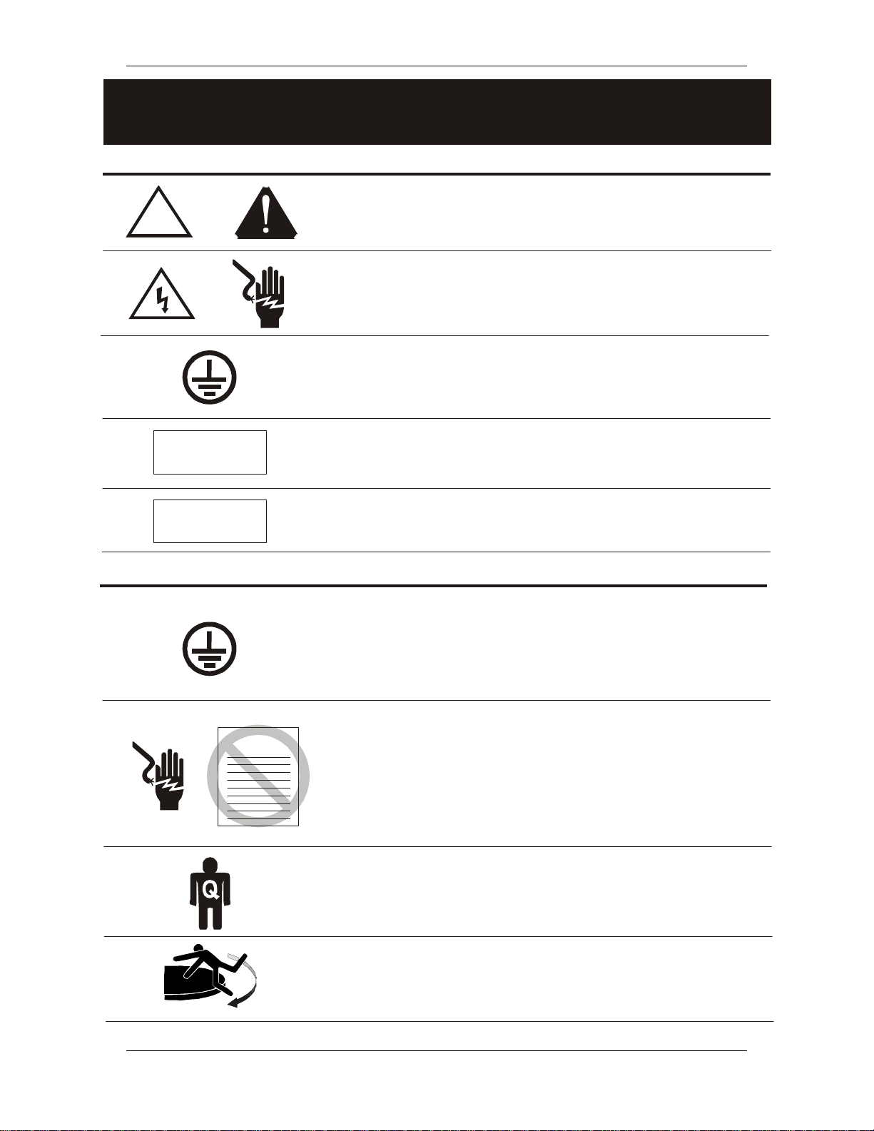
NOTICE: This product and related docume ntation must be reviewed for familiar ization
with safety markings and instructions before operation.
SAFETY SYMBOL DEFINITIONS
!
OR
CAUTION
WARNING
REFER TO MANUAL
instruction manual for additional information.
HIGH VOLTAGE
could result in severe personal injury or death.
PROTECTIVE EARTH GROUND (SAFETY G ROUND)
Indicates protective earth terminal. You should provide uninterruptible safety
ea rth ground from the main power source to th e product input wiring
terminals, power cord, or supplied power cord set.
CAUTION
minor personal i n ju r y and/or propert y damage. I ncluded text giv es proper
procedures.
WARNING
SEVERE pe r sonal inju ry and/or proper ty damage. Included text gives pr o per
procedures.
GENERAL SAFETY CONSIDERATIONS
BEFORE POWER IS APPLIED TO THIS INS TRUMENT,
GROUND IT PROPERLY
cable to a power source provided with protective ea rth contact. Any
interruption of the protective (grounding) conductor, inside or outside the
ins trument, or dis c onnection of the protective ea rth termi nal could result in
personal injury.
When product is marked with this symbol refer to
Indicates presence of hazardous voltage. Unsafe practice
Denotes a hazard. Failure to follow instructions could result in
Denotes a hazard. Failure to follow instructions could result in
through the protective conductor of the A C power
© ETS-LINDGREN L.P. – JANUARY 2003
REV C – PN 399253
WARRANTY
BEFORE SERVICING: CONTACT ETS-LINDGREN -
(or modifying) the unit by yourself may v oid your warranty . I f you attempt to
ser vice the unit by yo urself, disconnect all electrical powe r be fore s t arting.
There ar e v oltages at many points in the instrument which could, if
contacted, cause personal injury. Only trained service personnel should
perform adjust m ents and/or s ervice proce dures upon thi s inst rument.
Capacitors inside this instrument may still be CHARGED even when
instrument is disconn ected from its power source.
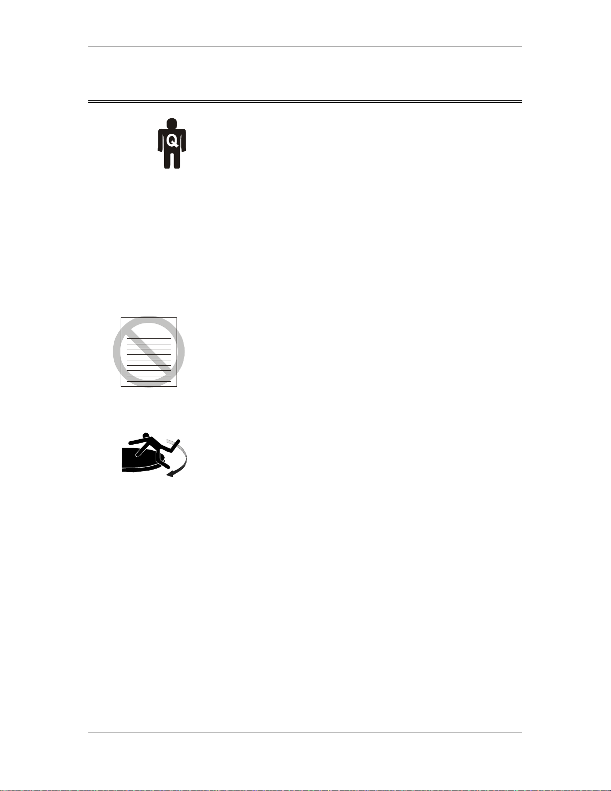
ONLY QUALIFIED PERSONNEL
STAY CLEAR
of moving components during operat i o n of equipment.
shou ld ope rate (or s ervice) this equi pm e nt.
servicing
Page 5

MODEL 2088 ELECTRIC POWERED TURNTABLE Introduction
Archived 3/31/10
INTRODUCTION
The ETS-Lindgren Model 2088 EuroPro™ is an electric-powered
variable-speed turntable platform system designed to be used with
the Model 2090 Positioning Controller for EMI compliance
testing. The Model 2088 is available in three diameters 1.23 meter,
1.53 meter and 2.03 meter. Designed for indoor use, the EuroPro
turntable is perfect for installations in new or existing chambers
where pit excavation is not an option or must be shallow.
The top is conductive with a continuous ground brush to better
electrically couple the turntable to the ground plane. The ground
brushes are attached directly to the top of the table and are in
continuous contact with the floor-flange supplied with the ground
ring option. The brushes point downward from the top of the table.
The drive motor and gearing are located beneath the platform. The
Model 2088 Turntable utilizes a drive sprocket and sprocket drive
with a gear reducer and electric motor. The top of the turntable is
removable to provide easy access in the event that service is
required. The electronics are located in a shielded enclosure.
Signal I/O is via fiber-optic cable.
To prevent over-travel of the turntable in either direction of
movement, “soft” electronic limits can be set using the Model
2090 Positioning Controller. Rotation speed can be varied from the
front panel of the controller or through the IEEE-488 interface bus.
© ETS-LINDGREN L.P. – JANUARY 2003 1
REV C – PN 399253
Page 6

Standard Configuration MODEL 2088 ELECTRIC POWERED TURNTABLE
Archived 3/31/10
STANDARD CONFIGURATION
• Turntable Assembly
• Single-phase electric drive (208-230 VAC 50/60 Hz)
• Variable speed drive
• Conductive top
• Continuous rotation
• Ten meter fiber-optic control cables (standard)
MODEL 2088 OPTIONS
Model 2090 Positioning Controller: This controller provides
control for two separate devices (EMCO towers and turntables) in
any combination, plus the control of four auxiliary devices. The
unit includes a GPIB bus and is compatible with most popular
software. (Firmware revision 3.01 or higher required.)
Ground Plane Interface1: This interface is a square section of
conductive flooring which has a pre-cut opening for the turntable.
As a result, the difficult process of cutting a perfect diameter hole
for the turntable is eliminated. The square edges of the interface
connect to the chamber flooring using framing elements which
provide a uniform and consistent clamping action. A pre-mounted
ground ring is included with the interface. Together with the
EuroPro’s continuous brush system, they provide continuity with
the ground plane.
Shield Room Feed-Through: This option allows the customer to
take the fiber-optic control cable from the control room to the
shield room and still maintain shielding attenuation. The unit is
made of brass for conductivity and provides attenuation of greater
than 100 dB at 10 GHz. A single 22.25 mm (.875") hole is
required to mount this option.
Additional Fiber Optic Cable: Additional lengths of fiber optic
cable may be ordered.
1
European manufactured models include ground plane interface.
2 © ETS-LINDGREN L.P. – JANUARY 2003
REV C – PN 399253
Page 7
MODEL 2088 ELECTRIC POWERED TURNTABLE Precautions
Archived 3/31/10
PRECAUTIONS
Read this manual completely before starting installation. This
equipment should be installed and operated only by qualified
personnel.
The electrical installation of this product should be accomplished
by an individual who is authorized to so do by the appropriate local
authority. The installation should be in compliance with local
electrical safety codes.
Do not attempt to service unless qualified to do so. As with any
electrical equipment, ensure unit electrical power has been
disconnected and secured when performing scheduled maintenance
or adjustments.
WARRANTY
Do not make any modifications to this unit without consulting the
factory directly.
Stay clear of all moving components on this equipment.
Do not operate turntable while someone is physically on the
turntable top.
Do not, at any time, place hands or feet in the vicinity of the drive
pinion on the turntable.
Regularly inspect all equipment and conduct scheduled
maintenance in accordance with the factory recommendations
provided.
Only use replacement parts and fasteners ordered directly from the
factory.
© ETS-LINDGREN L.P. – JANUARY 2003 3
REV C – PN 399253
Page 8

Turntable Installation Considerations MODEL 2088 ELECTRIC POWERED TURNTABLE
Archived 3/31/10
TURNTABLE INSTALLATION
CONSIDERATIONS
Pre-planning is essential for a successful installation. Be sure to
discuss your requirements with your sales representative and
request dimensional drawings prior to construction of your site.
POWER AND SIGNAL LINES
Conduit
Power and signal line paths should be planned in advance. Conduit
should be in place before pouring concrete or installing the ground
plane. Be sure to consider the size of the cable bundle when
selecting conduit diameter.
Electrical Considerations
A qualified and licensed electrical contractor should be used to
install power lines, and the installation should comply with all
applicable regulatory agencies. A dedicated circuit should be used,
with the shortest distance possible between the power source and
the turntable.
Access
An access area underneath the turntable is advisable for large
diameter installations. A service switch should be installed to
deactivate the turntable during service.
4 © ETS-LINDGREN L.P. – JANUARY 2003
REV C – PN 399253
Page 9

MODEL 2088 ELECTRIC POWERED TURNTABLE Installation
Archived 3/31/10
INSTALLATION
The following instructions are for the installation of 1.23 and 1.53
meter EuroPro turntables.
The installation of turntables 2 meters and larger will be performed
by a factory installation specialist or by individuals who have been
authorized by ETS-Lindgren to do such work. Proper installation
of the turntable directly affects performance. The following
installation information is provided to familiarize the user of the
turntable with the installation process.
CAUTION Ensure power is off and secured before proceeding
further.
TOOLS REQUIRED
3/16” allen wrench
5/16” allen wrench
3/8” allen wrenches, qty 3
6 mm. allen wrench
3/8” ratchet wrench
12” crescent wrench
15 mm. 12 point socket for ½” square head screws
7/16” open/box end wrench
½” open/box end wrench
¾” open/box end wrench
0.120 drill bit for 6-32 self tapping screws
“A” & “B” drill for ¼-20 self tapping flat head screws
27/64” drill bit for ½”-13 Tap
3/8” hand drill
½”–13 Tap
#2 phillips screw bit
#3 phillips screw bit
Measuring tape
Pry bar
Level
Square
Hacksaw
Black marker
File
WD 40
© ETS-LINDGREN L.P. – JANUARY 2003 5
REV C – PN 399253
Page 10

Installation MODEL 2088 ELECTRIC POWERED TURNTABLE
Archived 3/31/10
3/4“ pipe clamp ends
3/4“ pipe (length depends on table size 6 ft. will cover most
tables)
1-1/2“ C-clamps, qty 8
Cutting Oil
Syringe for applying conductive grease
Grease Gun
Vacuum
Concrete Pit Installations
1/2“ hammer drill
1/2“ x 12 “ masonry bit
3/16" x 6” masonry bit
1/4" x 1-3/4“ Tapcon Screws or equivalent
1. The turntable installation will vary based on the host location.
There are several installation options presented in some steps,
please select the one that applies to your location.
2. Uncrate all parts. Check all parts for any shipping damage.
Ensure a clear area is available to assemble the turntable unit
safely.
NOTE: Do not discard any packing material until the turntable
is fully assembled.
3. Verify that that fiber optic cable is long enough to reach from
the turntable to the control room. When working around the
table avoid stepping on the fiber optic connectors located at the
relay box.
4. If the turntable is to be installed in a pit, check pit depth and
inside diameter and compare measurements with the drawings,
for your turntable size, at the back of this manual.
The inner diameter of the receptacle pit should be as follows:
1.23 meter turntable = 50.44”
1.53 meter turntable = 62.25”
a. If you have a paneled floor, did not purchase the integrated
ground plate interface option, and are installing the
turntable into a pit in the ground plane a receptacle hole
must be cut in the floor panels.
6 © ETS-LINDGREN L.P. – JANUARY 2003
REV C – PN 399253
Page 11

MODEL 2088 ELECTRIC POWERED TURNTABLE Installation
Archived 3/31/10
b. If you have purchased the Integrated Ground Plate Interface
option. It should be installed prior to lowering the turntable
into place.
5. Remove the bolts which attach the top onto the turntable drive
assembly. Refer to the assembly drawing in the rear of this
manual for more details.
CAUTION Lifting of the turntable assembly using a forklift or
other lifting machinery should be performed by qualified
personnel.
6. Using a forklift or other appropriate lifting device, place the
turntable bottom into position. The relay box with the fiber
optic connectors should point in the direction that the fiber
optic cable will be installed. This will reduce the chance of the
cable being kinked or bent.
7. Position the table as close as possible to the center by
measuring from the bearing to the inner diameter of the raised
floor. To be sure, measure in at least eight places and split the
difference. Once you have found the center and are
comfortable with the measurements, using a marker, mark
around the perimeter of the table base. These marks may be
used for reference if the assembly moves during placement of
the floor shims or anchor plates. Also when positioning,
attempt to make as many anchor holes miss the floor joint
strips, as possible, if the table is being installed on a panel floor
in a chamber.
8. Most 2088 models have floor anchor plates that will need to be
placed under the base unit. The 1.5 and 2.0 meter models also
have an outer ring of floor plates to support additional casters.
There are connector strips that will be placed between the base
unit and the outer plates to ensure proper spacing. Please refer
to the drawings at the back of this manual for proper floor plate
placement. Using a pry bar, carefully lift the table and place
plates under the anchor holes around the edge on the turntable
base. If you are installing your turntable in a welded chamber
with steel pit and steel raised floor please refer to step 12.
© ETS-LINDGREN L.P. – JANUARY 2003 7
REV C – PN 399253
9. Use ½-13 x 5” square head set screws and ½-13 flange nuts to
hold the plates in place. Screw the plates to the floor using
#14x1” #3 square socket flat head screws. Drill 1/8” pilot
Page 12

Installation MODEL 2088 ELECTRIC POWERED TURNTABLE
Archived 3/31/10
holes for these screws and vacuum up shavings so that you
have good contact with the floor. Continue mounting the rest
of the plates.
10. Once all anchor plates are securely mounted, remove the ½-13
x 5” sets screws and then drill 27/64” pilot holes approximately
¾” deep into the paneled floor. Be careful not to penetrate
the bottom skin of the panel. Vacuum out shavings and dust.
Tap holes ½"-13 about ½" deep then install set screws back
into the plate and floor. Do not drive the screws too far.
11. Now place plates at each caster as shown in the drawings at the
back of this manual. Screw plates down as mentioned above
using ½-13 set screws and flange nuts. Once all plates have
been secured to the floor it is time to level the table to the
raised floor.
12. When mounting to a steel pit and steel raised floor you will not
need ¼” anchor/shim plates. You will need a ½-13 tap, 27/64”
drill for tap, ½-13 x 5” square head set screw and flange nuts.
Drill 27/64” dia. holes in the center hole of each group of 3 at
the perimeter of the turntable base. (Model 2081-6x). Tap each
hole as you drill it and then screw in ½-13 x 5” set screws so
that the table does not move as you go around each location.
Proceed with leveling instructions in step 13.
CAUTION: Before leveling make sure all ½-13 flange nuts are
backed off all the way to avoid pulling plates off the floor.
13. Using a leveling instrument, (torpedo laser level or some other
device), raise the table until it is between 1/8” and 3/16” above
the raised floor, this is just a rough finish height. Do not lower
the other leveling screws on the casters until after the floor
flange has been mounted. Once you have one screw secured
on the floor and the table is level, snug up the remaining
leveling screws by the anchor bolts and lock down the flange
nut to hold the table in place while the turntable floor flange is
being mounted.
8 © ETS-LINDGREN L.P. – JANUARY 2003
REV C – PN 399253
Page 13

MODEL 2088 ELECTRIC POWERED TURNTABLE Installation
Archived 3/31/10
RAISED PANEL FLOOR FLANGE
INSTALLATION
The ground ring assembly includes a floor flange which interfaces
with the brush ring located on the perimeter of the turntable. The
floor flange provides constant electrical contact with the ground
plane and is usually installed with the turntable.
Mounting methods vary according to user specifications. Clearance
holes are provided, at evenly spaced intervals, along the outside
perimeter of the ground ring as a means of attaching the ring to a
customer supplied ground plane. These instructions cover
installation for a paneled floor, please see the section on “Rolled
Steel Flange Mounting in Concrete Pit” for further instructions if
that is where your flange will be mounted.
For this step you will need a pipe clamp and three 3/8” allen
wrenches or some other piece of material that is 3/8” diameter.
You will also need a hand drill, 5/32” drill bit, #3 phillips drive bit,
a small square, marker, and ¼”x 1-3/4” phillips flat head,
TAPCON screws, and a hacksaw.
The turntables described in this manual each have two floor flange
pieces. All of the flanges are cut oversize for bending purposes and
the only one that will need to be cut is the last flange installed.
Using a pipe clamp and 3/8” allen wrenches or 3/8” pin, place a
spacer between the turntable and flange starting in three places in
the center or on the flange. Once there is tension on all three
wrenches, drill a 5/32” hole through the counter-sunk holes in the
floor flange. Drill completely through the panel and place screws
into the holes. Continue working around the flange doing 2 or 3
holes at a time.
NOTE: It is very important that this 3/8” gap between turntable
and floor flange be held as close as possible so that the grounding
brushes seat properly. Also make sure that the flange ends are
flush with each other.
© ETS-LINDGREN L.P. – JANUARY 2003 9
REV C – PN 399253
Page 14

Installation MODEL 2088 ELECTRIC POWERED TURNTABLE
Archived 3/31/10
Typically the last flange will be too long. Turn the flange upside
down, butt one end to the other and evenly mark off with the other
end and trim to fit. Do not cut too much off. It is preferable to not
have more than 1/16" gap between the butt joint when finished.
Continue mounting as stated above until all screws have been
installed. Some screws may fall between the floor panel joints.
Try to position the flanges ensuring as few screws hit these points
as possible, and making sure that the first or last hole in the flange
is not too close to one of these joints. Also the top floor joint strips
will need to be trimmed to fit up against the flange.
ROLLED STEEL FLANGE MOUNTING IN
CONCRETE PIT
Mounting to concrete is the same with the exception of the
mounting hardware. You should have ½-13 wedge type concrete
anchors. Instead of the #14 x 1” square socket flat head screws,
you will use 1/4 x 1-3/4. Phillips flat head TAPCON screws.
You will need a ½” hammer drill with a ½” x 12” hammer drill bit
and a 3/16 x 6” hammer drill bit. Instead of the 1/4 x 1-3/4”
tapcons, you will need ¼-20 x 1” phillips flat head thread rolling
screws for mounting the flange to the rolled steel flange. The drill
hole size for ¼-20 x 1” thread rolling screws is .238 - .242 (B or C
drill). You will also want a small vacuum to clean up concrete
dust so that it does not get into the screw threads making them hard
to screw in.
NOTE: When drilling holes, watch out for buried conduit and pit
drain pipes. Also drill ½” hole as deep as you can. Drill 3/16”
holes about 3 to 4 inches deep.
10 © ETS-LINDGREN L.P. – JANUARY 2003
REV C – PN 399253
INSTALLATION OF STAINLESS STEEL WEAR
STRIP
It is very important that the floor around the turntable pit is level
all the way around. If it is not, it will make the installation of the
wear strip very difficult. For this step you will typically need eight
small 1-1/2” C-clamps , 6-32x 3/8” thread rolling screws, a hand
Page 15

MODEL 2088 ELECTRIC POWERED TURNTABLE Installation
Archived 3/31/10
drill, 0.120 dia. drill bits, a #2 phillips bit, and some cutting oil.
Start the strip 1/8" below the surface of the flange at the end with
the hole closest to the end of the strip. Also start with the first 2
holes in strip in between the casters. Place a clamp about 2” on
either side of the hole on the strip in 4 places and then transfer drill
0.120 dia. holes into the aluminum floor flange and then screw in
the 6-32 x 3/8” thread rolling screws.
NOTE: Some of the pre-drilled holes in the strip will be in the path
of a caster. For these holes, casters will need to be removed by
taking out the center axle of the caster. Be careful not to lose any
washers or allow the washers to fall out.
NOTE: Be careful not to bend the stainless steel strip, this will
make it difficult to install properly. Do not let the stainless steel
strip come up above the top of floor flange since it may bend when
something heavy is rolled over it. It may be beneficial to be
slightly below the surface of the flange.
Continue installation around the turntable with the wear strip.
When you get to the end, you will need to cut the strip to length.
Let the strip overlap the fixed end, and using a square, mark a line
even with the fixed end. The gap of the 2 joints should be less than
1/16”. Deburr the cut. You will need to drill the last hole to match
the spacing on the other end of the wear strip.
© ETS-LINDGREN L.P. – JANUARY 2003 11
REV C – PN 399253
GREASING CASTERS & BEARINGS
Using a synthetic grease, grease all casters. Mobil 1 synthetic is
recommended, do not use a lithium grease.
NOTE: Some casters may not have grease fittings. These will be
sealed bearings and will not require grease.
FINAL LEVELING OF TABLE
Lower all ½-13 leveling screws. Once the table is in place with the
floor flange and wear strip mounted, install all remaining screws
for the spacer plates and tighten. Once this is done, place shim
plates in the center of the turntable and insert leveling screws to
Page 16

Installation MODEL 2088 ELECTRIC POWERED TURNTABLE
Archived 3/31/10
support the center. When you are satisfied that the turntable is
level, tighten all lock-nuts accompanying the leveling screws to
lock the height of the turntable into place. Install the remaining top
sections.
12 © ETS-LINDGREN L.P. – JANUARY 2003
REV C – PN 399253
Page 17

MODEL 2088 ELECTRIC POWERED TURNTABLE Electrical Installation
Archived 3/31/10
ELECTRICAL INSTALLATION
CAUTION: Electrical connection should only be performed by a
qualified electrician and subject to local electrical codes.
The Model 2088 is designed to operate using 208-230 VAC singlephase 50 or 60Hz power.
The branch circuit supplying power to the motor base should be
protected from excess current according to local electrical codes.
ETS-Lindgren has provided integral circuit protection in the motor
base assembly.
Check that the conductor size is adequate for the motor load and
the distance from the mains source. Improperly sized conductors
will lead to a high voltage drop in the power conductors and cause
reduced starting torque and premature motor failure.
The motor base assembly is provided with an IEC-320 power inlet
for connecting to the mains. Prior to servicing the turntable or the
turntable motor base, remove the power connection for safety.
Connect the fiber-optic control cable and install the power
connection per local electrical code. Please refer to the Model 2090
Positioning Controller manual for instructions on connecting the
fiber optic cable. After the fiber optic cable is installed secure it
with a wire tie to one of the leveling screws.
In order to feed the fiber optic connectors through the waveguide
in a chamber it may be necessary to remove part of the protective
sheath. The removal of a portion of the sheath will allow the
connectors to fit through the hole without bending or kinking the
fiber optic cable excessively. Find the spot in which you will need
to remove the sheath and mark. A very sharp knife is needed to
make the splice. Being very careful, cut around the outside of the
sheath at each end of the area needing to be cut, cut very lightly so
as to not cut into the fiber cables. You should then be able to bend
the sheath back and forth until you can see the fiber cables.
© ETS-LINDGREN L.P. – JANUARY 2003 13
REV C – PN 399253
Page 18

Electrical Installation MODEL 2088 ELECTRIC POWERED TURNTABLE
Archived 3/31/10
Next you will need to make a cut down the length of sheath area,
being careful not to cut into fiber cable. You should see two
pieces of white string inside the sheath. Find the string and use it
to split the sheath open. Now insert into the waveguide.
14 © ETS-LINDGREN L.P. – JANUARY 2003
REV C – PN 399253
Page 19

MODEL 2088 ELECTRIC POWERED TURNTABLE Operation
Archived 3/31/10
OPERATION
Please refer to the Model 2090 Positioning Controller manual if
you are unfamiliar with the operation of the unit. A 2090 manual is
included with each 2090 shipment and is also available for
download from our website www.ets-lindgren.com .
With the assembly complete the Model 2090 controller will need
to be connected to the unit and power applied to both the motor
base and controller in order to continue. Refer to the electrical
installation section if you have questions about how to connect the
fiber optic cables.
Using the Model 2090 Positioning Controller check the CW and
CCW rotation in both directions by a few degrees. The position in
degrees increases (+) in the CW direction and decreases (-) in
CCW direction.
The turntable is calibrated at the factory to read out 360 degrees (+
or - 1 degree) for one complete revolution. If the table is not within
this accuracy, the unit can be re-calibrated per the instructions in
the “Turntable Encoder Calibration” section.
APPLICATION OF CONDUCTIVE GREASE
Before placing an EUT on the turntable or configuring it for use.
Using the turntable controller, position the table to the 0 degrees
position. Make a straight line from the table to the flange to verify
the encoder count and positioning of table. Then start the table in
scan mode. Using a syringe, squeeze the contents of one tube of
GC Electronics conductive grease into the barrel. While table is
rotating slowly apply grease to the grounding brushes. Apply one
tube per meter size of the diameter of the table. Run table for
approximately 1 hour to validate proper operation and allow
sufficient lubrication of moving parts.
© ETS-LINDGREN L.P. – JANUARY 2003 15
REV C – PN 399253
Page 20

Operation MODEL 2088 ELECTRIC POWERED TURNTABLE
Archived 3/31/10
EDITING MODEL 2090 POSITIONING
CONTROLLER CONFIGURATION
PARAMETERS
To edit a configuration parameter, press the PARAM key to
display the current parameter. Pressing the PARAM key
repeatedly will scroll down through the parameter list, showing
each parameter in turn. While viewing a parameter, the STEP
keys (INC/DEC) may be used to scroll up or down the parameter
list. This reduces the effort necessary to scan through a long
parameter list using the PARAM key. Pressing any of the
LIMIT/POSITION selection keys will return the display to that
selection. Pressing any of the remaining motion keys will return
the display to the current position and execute that motion.
Pressing the PARAM key again will return to the last displayed
parameter in the list, allowing easy transition between parameter
adjustment and device operation.
Once the desired limit, position or parameter is visible in the
display window, pressing INCRM, DECRM, or ENTER will
toggle into edit mode. The lowest adjustable digit will flash on
and off. Pressing the LOCAL key for that device will switch the
flashing digit to the next higher digit. In this way, it is possible to
rapidly adjust any digit of a multi-digit parameter or limit.
SETTING TRAVEL LIMITS
The Model 2088 is not fitted with mechanically actuated or “hard”
limit switches. It is essential that the user properly set the “soft”
limits in the Model 2090 Controller should non-continuous
operation be desired.
To set the counterclockwise rotational limit for the turntable, press
the DOWN/CCW key under LIMIT. The indicator above this key
will light. Set the limit by pressing the INCRM and DECRM keys
under LIMIT until the desired limit is shown on the display. Then,
press the ENTER key. To set the clockwise rotational limit for the
turntable press the UP/CW key under LIMIT. The indicator light
above this key will light. Set the limit by pressing the INCRM and
16 © ETS-LINDGREN L.P. – JANUARY 2003
REV C – PN 399253
Page 21

MODEL 2088 ELECTRIC POWERED TURNTABLE Operation
Archived 3/31/10
DECRM keys under LIMIT until the desired limit is shown on the
display. Press the ENTER key.
WARNING: Ensure the current travel limit settings will not cause
damage to existing cables and equipment located underneath the
turntable.
Should continuous operation be desired, the Model 2090
Controller permits easy configuration to this type of operation
from the front panel or through the IEEE-488 interface bus. Refer
to the Model 2090 Manual for more information.
TURNTABLE ENCODER CALIBRATION
C Refers to the encoder calibration parameter. This setting is used
to convert the encoder count values returned from a motor base
into the corresponding centimeter or degree position reading. For
turntables, this represents the number of encoder counts per
revolution. The setting for the Model 2088 Turntable Series is:
5440
If the given value does not appear to work correctly, the encoder
calibration value can be determined using the following procedure:
1. Set the encoder calibration value to 3600.
2. Insure that the turntable is positioned to allow more than a full
revolution of travel in the clockwise direction and use the
STEP keys to run the turntable clockwise a few degrees to
remove any play in the table.
3. Mark the current location of the turntable against the ground
ring (masking tape works well), and set the current position
reading to 000.0.
4. Using the STEP keys, rotate the turntable clockwise until it is
again aligned with the mark on the ground ring. For best
results, the last motion should always be in the clockwise
direction to insure that any play in the gearing between the
motor and encoder is accounted for.
© ETS-LINDGREN L.P. – JANUARY 2003 17
REV C – PN 399253
Page 22

Operation MODEL 2088 ELECTRIC POWERED TURNTABLE
Archived 3/31/10
5. Record the reading of the display, ignoring the decimal point
(i.e. 360.0 would be 3600). This is the encoder calibration
value.
NOTE: If the value is below 3600, the resolution of the
encoder is low and thus the 2090 will not provide 0.1 degree
resolution, even though the display shows that digit. If the
value has gone past 9999, the encoder has too many counts per
meter and the 2090 can not correct for it. In this case, contact
ETS-Lindgren for assistance.
6. Enter this value for the encoder calibration value and reset the
limits and position information.
7. Test the turntable by moving it a complete revolution and
comparing the alignment marks. It may be necessary to adjust
the encoder calibration value up or down slightly depending on
the result.
NOTE: When scanning between limits, it is not uncommon to
have a small discrepancy between the absolute position of the
table and the display on the 2090 Controller. This is because
reversing the direction of rotation reverses any gear play
between the encoder and the table top, allowing that play to be
visible in the positioning accuracy.
TURNTABLE CALIBRATION EXAMPLE
The table is set at the 0 degree position. A piece of tape is placed
on the edge of the turntable to line up with the edge of the gearbox
cover. The table is stopped when the tape travels exactly 360
degrees around. The display on the 2090 now reads 356.3 degrees
which is recorded.
The table is rotated CCW back to 0. The parameter button is set on
the “C” setting. The “C” digits display 3430. A new “C” setting is
now calculated:
New “C” = (356.3 divided into 360) times 3430 = 3395 (rounded
off)
The decrement the C parameter to 3395 and “ENTER” is pressed.
18 © ETS-LINDGREN L.P. – JANUARY 2003
REV C – PN 399253
Page 23

MODEL 2088 ELECTRIC POWERED TURNTABLE Operation
Archived 3/31/10
Then the “current position” button is pressed to get back to
operation mode.
The table is rotated from 0 to 360 and the mark is now within one
degree of being one full turntable revolution. Calibration is
complete.
SETTING CURRENT POSITION ON 2090
The Model 2088 Turntable is not equipped with mechanically
actuated or “hard” limit switches. The stopped position of the
turntable platform at 0 degrees may drift overtime depending on
usage. The platform can be rotated periodically back to a desired
position and the 2090 current position can be reset to 0.
To check the current position of the turntable on the Model 2090,
press the CURRENT POSITION key under LIMIT. The indicator
above this key will light and the device’s current position will
appear on the display.
To change the current position setting on the Model 2090, press the
CURRENT POSITION button then the INCRM or DECRM
buttons to select the new setting. Press the ENTER button to save
the new setting.
The “soft” travel limits (CW and CCW) on the 2090 will continue
to function and may need to be reset to accommodate the new
current position setting.
NOTE: The current position cannot be changed to a value greater
than the upper limit or less than the lower limit.
© ETS-LINDGREN L.P. – JANUARY 2003 19
REV C – PN 399253
CHANGING ROTATION SPEED
The Model 2088 Turntable is equipped with a variable speed drive.
Firmware Revision 3.01 (or higher) must be installed in the Model
2090 Controller for proper operation of the Model 2088. The
revision level is displayed on the front panel LED display during
startup of the Model 2090 Controller. If the controller does not
Page 24

Operation MODEL 2088 ELECTRIC POWERED TURNTABLE
Archived 3/31/10
have this or a later revision installed, consult the factory for an
upgrade.
To select one of the four speeds, use the POLAR/SPEED button
to toggle through the speed options. It is necessary to set the Model
2090 parameters to configure the controller to properly control the
motor base. Refer to the Model 2090 Manual to the section which
describes setting the parameters.
Specifically, parameter 2 must be set to the value 3 which is for
variable speed control. Parameter C, which calibrates the encoder
counts to the rotation of the turntable, should be set to the value
5440. This will insure that the position display will properly report
the full 360 degrees of travel.
VARIABLE SPEED SETTINGS
The Model 2090 parameters S1-S4 control the variable speed
settings for the turntable. These parameters are the continuous
variable speed settings for each of the four speed selections
described below. Each of these parameters can be set to any value
from 1 to 255, with the resulting turntable speed being roughly an
S/255 fraction of the maximum speed. Note that it is the nature of
variable speed drives that there is a minimum speed at which the
motor will operate. For the Model 2088 this minimum speed
setting will be somewhere between 30-75 and should correspond to
a value of 0.5 RPM or less. Below this setting, the motor will not
be able to cause rotation, but will be active until a Motor Not
Moving error (E002) occurs.
WARNING: Do not operate the turntable in a stalled condition.
Doing so can cause damage to the drive unit and will invalidate
your warranty! Always insure that the minimum speed setting
specified in the S1-S4 parameters is above the minimum value at
which your table will turn under normal load.
20 © ETS-LINDGREN L.P. – JANUARY 2003
REV C – PN 399253
SPEED SELECTION
For the Variable Speed Turntable, the Polarization/Flotation button
provides the ability to cycle between the four preset speeds
described above. For each press of the button, the turntable will
Page 25

MODEL 2088 ELECTRIC POWERED TURNTABLE Operation
Archived 3/31/10
change to the next speed setting. The polarization LEDs will light
to indicate the speed selection in a binary fashion as shown below:
Speed 1: Both off
Speed 2: Top on, bottom off
Speed 3: Top off, bottom on
Speed 4: Both on
Each speed setting has its own individual overshoot compens ation
value to provide proper overshoot correction for each speed
selection.
GPIB COMMANDS
The following GPIB commands have been added or modified:
Sn Select Speed, where n is 1 or 2 for a two speed turntable
and 1-4 for a variable speed turntable.
S? Query speed selection. Returns 1 or 2 for a two speed
turntable and 1-4 for a variable speed turntable.
SSn Set Speed Value, where n is 1-4. This command is valid
only for a variable speed turntable. Valid speed values are from 1
to 255.
Command Usage: SSn <Speed>
Example: Output 708, "SS1 196;"
Query Speed Value, where n is 1-4. This command is
valid only for a variable speed turntable. Returns a speed value
from 1 to 255.
Command Usage: SSn?
Example: Output 708, "SS2?;"
© ETS-LINDGREN L.P. – JANUARY 2003 21
REV C – PN 399253
Page 26

Hand Control Unit
Archived 3/31/10
MODEL 2088 ELECTRIC POWERED TURNTABLE
HAND CONTROL UNIT
To connect the Hand Control Unit (HCU), remove the connector
cap on the motor base. Plug the cable receptacle from the hand
control unit into the electrical enclosure and screw connectors
completely together. The HCU is now ready to operate. Be sure to
coordinate use of the unit with the operator of the Model 2090
Positioning Controller.
CAUTION Do not plug the Hand Control Unit into the motor base
while that device is in operation. Coordinate with the operator of
the Model 2090 Positioning Controller before plugging in, using,
or unplugging the HCU.
To allow the HCU to operate, push the control switch from MAIN
to HAND. When the HCU is selected, the Model 2090 Positioning
Controller is overridden until control is returned from the HCU. If
the Model 2090 Positioning Controller is left on while the HCU is
used, the Model 2090 Device Controller records all changes in
position.
CAUTION Do not push the CW and CCW buttons at the same
time. Be sure that the motor is completely stopped before reversing
direction with the hand control unit.
When you are ready to change to automated testing, toggle the
control switch from HAND to MAIN.
22
REV C – PN 399253
© ETS-LINDGREN L.P. – JANUARY 2003
Page 27

MODEL 2088 ELECTRIC POWERED TURNTABLE Recommended Maintenance
Archived 3/31/10
RECOMMENDED MAINTENANCE
CAUTION: Do not perform maintenance while turntable is
operating. Disconnect the power connection for safety.
Regular maintenance will prolong the serviceable life of your
turntable. Follow this recommended schedule.
EVERY SIX MONTHS
Grease the casters. Use a good quality bearing grease to lubricate
the casters.
Inspect the ground brush for contaminates. Vacuum the brush to
remove unwanted debris. Add a small amount of conductive
lubricant to the brush interface if required.
Inspect the ground brush for wear. A well maintained ground brush
should have a long serviceable life. Should it need to be replaced,
replacement ground brushes for turntables are available in standard
lengths that are straight and not trimmed. They are assembled at
the factory into the predrilled aluminum extrusion that is attached
around the edge of the turntable. During replacement the brush
assembly is clamped in place using a pipe clamp in order to bend
the brushes to conform to the edge of the turntable top. The
replacement brushes have hole spacing that is machined exactly
the same as the original.
© ETS-LINDGREN L.P. – JANUARY 2003 23
REV C – PN 399253
EVERY 12 MONTHS
Lubricate the main bearing race. Use a grease gun with a good
quality bearing grease. The grease fittings are located inside the
race, 90 degrees apart, underneath the top. Three discharges from
the grease gun in each fitting are adequate.
Grease the gear teeth. Apply a good quality grease to the gear
teeth.
Page 28

Specifications MODEL 2088 ELECTRIC POWERED TURNTABLE
Archived 3/31/10
SPECIFICATIONS
ELECTRICAL
Nominal AC Voltage 230 VAC
Input Frequency 50/60 Hz
Phase Single Phase
AMP 2.0
RPM 0.5/2.0 variable
MECHANICAL
Diameter 1.2 meter 1.53 meter 2.03 meter
Height 14.8 cm
(5.8 in)
Distributed
Load Rating*
*Distributed Load Rating is based on load being evenly distributed
to each section. No point loads under 0.37 sq. m (4 sq. ft) should
exceed 500 kg (1100 lb.); and not over 400 kg should be applied
to a 45 degree segment outboard of the casters.
500 kg
(1100 lb)
14.8 cm
(5.8 in)
1000 kg
(2200 lb)
14.8 cm
(5.8 in)
1000 kg
(2200 lb)
24 © ETS-LINDGREN L.P. – JANUARY 2003
REV C – PN 399253
Page 29

MODEL 2088 ELECTRIC POWERED TURNTABLE Warranty Statement
Archived 3/31/10
WARRANTY STATEMENT
ETS-Lindgren L.P., hereinafter referred to as the Seller, warrants that standard EMCO products
are free from defect in materials and workmanship for a period of two (2) years from date of
shipment. Standard EMCO Products include the following:
Antennas, Loops, Horns
GTEM cells, TEM cells, Helmholtz Coils
LISNs, PLISNs, Rejection cavities & Networks
Towers, Turntables, Tripods, & Controllers
Field Probes, Current Probes, Injection Probes
If the Buyer notifies the Seller of a defect within the warranty period, the Seller will, at the Seller’s
option, either repair and/or replace those products that prove to be defective.
There will be no charge for warranty services performed at the location the Seller designates.
The Buyer must, however, prepay inbound shipping costs and any duties or taxes. The Seller will
pay outbound shipping cost for a carrier of the Seller’s choice, exclusive of any duties or taxes. If
the Seller determines that warranty service can only be performed at the Buyer’s location, the
Buyer will not be charged for the Seller’s travel related costs.
This warranty does not apply to:
Normal wear and tear of materials
Consumable items such as fuses, batteries, etc.
Products that have been improperly installed, maintained or used
Products which have been operated outside the specifications
Products which have been modified without authorization
Calibration of products, unless necessitated by defects
THIS WARRANTY IS EXCLUSIVE. NO OTHER WARRANTY, WRITTEN OR ORAL, IS
EXPRESSED OR IMPLIED, INCLUDING BUT NOT LMITED TO, THE IMPLIED WARRANTIES OF
MERCHANTABILITY AND FITNESS FOR A PARTICULAR PURPOSE. THE REMEDIES
PROVIDED BY THIS WARRANTY ARE THE BUYER’S SOLE AND EXCLUSIVE REMEDIES. IN
NO EVENT IS THE SELLER LIABLE FOR ANY DAMAGES WHATSOEVER, INCLUDING BUT
NOT LIMITED TO, DIRECT, INDIRECT, SPECIAL, INCIDENTAL, OR CONSEQUENTIAL
DAMAGES, WHETHER BASED ON CONTRACT, TORT, OR ANY OTHER LEGAL THEORY.
Note: Please contact the Seller’s sales department for a Return Materials Authorization (RMA)
number before shipping equipment to us.
© ETS-LINDGREN L.P. – JANUARY 2003 25
REV C – PN 399253
Page 30

Illustrations MODEL 2088 ELECTRIC POWERED TURNTABLE
Archived 3/31/10
ILLUSTRATIONS
See assembly drawings on following pages.
26 © ETS-LINDGREN L.P. – JANUARY 2003
REV C – PN 399253
Page 31

Archived 3/31/10
Page 32

Archived 3/31/10
Page 33

Archived 3/31/10
Page 34

Archived 3/31/10
Page 35

Archived 3/31/10
Page 36

Archived 3/31/10
Page 37

Archived 3/31/10
Page 38

Archived 3/31/10
Page 39

Archived 3/31/10
Page 40

Archived 3/31/10
Page 41

Archived 3/31/10
Page 42

Archived 3/31/10
 Loading...