

Page 1

Archived 3/18/10
Model 2081
Turntable Series
2081-2.0, 2081-2.5, 2081-3.0,
2081-4.0, 2081-5.0, 2081-6.0
MANUAL
© ETS-LINDGREN L.P. - JANUARY 2003 REV D – PN 399212
Page 2

MODEL 2081 TURNTABLE SERIES
Archived 3/18/10
ETS-Lindgren L.P. reserves the right to make changes to any products herein to improve functioning,
design, or for any other reason. Nothing contained herein shall constitute ETS-Lindgren L.P. assuming any
liability whatsoever arising out of the application or use of any product or circuit described herein. ETSLindgren L.P. does not convey any license under its patent rights or the rights of others.
© Copyright 2003 by ETS-Lindgren L.P. All Rights Reserved.
No part of this document may be copied by any means
without written permission from ETS-Lindgren L.P.
E-MAIL & INTERNET
Support@ets-lindgren.com
http://www.ets-lindgren.com
USA
1301 Arrow Point Dr., Cedar Park, TX 78613
P.O. Box 80589, Austin, TX 78708-0589
Phone 512.531.6400
Fax 512.531.6500
FINLAND
Euroshield OY
Mekaanikontie 1
27510, Eura, Finland
Phone + 358.2.838.3300
Fax + 358.2.865.1233
JAPAN
4-2-6, Kohinata
Bunkyo-ku
Tokyo 112-0006
JAPAN
Phone + 81 3 3813 7100
Fax + 81 3 3813 8068
CHINA
1917-1918 Xue Zhixuan Building
No 16 Xue Qing Road
Haidian District
Beijing Postcode: 100083
CHINA
Phone + 86 010 82755304
Fax + 86 010 82755307
© ETS-LINDGREN L.P. – JANUARY 2003
REV D – PN 399212
Page 3

MODEL 2081 TURNTABLE SERIES
Archived 3/18/10
Table of Contents
INTRODUCTION ........................................................................................................................................ 1
STANDARD CONFIGURATION .............................................................................................................. 2
OPTIONS ...................................................................................................................................................... 3
PRECAUTIONS ........................................................................................................................................... 4
TURNTABLE INSTALLATION CONSIDERATIONS........................................................................... 6
POWER AND SIGNAL LINES ......................................................................................................................... 6
OUTDOOR INSTALLATIONS .......................................................................................................................... 6
INSTALLATION ......................................................................................................................................... 7
GROUND RING INSTALLATION .................................................................................................................... 9
ELECTRICAL INSTALLATION ............................................................................................................ 10
CONNECTING THE MODEL 2090 POSITIONING CONTROLLER..................................................................... 11
OPERATION .............................................................................................................................................. 12
RECOMMENDED PARAMETERS FOR THE MODEL 2090 POSITIONING CONTROLLER ................................... 13
EDITING MODEL 2090 POSITIONING CONTROLLER CONFIGURATION PARAMETERS .................................. 14
TURNTABLE ENCODER CALIBRATION ....................................................................................................... 14
TT CALIBRATION EXAMPLE ...................................................................................................................... 15
SETTING CURRENT POSITION ON 2090 ...................................................................................................... 17
CAUTION: ON RESETTING CURRENT POSITION ON 2090 ........................................................................... 17
CHANGING ROTATION SPEED .................................................................................................................... 18
SETTING TRAVEL LIMITS .......................................................................................................................... 19
ALTIVAR MOTOR BASE CONFIGURATION ................................................................................................. 20
HAND CONTROL UNIT .......................................................................................................................... 21
RECOMMENDED MAINTENANCE ...................................................................................................... 22
EVERY SIX MONTHS.................................................................................................................................. 22
EVERY TWELVE MONTHS .......................................................................................................................... 23
SPECIFICATIONS .................................................................................................................................... 24
ELECTRICAL .............................................................................................................................................. 24
PHYSICAL .................................................................................................................................................. 24
WARRANTY STATEMENT .................................................................................................................... 25
ILLUSTRATIONS ..................................................................................................................................... 26
© ETS-LINDGREN L.P. – JANUARY 2003
REV D – PN 399212
Page 4
MODEL 2081 TURNTABLE SERIES
Archived 3/18/10
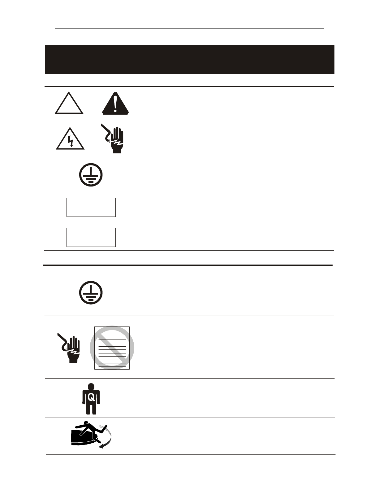
NOTICE: This produc t and related documentation must be r eviewed fo r familiariz ation
with safety markings and instructions before operation.
SAFETY SYMBOL DEFINITIONS
!
OR
CAUTION
WARNING
REFER TO MANUAL
instruction manual for additional information.
HIGH VOLTAGE
could result in severe personal injury or death.
PROTECTIVE EARTH GROU ND (SAF ETY G ROUND)
Indicates protective earth terminal. You should provide uninterruptible safety
ea rth ground from the main power source to the pr o duct input wiring
terminals, power cord, or supplied power cord set.
CAUTION
minor personal i n ju r y and/or propert y damage. Included text gives proper
procedures.
WARNING
SEVERE pe r sonal inju ry and/or proper ty damage. Included text gives pr o per
procedures.
GENERAL SAFETY CONSIDERATIONS
BEFORE POWER IS APPLIED TO THIS INSTRUMENT,
GROUND IT PROPERLY
cable to a power source provided with protective earth contact. Any
interruption of the protective (grounding) conductor , inside or outside the
ins trument, or dis c onnection of the protective ea rth termi nal could result in
personal injury.
When product is marked with this symbol refer to
Indicates presence of hazardous voltage. Unsafe practice
Denotes a hazard. Failure to follow instructions could result in
Denotes a hazard. Failure to follow instructions could result in
through the protective conductor of the AC power
WARRANTY
© ETS-LINDGREN L.P. – JANUARY 2003
REV D – PN 399212
BEFORE SERVICING: CONTACT ETS-LINDGREN -
(or modifying) the unit by yourself may void your warranty. I f you attempt to
ser vice the unit by yo urself, disconnect all electrical powe r befor e starting.
There ar e v oltages at many points in the instrument which could, if
contacted, cause personal injury. Only trained service personnel should
perform adjust m ents and/or s ervice proce dures upon thi s inst rument.
Capacitors inside this instrument may still be CHARGE D even when
instrument is disconn ected from its power source.
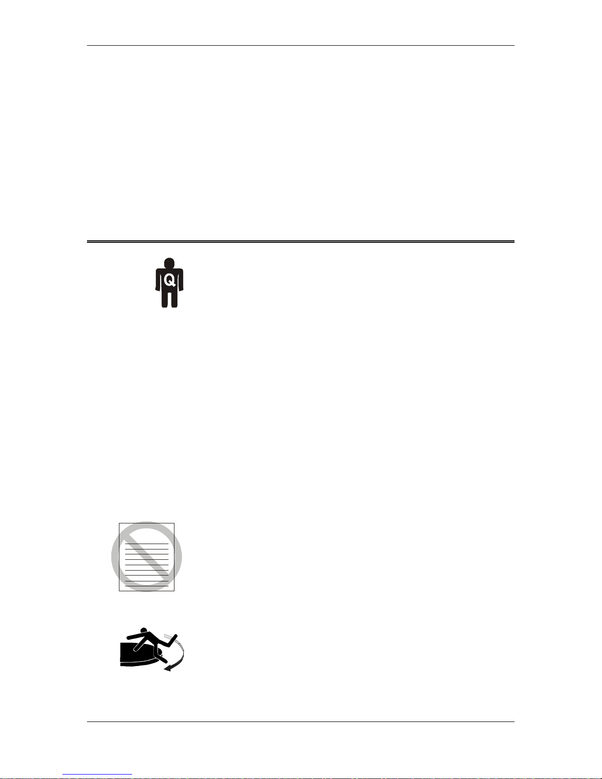
ONLY QUALIFIED PERSONNEL
STAY CLEAR
of moving components during operat i o n of equipment.
shou ld ope rate (or s ervice) this equi pm e nt.
servicing
Page 5

MODEL 2081 TURNTABLE SERIES Introduction
Archived 3/18/10
INTRODUCTION
The ETS-Lindgren Model 2081 is an electric powered turntable
platform system designed to be used with the Model 2090
Positioning Controller for EMI compliance testing. Two meter and
larger tables utilize a pinion and gear drive with a gear reducer and
electric motor. The conductive metal top is outfitted with a
continuous ground brush to electrically couple the turntable to the
ground plane. The drive motor and gearing are located beneath the
platform. The sectional turntable top provides easy access in the
event that service is required. A shielded enclosure contains the
electronics for the system. Signal I/O from the turntable to the
Model 2090 controller is via fiber optic cable.
The bearing on which the turntable rotates has the drive teeth cut
directly on the outside and will easily support most heavily
weighed equipment under test (EUT). Casters underneath the table
surface aid in the support of a cantilevered load. Leveling screws
are located at each caster, between the casters and in the center
section of the assembly for ease in matching height on an uneven
ground plane.
To prevent over-travel of the turntable in either direction of
movement, mechanical limits can be set using dial knobs on the
outside of the encoder enclosure located in the center of the main
pivot bearing. The knobs can be accessed by removing the center
section of the turntable. Soft limits can be set within the
mechanical limits, using the Model 2090 Positioning Controller.
Ground brushes attached directly to the top of the table are in
continual contact with the floor flange supplied with the ground
ring option. The brushes point downward from the top of the table.
To extend the life of the ground brush, a one-piece stainless steel
liner is attached to the inside edge of the stationary floor flange.
© ETS-LINDGREN L.P. – JANUARY 2003 1
REV D – PN 399212
Page 6

Standard Configuration MODEL 2081 TURNTABLE SERIES
Archived 3/18/10
STANDARD CONFIGURATION
• Three-phase electric motor unit (standard)
• Heavy duty two-speed drive system (standard)
• Conductive sectional top
• Convenient rotational limit adjust switches
• Limit override feature
• Ten meter fiber-optic control cables (standard)
• Overall height 400 mm (15.75 in)
• Sectional top for easy service access
• Full supporting leveling screws
2 © ETS-LINDGREN L.P. – JANUARY 2003
REV D – PN 399212
Page 7

MODEL 2081 TURNTABLE SERIES Options
Archived 3/18/10
OPTIONS
Model 2090 Positioning Controller: This controller provides
control for two separate devices (towers and turntables) in any
combination, plus the control of four auxiliary devices via a fiber
optic interface. The unit includes a GPIB connection and is
compatible with most popular EMI measurement software.
Hand Control Unit: This sturdy, hand-held controller will allow
the user to manually operate the table remotely and independently
from the Model 2090 Positioning Controller. This controller
attaches conveniently to the electrical enclosure located on the
base of the turntable. Functions include: Clockwise (CW),
Counterclockwise (CCW) and Hand/Main Control selection.
Slip Ring: This option allows continuous rotation of the turntable
through the use of the latest technology in mercury slip-rings. The
slip ring option is typically supplied with Schuko or NEMA
connectors. Specify part #103441 for NEMA connectors, and part
#103351 for Schuko connectors. The amperage rating for the
standard electrical assembly is 20 amps. Consult the factory for all
custom requirements on slip-rings.
Shield Room Feed-through: This option allows the customer to
take the fiber optic control cable from the control room to the
shield room while maintaining shielding attenuation. The unit is
made of brass for conductivity and provides attenuation of greater
that 100 dB at 10 GHz. A single 22.25 mm (.875 inch) hole is
required to mount this option.
Additional Fiber Optic Cable: Various lengths of fiber optic
cable are available by customer order. The standard length
provided is 10 m (32.8 ft).
Variable Speed Drive: An optional variable speed drive package
is available with the Model 2081 Turntable. Speed adjustment is
electronically controlled by the Model 2090 via the front panel or
through the GPIB interface.
© ETS-LINDGREN L.P. – JANUARY 2003 3
REV D – PN 399212
Page 8
Precautions MODEL 2081 TURNTABLE SERIES
Archived 3/18/10
EUT Power Outlets: Receptacles are usually mounted on the base
of the turntable at its center axis point. These receptacles can be
custom mounted, flush with the tabletop on some turntables.
Consult the factory for more details.
Mounted LISNs: LISNs can be mounted to the underside of some
turntables. This option is only practical on larger turntables with
sufficient clearance.
PRECAUTIONS
Read this manual completely before starting installation. This
equipment should be installed and operated only by qualified
personnel.
Ensure correct voltage setting is selected on the Motor Base unit
(when applicable).
The fiber optic cable must be looped through the “P” clip installed
on the front panel of the motor base. Failure to do so will increase
the chance of the cable being accidentally pulled, thus breaking the
fiber optic connectors.
Do not attempt to service unless qualified to do so. As with any
electrical equipment, ensure unit electrical power has been
disconnected and secured when performing scheduled maintenance
or adjustments.
WARRANTY
Do not make any modifications to this unit without consulting the
factory directly.
Stay clear of all moving components on this equipment.
Do not, at any time, place hands or feet in the vicinity of the drive
pinion on the turntable.
Do not operate the turntable while someone is physically on the
turntable top.
4 © ETS-LINDGREN L.P. – JANUARY 2003
REV D – PN 399212
Page 9

MODEL 2081 TURNTABLE SERIES Precautions
Archived 3/18/10
Regularly inspect the equipment for loose fasteners and wear.
Conduct scheduled maintenance in accordance with the factory
recommendations provided.
Only use replacement parts and fasteners ordered directly from the
factory or specified by ETS-Lindgren.
The access plate(s) above the pinion gear should remain firmly
attached with the screws provided at all times. When the plate is
removed for servicing, the electrical breaker located on the
electrical control enclosure should be in the OFF position.
© ETS-LINDGREN L.P. – JANUARY 2003 5
REV D – PN 399212
Page 10

Turntable Installation Considerations MODEL 2081 TURNTABLE SERIES
Archived 3/18/10
TURNTABLE INSTALLATION
CONSIDERATIONS
Pre-planning is essential for a successful installation. Be sure to
discuss your requirements with your sales representative and
request dimensional drawings prior to construction of your site.
POWER AND SIGNAL LINES
Conduit
Power and signal line paths should be planned in advance. Conduit
should be in place before pouring concrete or installing the ground
plane. Be sure to consider the size of the cable bundle when
selecting conduit diameter.
Electrical Considerations
A qualified and licensed electrical contractor should be used to
install power lines, and the installation should comply with all
applicable regulatory agencies. A dedicated circuit should be used,
with the shortest distance possible between the power source and
the turntable.
Access
An access area underneath the turntable is advisable for large
diameter installations. A service switch should be installed to
deactivate the turntable during service.
OUTDOOR INSTALLATIONS
Drainage
A centerline drain of at least 15cm (6in) must be installed to
provide proper drainage during rain storms, etc.
Cold Climate Conditioning
Oil used in the gear assemblies will congeal at 2
Turntables operated in these temperatures should include a heat
source and/or dehumidifier.
6 © ETS-LINDGREN L.P. – JANUARY 2003
REV D – PN 399212
o
C (28o F).
Page 11

MODEL 2081 TURNTABLE SERIES Installation
Archived 3/18/10
INSTALLATION
The installation of turntables 2 meters and larger will be performed
by a factory installation specialist or by individuals who have been
authorized by ETS-Lindgren to do such work. Proper installation
of the turntable directly affects performance. The following
installation information is provided to familiarize the user of the
turntable with the installation process.
1. Uncrate all parts. NOTE: Do not discard any packing material
until unit is fully assembled. Check all parts for any shipping
damage. Ensure a clear area is available to assemble the
turntable unit safely.
2. After removing three ½-13 flat head screws from the center of
the turntable, install three eye-bolts (provided) for lifting the
turntable center drive section.
3. Attach lifting chains or slings though the eye-bolts.
CAUTION Lifting and placement of turntable center drive unit
into a pit should only be performed by qualified personnel.
4. Safely lift the turntable into the pit using a forklift or other
appropriate lifting device, place the turntable bottom or bearing
support section into position.
5. Remove the drive pinion so the turntable may be rotated
manually.
6. If the turntable is to be installed into a pit or floor cut-out,
center and level the assembly. The drawings at the back of this
manual illustrate the placement of floor plates and leveling
screws that will take place in order to anchor and level the
turntable. Your installation specialist may have to make slight
adjustments to accommodate the conditions at your site. After
installing the floor plates and leveling screws the installer will
level the entire turntable by adjusting all the leveling screws.
CAUTION Ensure power is OFF and secured before proceeding
further.
© ETS-LINDGREN L.P. – JANUARY 2003 7
REV D – PN 399212
Page 12

Installation MODEL 2081 TURNTABLE SERIES
Archived 3/18/10
7. After the turntable is level the installation specialist will tighten
all lock-nuts accompanying the leveling screws to lock the
height of the turntable into place.
8. Anchor the turntable through the anchor holes with the
appropriate bolts (provided).
9. With the electrical breaker still in the OFF position, re-install
the drive pinion.
CAUTION Electrical connection should only be performed by a
qualified electrician and in compliance with all applicable
regulatory agencies.
10. Connect the fiber optic control cable and install the power
connection. The “Electrical Installation” section provides
guidelines for the installation of the electrical connection.
11. Return the breaker in the center of the turntable to the ON
position.
CAUTION Keep all body parts away from the drive pinion when
the turntable in energized.
12. Rotate the turntable using the controller to verify proper
operation.
13. Set the travel limits, if desired, by following the instructions in
the section titled “Setting Travel Limits”.
14. Install the ground ring flange provided around the turntable
with flat head screws (not provided). Install the stainless steel
wear strip and apply conductive grease according to the
“Ground Ring Installation” section.
15. With the key provided, adjust the speed of the turntable while it
is running on the CW or CCW direction until the desired speed
is obtained.
16. Install the top sections of the turntable to complete the
assembly.
8 © ETS-LINDGREN L.P. – JANUARY 2003
REV D – PN 399212
Page 13

MODEL 2081 TURNTABLE SERIES Installation
Archived 3/18/10
GROUND RING INSTALLATION
The ground ring assembly includes a floor flange which interfaces
with the brush ring located on the perimeter of the turntable. The
floor flange provides constant electrical contact with the user’s
ground plane and is usually installed with the turntable.
Mounting methods vary according to user specifications. Clearance
holes are provided along the outside perimeter of the ground ring
as a means of attaching the ring to a customer supplied ground
plane. These mounting holes are provided at evenly spaced
intervals.
1. When attaching the ground ring, first center and level the
turntable assembly into the turntable pit. The cutout diameter in
the floor needs to be per the Dimensional Drawing for the
table.
2. Install the floor flange around the turntable. A gap of 5/16” to
7/16” should be maintained around the turntable. Trim flange
to length by match drilling with floor and installing ¼-20
flathead screws.
3. Install wear strip on inside of floor flange by aligning with top
of turntable flange.
4. Make sure that pre-drilled mounting holes in wear strip are
aligned to 2.54cm (1.00”) from bottom of flange.
5. Trim wear strip to size after ensuring that the full
circumference of the flange is covered by the strip.
6. Using pre-drilled holes on wear strip as a template, drill holes
through the flange.
7. Secure wear strip to floor flange using 6-32 x 3/8” hex head
stainless steel thread cutting screws (furnished with turntable).
8. Apply conductive grease (furnished with turntable) on wear
strip along the brush contact area (approximately 1” to 2” from
the top of the strip).
© ETS-LINDGREN L.P. – JANUARY 2003 9
REV D – PN 399212
Page 14

Electrical Installation MODEL 2081 TURNTABLE SERIES
Archived 3/18/10
ELECTRICAL INSTALLATION
CAUTION It is important that this procedure be performed by a
qualified electrician prior to energizing the unit.
The Model 2081 is designed to operate using either 208-230 VAC
three–phase 60 Hz or 400 VAC three phase 50 Hz power. The
appropriate power requirements are determined when the order is
placed. Other power ratings are available on a special order basis.
1. The branch circuit supplying power to the motor base should
be protected from excess current according to local electrical
codes. ETS-Lindgren has provided a three pole circuit breaker
integral to the relay control enclosure. This circuit breaker also
serves as a service switch and removes motor power from both
the control enclosure assembly and the motor.
WARNING With the circuit breaker in the off position some parts
with AC hazards still present a potentially lethal shock hazard.
2. Check that the conductor size is adequate for the motor load
and the distance from the mains source. Improperly sized
conductors will lead to a high voltage drop in the power
conductors and cause reduced starting torque and premature
motor failure.
3. The motor base assembly is provided with an unterminated
flexible conduit with input power leads exposed. This flexible
conduit is to be terminated into a junction box fitted on or near
the motor base. Terminate the power leads of the motor base
assembly according to local electrical code requirements.
2081 Electrical
Wiring Color
Code
Line Conductors
(3 each)
Neutral N/A Blue
Protective Earth Green with yellow
208-230 VAC
60 Hz 3 phase
Brown Brown
stripe
380-410 VAC
50 Hz 3phase
Green with yellow
stripe
10 © ETS-LINDGREN L.P. – JANUARY 2003
REV D – PN 399212
Page 15

MODEL 2081 TURNTABLE SERIES Electrical Installation
Archived 3/18/10
CONNECTING THE MODEL 2090
POSITIONING CONTROLLER
Any combination of primary devices (towers, turntables,
reverberation paddles, MAPS, etc.) can be connected to the two
Device Interface ports located on the rear panel of the Model 2090
controller. For easy set up of an EMC facility, it is recommended
that the turntable be connected to the Device 2 interface port. The
controllers default settings are for a tower connected to the Device
1 interface port and a turntable connected to the Device 2 port.
Primary device connection is accomplished by way of a dual fiberoptic cable included with the device. This cable terminates into
two ST connectors that are identical at both ends. The cable is
symmetrical; either end can be connected to the controller. A fiber
optic cable that is connect to the IN port of a device should, at the
other end, be connected to the primary OUT port of the motorbase.
A fiber connected to the OUT port of the device should, at the
other end, be connected to the primary IN port of the motorbase.
Older motor base designs have only one fiber optic connector pair,
while the newest motor base interface provides a secondary
interface reserved for future expansion.
NOTE: Fiber optic cabling for each device should not be allowed
to hang unsupported from the rear panel of the controller. The
fibers and connectors are easily broken if twisted or bent. Keep the
fiber optic cables as straight as possible from the connector to the
protective sheath.
Using the Model 2090 Position Controller (or hand controller),
rotate the motor base shaft to verify proper operation. Run the
motorbase down to the lower limit CCW and then back it off from
the lower limit just a bit. This step will help after the turntable is
attached to the motorbase and it is time to set the rotation limits for
the turntable.
CAUTION The soft rotational limits in the Model 2090 controller
must be set. Ensure the travel limit settings will not cause damage
to user installed cables and equipment mounted on the table.
© ETS-LINDGREN L.P. – JANUARY 2003 11
REV D – PN 399212
Page 16

Operation MODEL 2081 TURNTABLE SERIES
Archived 3/18/10
OPERATION
Please refer to the Model 2090 Positioning Controller manual if
you are unfamiliar with the operation of the unit. A manual is
included with each 2090 shipment and is also available for
download from our website.
With the assembly complete, the Model 2090 controller will need
to be connected to the unit and power applied to both the motor
base and controller in order to continue. Refer to the section titled
“Connection the Model 2090 Positioning Controller” if you have
questions about how to connect the fiber optic cables.
Using the Model 2090 Positioning Controller check the CW and
CCW rotation in both directions by a few degrees. The position in
degrees increases (+) in the CW direction and decreases (-) in
CCW direction.
The turntable is calibrated at the factory to read out 360 degrees (+
or - 1 degree) for one complete revolution. If the table is not within
this accuracy, the unit can be re-calibrated per the instructions in
the “Turntable Encoder Calibration” section.
12 © ETS-LINDGREN L.P. – JANUARY 2003
REV D – PN 399212
Page 17

MODEL 2081 TURNTABLE SERIES Operation
Archived 3/18/10
RECOMMENDED PARAMETERS FOR THE
MODEL 2090 POSITIONING
CONTROLLER
DEVICE 2
Parameter Value Description
P1 0 Turntable
P2 2 Standard Turntable
P3 000 Infinite Scan Count
P5 1 Non-continuous rotation
P8 2.5 2.5 Second reverse delay
P9 9 Primary GPIB address 9
b1 000 User options disabled
c 3608 3600 encoder counts per meter
S0 -1 Step speed = run speed
S1 31 Speed 1 ~12.5% of max speed
S2 63 Speed 2 ~25% of max speed
S3 95 Speed 3 ~37.5% of max speed
S4 127 Speed 4 ~50% of max speed
S5 159 Speed 5 ~62.5% of max speed
S6 191 Speed 6 ~75% of max speed
S7 223 Speed 7 ~87.5% of max speed
S8 255 Speed 8 = max speed
Oc On Overshoot compensation enabled
© ETS-LINDGREN L.P. – JANUARY 2003 13
REV D – PN 399212
Page 18

Operation MODEL 2081 TURNTABLE SERIES
Archived 3/18/10
EDITING MODEL 2090 POSITIONING
CONTROLLER CONFIGURATION
PARAMETERS
To edit a configuration parameter, press the PARAM key to
display the current parameter. Pressing the PARAM key
repeatedly will scroll down through the parameter list, showing
each parameter in turn. While viewing a parameter, the STEP
keys (INC/DEC) may be used to scroll up or down the parameter
list. This reduces the effort necessary to scan through a long
parameter list using the PARAM key. Pressing any of the
LIMIT/POSITION selection keys will return the display to that
selection. Pressing any of the remaining motion keys will return
the display to the current position and execute that motion.
Pressing the PARAM key again will return to the last displayed
parameter in the list, allowing easy transition between parameter
adjustment and device operation.
Once the desired limit, position or parameter is visible in the
display window, pressing INCRM, DECRM, or ENTER will
toggle into edit mode. The lowest adjustable digit will flash on
and off. Pressing the LOCAL key for that device will switch the
flashing digit to the next higher digit. In this way, it is possible to
rapidly adjust any digit of a multi-digit parameter or limit.
TURNTABLE ENCODER CALIBRATION
The display symbol C refers to the encoder calibration parameter.
This setting is used to convert the encoder count values returned
from a motor base into the corresponding centimeter or degree
position reading. For turntables, this represents the number of
encoder counts per revolution. The setting for the Model 2081
Turntable Series is: 3608
If the given value does not appear to work correctly, the encoder
calibration value can be determined using the following procedure:
1. Set the encoder calibration value to 3600.
14 © ETS-LINDGREN L.P. – JANUARY 2003
REV D – PN 399212
Page 19

MODEL 2081 TURNTABLE SERIES Operation
Archived 3/18/10
2. Insure that the turntable is positioned to allow more than a full
revolution of travel in the clockwise direction and use the
STEP keys to run the turntable clockwise a few degrees to
remove any play in the table.
3. Mark the current location of the turntable against the ground
ring (masking tape works well), and set the current position
reading to 000.0.
4. Using the STEP keys, rotate the turntable clockwise until it is
again aligned with the mark on the ground ring. For best
results, the last motion should always be in the clockwise
direction to insure that any play in the gearing between the
motor and encoder is accounted for.
5. Record the reading of the display, ignoring the decimal point
(i.e. 360.0 would be 3600). This is the encoder calibration
value. NOTE: If the value is below 3600, the resolution of the
encoder is low and thus the 2090 will not provide 0.1 degree
resolution, even though the display shows that digit. If the
value has gone past 9999, the encoder has too many counts per
meter and the 2090 can not correct for it. In this case, contact
ETS-Lindgren for assistance.
6. Enter this value for the encoder calibration value and reset the
limits and position information.
7. Test the turntable by moving it a complete revolution and
comparing the alignment marks. It may be necessary to adjust
the encoder calibration value up or down slightly depending on
the result. NOTE: When scanning between limits, it is not
uncommon to have a small discrepancy between the absolute
position of the table and the display on the 2090. This is
because reversing the direction of rotation reverses any gear
play between the encoder and the table top, allowing that play
to be visible in the positioning accuracy.
TT CALIBRATION EXAMPLE
The table is set at the 0 degree position. A piece of tape is placed
on the edge of the TT to line up with the edge of the gearbox
cover. The table is stopped when the tape travels exactly 360
© ETS-LINDGREN L.P. – JANUARY 2003 15
REV D – PN 399212
Page 20

Operation MODEL 2081 TURNTABLE SERIES
Archived 3/18/10
degrees around. The display on the 2090 now reads 356.3 degrees
which is recorded.
The table is rotated CCW back to 0. The parameter button is set on
the “C” setting. The “C” digits display 3430. A new “C” setting is
now calculated:
New “C” = (356.3 divided into 360) times 3430 = 3395 (rounded
off)
Decrement the C parameter to 3395 and “ENTER” is pressed.
Then the “current position” button is pressed to get back to
operation mode.
The table is rotated from 0 to 360 and the mark is now within one
degree of being one full TT revolution. Calibration is complete.
16 © ETS-LINDGREN L.P. – JANUARY 2003
REV D – PN 399212
Page 21

MODEL 2081 TURNTABLE SERIES Operation
Archived 3/18/10
SETTING CURRENT POSITION ON 2090
The total travel between the mechanical limits is typically set
between 370 and 400 degrees at the factory. Set the 0 degree
position on the 2090 so that the 2090 moves the table between the
mechanical limits without engaging them in normal operation.
EXAMPLE (CW - clockwise, CCW - counterclockwise)
The table is rotated CCW until it stops at the mechanical limit. The
table current position is then set at 0. Then it is rotated CW until it
stops at the CW mechanical limit switch. The controller now reads
385 degrees which is the full travel between mechanical limits.
The current position on the 2090 is then reset to 360 about 10-15
degrees from the CW mechanical limit. This will keep it from
hitting both mechanical limits when rotating from 0 to 360 during
operation by the 2090.
CAUTION: ON RESETTING CURRENT
POSITION ON 2090
The 0 degree position of the 2090 controller is fixed with respect to
the mechanical limits described in the “Setting Current Position on
2090” section if they are not disabled per the instructions in the
“Setting Travel Limits” section.
Should it become necessary to reset the current position readout of
the Model 2090 Controller. The platform can be rotated
periodically back to a desired position and the 2090 current
position can be reset to 0 only if the mechanical limits are disabled.
The CW and CCW limits on the 2090 will continue to function
with the mechanical limits disabled. If the mechanical limits
remain in operation, the 360 travel on the 2090 will no longer be
between mechanical limits and normal operation will be
interrupted if they are not disabled per the instructions in the
“Setting Travel Limits” section.
© ETS-LINDGREN L.P. – JANUARY 2003 17
REV D – PN 399212
Page 22

Operation MODEL 2081 TURNTABLE SERIES
Archived 3/18/10
CHANGING ROTATION SPEED
The ETS-Lindgren two-speed turntable is designed to shift speeds
at a standstill or during rotation. To change rotational speed,
simply depress the POLAR/SPEED button on the front panel of the
Model 2090 Controller. (Refer to the controller manual for more
information). Changing speed on the turntable is also available
through the IEEE-488 GPIB interface.
The shift from high to low speed as well as from low to high speed
should be a relatively smooth transition. A smooth pole changer is
utilized in the motor control assembly which compensates for
changes in torque when switching speeds. No adjustments are
necessary.
The ETS-Lindgren optional variable speed drive provides smooth
speed adjustment throughout the range of adjustment. A variable
frequency drive provides continuous speed adjustment with high
reliability. Adjustment of the turntable’s speed is facilitated by the
Model 2090 Controller and these operations are discussed in detail
in the Model 2090 Controller manual.
18 © ETS-LINDGREN L.P. – JANUARY 2003
REV D – PN 399212
Page 23

MODEL 2081 TURNTABLE SERIES Operation
Archived 3/18/10
SETTING TRAVEL LIMITS
The mechanical limits of the Model 2081 turntable have been
changed from previous models for user convenience, ease of
operation and safety. These limit adjustments are located outside
the center section of the turntable adjacent to the gearbox. In some
installations, it will be necessary to remove several of the top
sections of the turntable to access the limit switch adjustments.
To increase the amount of travel in either direction turn the knob in
the direction indicated by the positive (+) sign. To decrease the
amount of travel in either direction you must turn the knob in the
minus (-) direction as indicated.
WARNING Ensure the current ravel limit settings will not cause
damage to existing cables and equipment located underneath the
turntable.
You may decide not to use any mechanical limits if you want the
turntable to rotate continuously. To do this, the coupling between
the encoder and threaded shaft must be disengaged. To gain access,
remove the knobs and cover to the encoder. Disengage one side of
the coupling by loosening the set screws that link it to the shaft.
Then slide the coupling ¼ inch on the shaft to disengage the teeth
and retighten the shaft set screws.
CAUTION The limits should be set whether or not the soft limits
present in the controller are used. Failure to do so may cause
damage to occur due to overrun of the table in either direction.
Once limits have been set, return the turntable to its original
position by replacing the top center section removed previously.
© ETS-LINDGREN L.P. – JANUARY 2003 19
REV D – PN 399212
Page 24

Operation MODEL 2081 TURNTABLE SERIES
Archived 3/18/10
ALTIVAR MOTOR BASE CONFIGURATION
The following settings are the defaults for the Altivar motor base
set by ETS-Lindgren:
Altivar
208/230 VAC 60 Hz 400 VAC 50 Hz
Setting
bFr 60 50
ACC
dEC
0.1 0.1
0.1 0.1
LSP 0 0
HSP 75 75
UnS 230 400
FrS 60 60
tFr
90 90
Should you need to change the configuration on the Altivar motor
base supplied with your turntable the Altivar manual is available at
www.SquareD.com.
20 © ETS-LINDGREN L.P. – JANUARY 2003
REV D – PN 399212
Page 25

MODEL 2081 TURNTABLE SERIES Hand Control Unit
Archived 3/18/10
HAND CONTROL UNIT
To connect the Hand Control Unit (HCU), remove the connector
cap on the motor base. Plug the cable receptacle from the hand
control unit into the electrical enclosure and screw connectors
completely together. The HCU is now ready to operate. Be sure to
coordinate use of the unit with the operator of the Model 2090
Positioning Controller.
To allow the HCU to operate, push the control switch from MAIN
to HAND. When the HCU is selected, the Model 2090 Positioning
Controller is overridden until control is returned from the HCU. If
the Model 2090 Positioning Controller is left on while the HCU is
used, all changes in position are recorded by the Model 2090
Device Positioner.
CAUTION Do not plug the hand control unit into the motor base
while that device is operational. Coordinate with the operator of
the Model 2090 Positioning Controller before plugging in, using,
or unplugging. Do not push the CD and CCW buttons at the same
time. Be sure that the motor is completely stopped before reversing
direction with the unit.
When you are ready to change to automated testing, toggle the
control switch from HAND to MAIN.
© ETS-LINDGREN L.P. – JANUARY 2003 21
REV D – PN 399212
Page 26

Recommended Maintenance MODEL 2081 TURNTABLE SERIES
Archived 3/18/10
RECOMMENDED MAINTENANCE
CAUTION Do not perform maintenance while turntable is
operating.
Regular maintenance will prolong the serviceable life of your
turntable. Follow this recommended schedule.
EVERY SIX MONTHS
Adjust the encoder chain. The chain should have no more than 20
mm (1/8”) looseness when flexed to a point halfway between the
two sprockets. Adjust the chain by loosening the two screws
holding the encoder assembly. Move the encoder in or out to the
desired tension.
Lubricate the encoder chain. Use a good quality grease to lubricate
the chain.
Grease the casters. Use a good quality bearing grease to lubricate
the casters.
Check the gearbox for fluid leakage. A slight film that collects is
normal. You should not have puddles of fluid. The gearbox is
lubricated and sealed at the factory. Under normal conditions, it
should not require servicing during its life.
Apply conductive grease on the ground brush along the wear strip
contact area (approximately 1 to 2” from the top of the strip).
Inspect the ground brush for wear. A well maintained ground brush
should have a long serviceable life. Should it need to be replaced,
replacement ground brushes for turntables are available in standard
lengths that are straight and not trimmed. They are assembled at
the factory into the predrilled aluminum extrusion that is attached
around the edge of the turntable. During replacement the brush
assembly is clamped in place using a pipe clamp in order to bend
the brushes to conform to the edge of the turntable top. The
22 © ETS-LINDGREN L.P. – JANUARY 2003
REV D – PN 399212
Page 27

MODEL 2081 TURNTABLE SERIES Recommended Maintenance
Archived 3/18/10
replacement brushes have hole spacing that is machined exactly
the same as the original.
EVERY TWELVE MONTHS
Lubricate the main bearing race. Use a grease gun with a good
quality bearing grease. The grease fittings are located inside the
race, 90 degrees apart, underneath the top. Three discharges from
the grease gun in each fitting are adequate.
Grease the gear teeth with a good quality grease.
© ETS-LINDGREN L.P. – JANUARY 2003 23
REV D – PN 399212
Page 28

Specifications MODEL 2081 TURNTABLE SERIES
Archived 3/18/10
SPECIFICATIONS
ELECTRICAL
Model Drive Speeds RPM Voltage Line
2081-2.0 Series
2081-3.0 Series
2081-4.0 Series
2081-5.0 Series
2081-6.0 Series
Frequency
Dual .5/2.0 208-230 60 8 3
Dual .5/2.0 380 50 5 3
Variable .5/2.0 208-230 60 18 3
Variable .5/2.0 380 50 7 3
Dual .5/2.0 208-230 60 8 3
Dual .5/2.0 380 50 5 3
Variable .5/2.0 208-230 60 18 3
Variable .5/2.0 380 50 7 3
Variable .5/2.0 208-230 50/60 15 Single
Dual .5/2.0 208-230 60 8 3
Dual .5/2.0 380 50 5 3
Variable .5/2.0 208-230 60 18 3
Variable .5/2.0 380 50 7 3
Variable .5/2.0 208-230 50/60 15 Single
Dual .5/2.0 208-230 60 13 3
Dual .5/2.0 380 50 8 3
Variable .5/2.0 208-230 60 20 3
Variable .5/2.0 380 50 14 3
Dual .5/2.0 208-230 60 13 3
Dual .5/2.0 380 50 8 3
Variable .5/2.0 208-230 60 20 3
Variable .5/2.0 380 50 14 3
AMP Phase
PHYSICAL
Model Diameter Nominal Height Distributed Load
Rating*
2081-2.0 Series
2081-3.0 Series
2081-4.0 Series
2081-5.0 Series
2081-6.0 Series
*Distributed Load Rating is based on load being evenly distributed to each section. No point loads under
.37 sq. m (4 sq. ft) should exceed 500kg (1100 lb); and not over 500 kg should be applied to a 45 degree
segment outboard of the casters.
2.0 m
6.56 ft
3.0 m
9.84 ft
4.0 m
13.12 ft
5.0 m
16.40 ft
6.0 m
19.69 ft
40.0 cm
15.75 in
40.0 cm
15.75 in
40.0 cm
15.75 in
40.0 cm
15.75 in
40.0 cm
15.75 in
1,500 kg
3,300 lb
4,000 kg
8,800 lb
6,000 kg
13,200 lb
6,800 kg
15,000 lb
9,000 kg
20,000 lb
24 © ETS-LINDGREN L.P. – JANUARY 2003
REV D – PN 399212
Top Construction
Sectional
Aluminum
Sectional
Aluminum
Sectional
Aluminum
Sectional
Aluminum
Sectional
Aluminum
Page 29

MODEL 2081 TURNTABLE SERIES Warranty Statement
Archived 3/18/10
WARRANTY STATEMENT
ETS-Lindgren L.P., hereinafter referred to as the Seller, warrants that standard EMCO products
are free from defect in materials and workmanship for a period of two (2) years from date of
shipment. Standard EMCO Products include the following:
Antennas, Loops, Horns
GTEM cells, TEM cells, Helmholtz Coils
LISNs, PLISNs, Rejection cavities & Networks
Towers, Turntables, Tripods, & Controllers
Field Probes, Current Probes, Injection Probes
If the Buyer notifies the Seller of a defect within the warranty period, the Seller will, at the Seller’s
option, either repair and/or replace those products that prove to be defective.
There will be no charge for warranty services performed at the location the Seller designates.
The Buyer must, however, prepay inbound shipping costs and any duties or taxes. The Seller will
pay outbound shipping cost for a carrier of the Seller’s choice, exclusive of any duties or taxes. If
the Seller determines that warranty service can only be performed at the Buyer’s location, the
Buyer will not be charged for the Seller’s travel related costs.
This warranty does not apply to:
Normal wear and tear of materials
Consumable items such as fuses, batteries, etc.
Products that have been improperly installed, maintained or used
Products which have been operated outside the specifications
Products which have been modified without authorization
Calibration of products, unless necessitated by defects
THIS WARRANTY IS EXCLUSIVE. NO OTHER WARRANTY, WRITTEN OR ORAL, IS
EXPRESSED OR IMPLIED, INCLUDING BUT NOT LMITED TO, THE IMPLIED WARRANTIES
OF MERCHANTABILITY AND FITNESS FOR A PARTICULAR PURPOSE. THE REMEDIES
PROVIDED BY THIS WARRANTY ARE THE BUYER’S SOLE AND EXCLUSIVE REMEDIES.
IN NO EVENT IS THE SELLER LIABLE FOR ANY DAMAGES WHATSOEVER, INCLUDING
BUT NOT LIMITED TO, DIRECT, INDIRECT, SPECIAL, INCIDENTAL, OR CONSEQUENTIAL
DAMAGES, WHETHER BASED ON CONTRACT, TORT, OR ANY OTHER LEGAL THEORY.
Note: Please contact the Seller’s sales department for a Return Materials Authorization (RMA)
number before shipping equipment to us.
© ETS-LINDGREN L.P. – JANUARY 2003 25
REV D – PN 399212
Page 30

Illustrations MODEL 2081 TURNTABLE SERIES
Archived 3/18/10
ILLUSTRATIONS
26 © ETS-LINDGREN L.P. – JANUARY 2003
REV D – PN 399212
Page 31

MODEL 2081 TURNTABLE SERIES Illustrations
Archived 3/18/10
© ETS-LINDGREN L.P. – JANUARY 2003 27
REV D – PN 399212
Page 32

Illustrations MODEL 2081 TURNTABLE SERIES
Archived 3/18/10
28 © ETS-LINDGREN L.P. – JANUARY 2003
REV D – PN 399212
Page 33

MODEL 2081 TURNTABLE SERIES Illustrations
Archived 3/18/10
© ETS-LINDGREN L.P. – JANUARY 2003 29
REV D – PN 399212
Page 34

Illustrations MODEL 2081 TURNTABLE SERIES
Archived 3/18/10
30 © ETS-LINDGREN L.P. – JANUARY 2003
REV D – PN 399212
Page 35

MODEL 2081 TURNTABLE SERIES Illustrations
Archived 3/18/10
© ETS-LINDGREN L.P. – JANUARY 2003 31
REV D – PN 399212
Page 36

Illustrations MODEL 2081 TURNTABLE SERIES
Archived 3/18/10
32 © ETS-LINDGREN L.P. – JANUARY 2003
REV D – PN 399212
Page 37

MODEL 2081 TURNTABLE SERIES Illustrations
Archived 3/18/10
© ETS-LINDGREN L.P. – JANUARY 2003 33
REV D – PN 399212
Page 38

Illustrations MODEL 2081 TURNTABLE SERIES
Archived 3/18/10
34 © ETS-LINDGREN L.P. – JANUARY 2003
REV D – PN 399212
Page 39

MODEL 2081 TURNTABLE SERIES Illustrations
Archived 3/18/10
© ETS-LINDGREN L.P. – JANUARY 2003 35
REV D – PN 399212
Page 40

Illustrations MODEL 2081 TURNTABLE SERIES
Archived 3/18/10
36 © ETS-LINDGREN L.P. – JANUARY 2003
REV D – PN 399212
Page 41

MODEL 2081 TURNTABLE SERIES Illustrations
Archived 3/18/10
© ETS-LINDGREN L.P. – JANUARY 2003 37
REV D – PN 399212
Page 42

Illustrations MODEL 2081 TURNTABLE SERIES
Archived 3/18/10
38 © ETS-LINDGREN L.P. – JANUARY 2003
REV D – PN 399212
Page 43

MODEL 2081 TURNTABLE SERIES Illustrations
Archived 3/18/10
© ETS-LINDGREN L.P. – JANUARY 2003 39
REV D – PN 399212
Page 44

Illustrations MODEL 2081 TURNTABLE SERIES
Archived 3/18/10
40 © ETS-LINDGREN L.P. – JANUARY 2003
REV D – PN 399212
Page 45

MODEL 2081 TURNTABLE SERIES Illustrations
Archived 3/18/10
© ETS-LINDGREN L.P. – JANUARY 2003 41
REV D – PN 399212
Page 46

Illustrations MODEL 2081 TURNTABLE SERIES
Archived 3/18/10
42 © ETS-LINDGREN L.P. – JANUARY 2003
REV D – PN 399212
Page 47

MODEL 2081 TURNTABLE SERIES Illustrations
Archived 3/18/10
© ETS-LINDGREN L.P. – JANUARY 2003 43
REV D – PN 399212
 Loading...