

ETS SA1-LP User Manual

SA1 Speaker Driver Instructions
The SA1 is a single speaker driver designed to connect to the audio output of DVRs, I/P cam eras
etc, for two way audio applications. Note- the audio input of the SA1 is “line level” (0db).
Speaker Placement
Locate the speaker as close as possible to the area of interest in the space to be monitored. Do
not mount the speaker near air conditioning vents, light fixtures or electrical equip ment. The
speaker should be placed at least 5 feet away from the subject(s) to be addressed. A speaker is
still useable in the range of 15-25 feet but is dependent on the level of background noise in the
area. Experimentation in the environment will determine what distances work best.
SA1 location and power
The SA1 interface box is designed to be located next to a DVR or I/P camera. The SA1 requires a
120VAC power source within 3 feet of its location. If this is not possible in your application, you
can splice in up to 100 feet of 18 awg, 2 conductor cable to extend the distance between the AC
power source and the SA1.
Cable Run
Run a 22 gauge, stranded, two conductor shielded cable between the SA1 ampli f ier and the
speaker. Keep the cable run distance under 1,000 feet (70v mode only) and away from AC power
sources, light fixtures and electrical equipment. See Figure 1 for connection diagram.
SA1 level control
The speaker level can be adjusted to a higher or lower volume. Experiment with the level control
to achieve the desired volume.
70V / 8 Ohm direct switch
If you want to use an 8 Ohm speaker, place this switch in t he 8 Ohm position and limit your
speaker cable run to 250 feet. If your are using a 70V speaker, place the switch in the 70v
position and pick the wattage tap closest to 2 Watts or use an ETS Sound Surveillance speaker.
SA1 audio input.
This input is line level (0db). Connect this to the audio output of your DVR, I/P camera, etc. If the
audio output are screw terminals, cut one end off the supplied patch cable and strip back the
wires. Connect the center conductor to “+” terminal and the shield to the “-“ terminal.
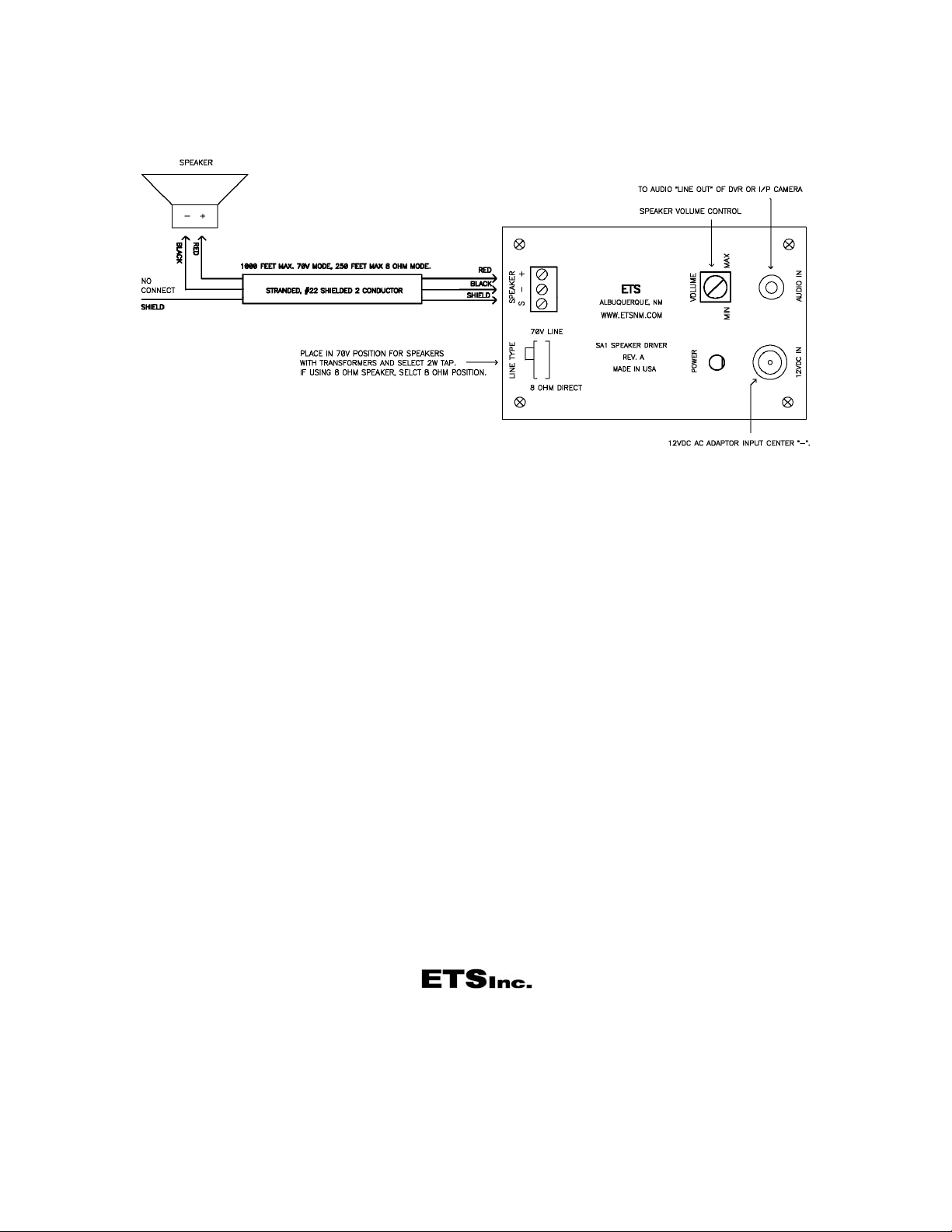
Figure 1.
Caution
It may be against the law to install this microphone kit in certain environments. It may also be against the law
to record conversations of the person(s) being monitored without their knowledge. It is the responsibility of
the installation company and end-user to determine if the application of this product is le gal. These laws vary
from state to state. If you are not informed on these matters, consult a qualified attorney or contact the
appropriate state agency. A sticker is provided with this kit for the applications where notification must be
posted.
Warranty
All ETS products carry a one year parts and labor warranty. This warranty does not cover damages as a
result of misuse, improper handling of the unit or exposure to extreme temperatures or moisture. At its
discretion, ETS reserves the right to repair or replace this unit under the conditions of the warranty. If you
experience problems with your equipment call ETS at: 505-888-3923 to obtain a return authorization
number. Equipment requiring repair beyond the warranty period or units that have been damaged or are not
covered under the warranty can be repaired by ETS for a minimal cost under most conditions.
Made in the USA
by
 Loading...