

Page 1
www.electrotechsytems.com 833-ENV-GURU (833) 368-4878 D00804 Revision B - 20190722
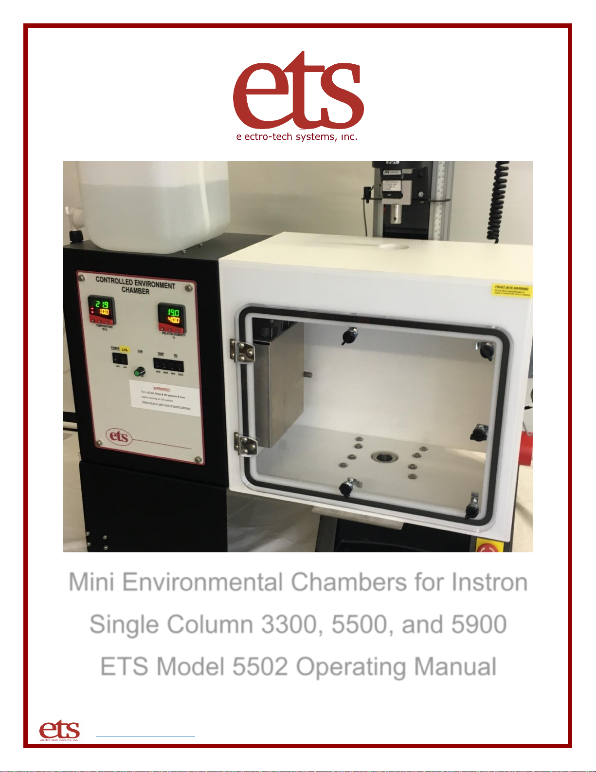
Mini Environmental Chambers for Instron
Single Column 3300, 5500, and 5900
ETS Model 5502 Operating Manual
Page 2

www.electrotechsytems.com 833-ENV-GURU (833) 368-4878 D00804 Revision B – 20190722 - Page 2
Table of Contents
I. Important Safety Information
II. Description of contents
III. Setup Guide
IV. Quick Start Guide
V. Operation Guide
VI. Maintenance/Calibration
VII. Warranty
VIII. Liquid Nitrogen Safety Addendum
IX. Liquid Nitrogen Cooling System Set-Up Addendum
Page 3

www.electrotechsytems.com 833-ENV-GURU (833) 368-4878 D00804 Revision B – 20190722 - Page 3
I. Important Safety Information
SAFETY INSTRUCTIONS
The equipment described in this Manual is designed and manufactured to operate within defined design
limits. Any misuse may result in electric shock or fire. To prevent the equipment from being damaged,
the following rules should be observed for installation, use and maintenance. Read the following
safety instructions before operating the instrument.
POWER
POWER CORD: Use only the power cord specified for this equipment and certified for the country of use. If the
power (mains) plug is replaced, follow the wiring connections specified for the country of use. When installing or
removing the power plug, hold the plug, not the cord.
The power cord provided is equipped with a 3-prong grounded plug (a plug with a third grounding pin). This
is both a safety feature to avoid electrical shock and a requirement for correct equipment operation. If the outlet
to be used does not accommodate the 3-prong plug, either change the outlet or use a grounding adapter.
FUSES: Replace fuses only with those having the required current rating, voltage and specified type such as
normal blow, time delay, etc. DO NOT use makeshift fuses or short the fuse holder. This could cause a shock or
fire hazard or severely damage the instrument.
OPERATION
CAUTION
DO NOT OPERATE WITH COVERS OR PANELS REMOVED. Voltages inside the equipment
consist of line (mains) that can be anywhere from 100-240VAC.
DO NOT OPERATE WITH SUSPECTED EQUIPMENT FAILURES. If any odor or smoke becomes apparent
turn off the equipment and unplug it immediately. Failure to do so may result in electrical shock, fire or permanent
damage to the equipment. Contact the factory for further instructions.
DO NOT OPERATE IN AN EXPLOSIVE ATMOSPHERE: Operating the equipment in the presence of flammable
gases or fumes constitutes a definite safety hazard. For equipment designed to operate in such environments
the proper safety devices must be used such as dry air or inert gas purge, intrinsic safe barriers and/or explosionproof enclosures.
DO NOT IMPEDE THE CHAMBER FROM VENTING EXCESS PRESSURE. The humidification and
dehumidification systems are open loop systems that pump external air into the chamber. If the chamber is not
allowed to vent, pressure could build up and cause serious damage to the chamber.
USE DISTILLED OR DEIONIZED WATER SOURCE FOR HUMIDIFICATION. Build-up of contaminates on the
transducer will cause stress to the transducer and electronics and resulting in premature failure and invalidate
the warranty.
Page 4

www.electrotechsytems.com 833-ENV-GURU (833) 368-4878 D00804 Revision B – 20190722 - Page 4
IF YOUR UNIT INCLUDES OPTIONAL LIQUID NITROGEN COOLING CAPABILITES, REVIEW ALL SAFETY
INFORMATION IN THE LIQUID NITROGEN SAFETY ADDENDUM.
DO NOT USE IN ANY MANNER NOT SPECIFIED OR APPROVED BY THE MANUFACTURER:
Unapproved use may result in damage to the equipment or present an electrical shock or fire
hazard.
Page 5

www.electrotechsytems.com 833-ENV-GURU (833) 368-4878 D00804 Revision B – 20190722 - Page 5
II. Description of Contents
Included:
Item
Qty.
Description
Control Unit
1
Control unit houses the primary control and operating systems to
support heating, cooling, humidification, and dehumidification.
Control Unit Base
1
Base provides support for the control unit and adjustability to align the
control unit with the chamber which will mounted to the Instron unit.
Chamber
1
The Model 5502 includes one chamber as standard. However, chambers are
frequently customized to the application and quantity and size may vary.
Water tank
1
One 2.5-gallon water tank is included as standard. Optionally, the
humidification system can be connected directly to a DI water supply.
Tubing
1
One 10-foot length of tubing is provided to be used for connecting the
water supply, air supply, and water drainage.
Power Cord
1
AC line cord for connecting the control unit to power.
Chamber Support
Bracket and Hardware
1
1 bag containing the vertical support bracket and hardware.
Chamber Base Mounting
Hardware
1
1 bag containing standoffs and hex bolts for mounting chamber to base
of Instron unit.
Cleaning Brush
1
Cleaning brush for preventative maintenance cleaning of the
humidification system ultrasonic transducers.
Optional LN2 cooling:
DC Power Cable
1
Over pressure safety DC power cable
Optional: LN2 cooling:
High pressure hose
1
LN2 High Pressure Hose
Page 6
www.electrotechsytems.com 833-ENV-GURU (833) 368-4878 D00804 Revision B – 20190722 - Page 6
III. Setup Guide
Part 1: Mount the Environmental Chamber onto the Instron unit
Tools Needed:
□ Adjustable wrench
□ 4mm Allen wrench
□ Phillips screwdriver
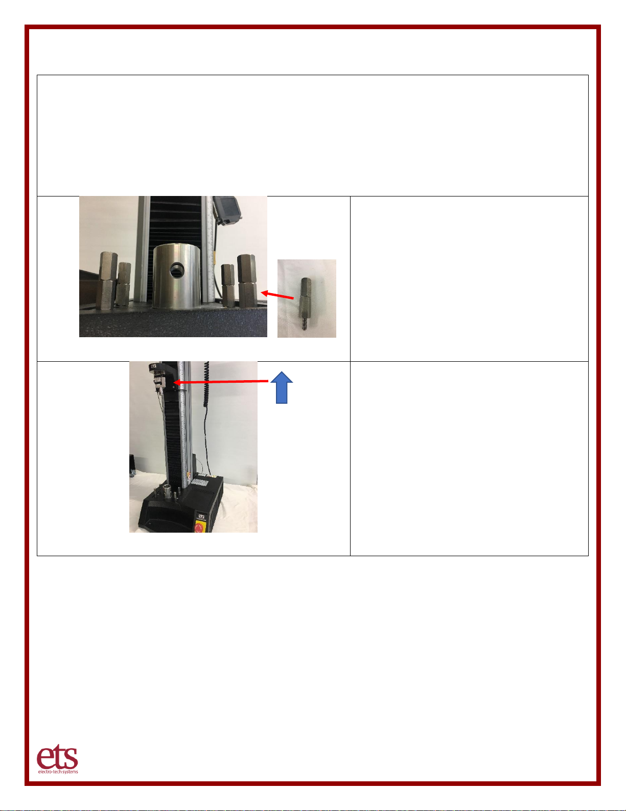
Step 1 – Attach Chamber Standoffs
Insert and tighten the four 2” inch tall standoff
assemblies into the 4 threaded holes in the
Instron platform as shown. An adjustable
wrench can be used to tighten the standoffs.
Step 2 – Raise the Instron armature
Make sure the armature of the Instron unit is
fully raised to ensure it is not in the way of
mounting the environmental chamber.
Page 7
www.electrotechsytems.com 833-ENV-GURU (833) 368-4878 D00804 Revision B – 20190722 - Page 7
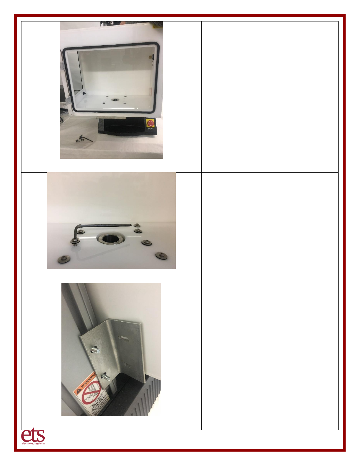
Step 2 – Set the chamber in place
With 2 people, carefully place the chamber
centered from left to right) onto the standoffs
and slide the chamber back into place until
the hex standoffs and center Instron post
align with the holes of the bottom metal
support plate. Once in place, have one
person hold the chamber steady in place,
while the other person completes the next
step of attaching using screws.
Step 3 – Insert and tighten screws
Once the chamber is in place and the
mounting holes are aligned, utilize the four
M6x25mm screws and shock mount washers
(rubber side down) to attach the chamber to
the standoffs. Use a 4mm Allen wrench to
tighten the screws.
Step 4 – Attach rear support bracket
Attach rear support bracket to the Instron
Column utilizing the T-slot nuts.
Start by placing the T-slot nuts into the
channel on the Instron column and let them
fall to the bottom of the channel. Thread the
¼”-20 1-inch studs loosely into the T-slot
nuts. Do not tighten; the t-slot nuts still need
to be able to slide in the channel.
Slide the top stud up and place the bracket
onto the studs with one stud in each of the
slots in the bracket. The bracket should be
oriented with the side having the shorter slots
placed against the column [and the side with
the longer slots placed against the chamber].
Page 8
www.electrotechsytems.com 833-ENV-GURU (833) 368-4878 D00804 Revision B – 20190722 - Page 8
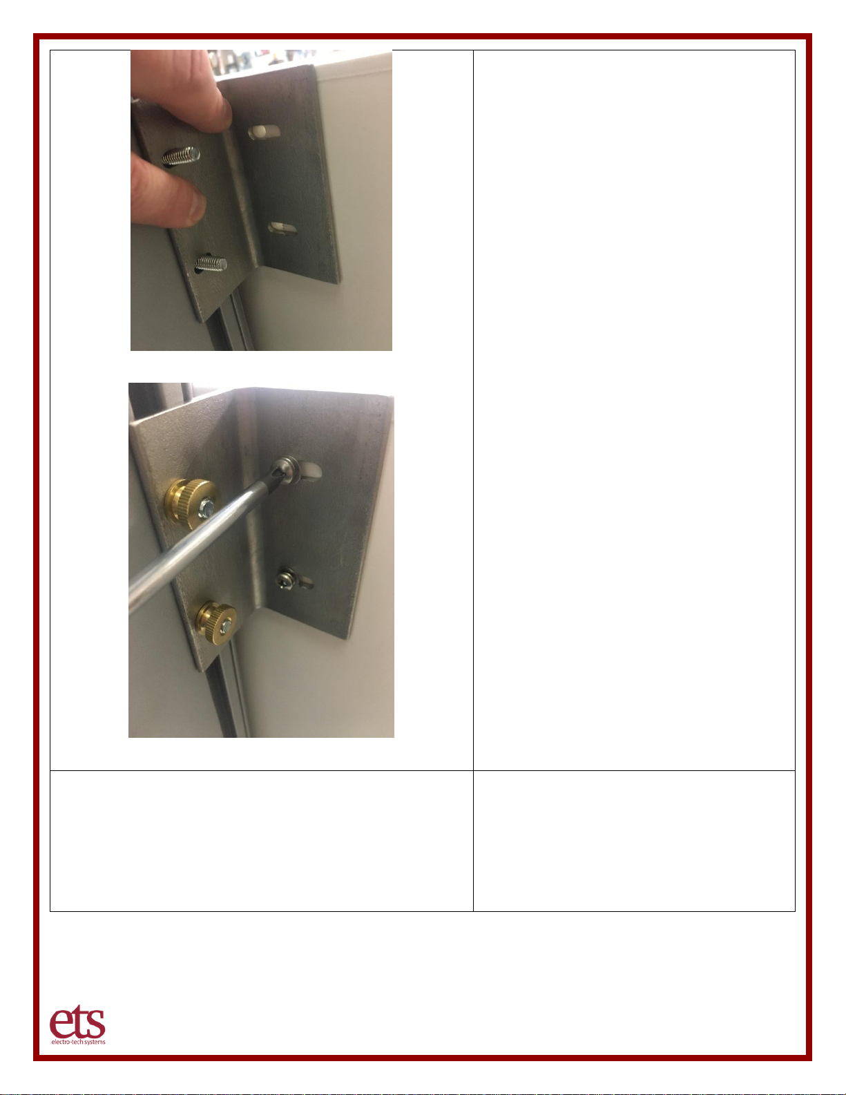
Next, slide the entire bracket upward until the
long slots on the bracket align with the holes
in the chamber. Loosely attach the bracket
to the ETS chamber using the 10-24x3/4”
pan head screws, #10 split washer, and #10
washer. Do not tighten pan head screws.
You can now finger tighten the studs on the
Instron column to lock the T-slot nuts into
place.
Next thread the ¼”-20 thumb nuts loosely
onto the studs on the Instron column. Do not
tighten.
With the bracket in place flush against both
the Instron column and ETS chamber,
proceed to tighten the screws and
thumbnuts. Utilize a Phillips screwdriver to
tighten the 10-24x3/4” pan head screws.
Be careful to avoid placing any strain on the
chamber that could cause stress/cracking. If
necessary, STOP, and loosen the hardware
and readjust the position of the bracket to
eliminate any physical stress and then
tighten.
Refer to documentation from Instron for your
model of single column Instron unit.
Step 5 – Set limits on Instron column
To avoid the Instron unit armature from
destroying the chamber accidently, set your
lower physical stop limit on your Instron
armature to a safe level to avoid physical
contact with the chamber.
Page 9
www.electrotechsytems.com 833-ENV-GURU (833) 368-4878 D00804 Revision B – 20190722 - Page 9
Part 2: Place the Control Unit on the Base and attach to the Chamber
Tools Needed:
□ 3/16” Allen wrench
□ Adjustable wrench
□ Ruler or tape measure
□ Phillips screwdriver
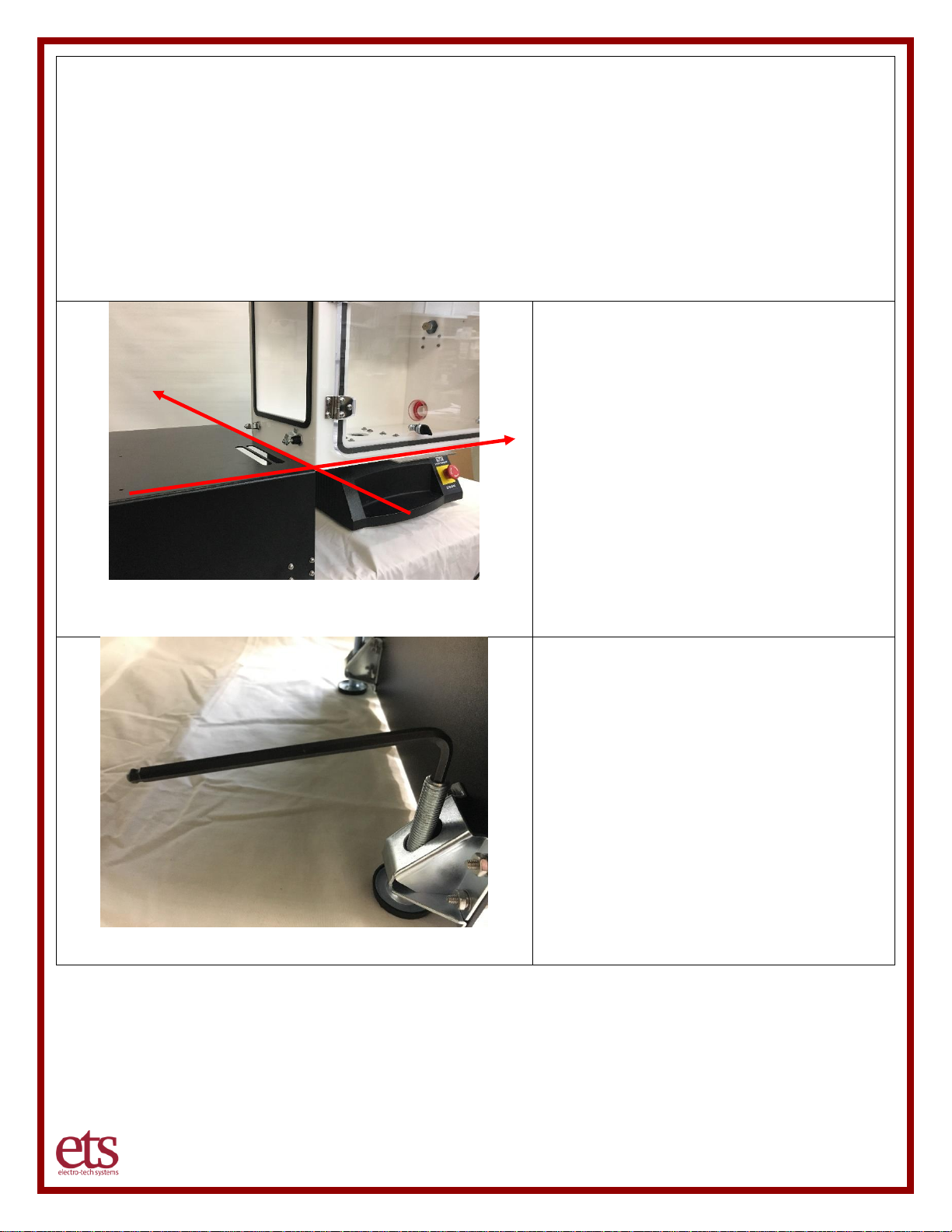
Step 1 – Place the base in position
Set the control unit base on the work surface
to the left of the Instron unit with the front of
the base [the long vent slots in the top of the
base should be to the front].
The front face of the base should be aligned
approximately with the front edge of the
chamber steel support plate and the right
edge of the base should align with the left
edge of the chamber. Ensure the feet of the
base are fully and securely on the work
surface. If necessary, adjust the position of
the Instron unit to allow the proper positioning
of the base.
Step 2 – Adjust the height of the base
Adjust the 4 feet on the bottom of the base
such that the top of the base is level with the
bottom of the chamber. Rotate the feet
clockwise (raise) or counterclockwise (lower)
as needed. You can turn the feet with your
fingers or utilize a 3/16” Allen wrench.
Page 10
www.electrotechsytems.com 833-ENV-GURU (833) 368-4878 D00804 Revision B – 20190722 - Page 10
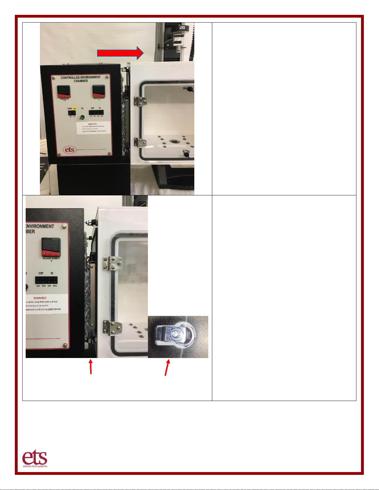
Step 3 – Place the control unit on the base
The control unit should be positioned on the
front half of the base with the front of the
control unit approximately aligned with front
of the base. Set the control unit on the left 3/4
of the base. Initially, about 1/3 of the control
unit may be overhanging the base.
Once placed on the base, gently slide the
control unit towards the opening in the
chamber. As the control unit is placed into
position, the heating/cooling unit extending
from the right side of the control unit should
be inserted through the large opening on the
left side of the chamber. If ANY physical
blockage/resistance occurs, STOP and
carefully adjust the positioning of the control
chamber front to back or raise/lower the feet
on the base to better align the control unit
vertically with the chamber.
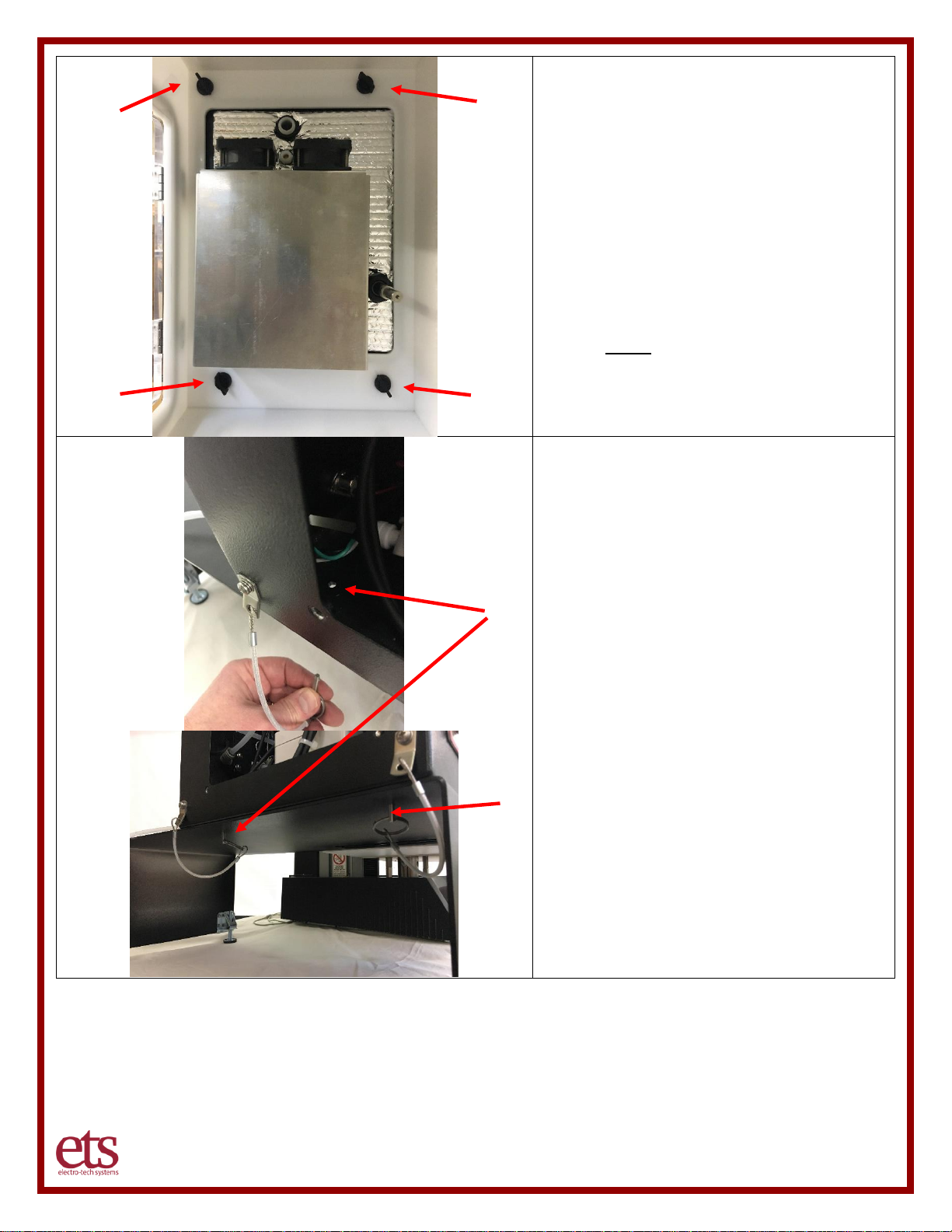
Step 4 – Fine tune position to latch
The final height of the base, positioning of the
control unit from front to back, and levelness
from left to right will all need to be adjusted
until the 4 keyhole slots on the right side of
the control unit align with the 4 latches on the
chamber. In addition, ensure the gap
between the chamber and the control unit is
even from top to bottom.
Adjust the feet on the base and shift the
position of the control unit as appropriate.
Once the gap is even and the latches are
properly aligned, push the control unit flush
with the chamber. If you note any
obstruction, make final adjustments as
needed to eliminate the obstruction.
NOTE: The access panel on the left side of
the control unit can be removed to better
view the alignment of the latches from inside
the control unit.
Even gap top to
bottom
Latch aligned with slot
(Viewed from inside control unit)
Page 11
www.electrotechsytems.com 833-ENV-GURU (833) 368-4878 D00804 Revision B – 20190722 - Page 11
Step 5 – Close the latches
To complete the attachment of the control
unit to the chamber and provide a tight seal,
turn each of the latches clockwise from inside
the chamber. If any significant resistance is
encountered, do not force the latch. Any
significant resistance may indicate
misalignment of the latch mechanism with the
slot; revisit step 4. If the latches are difficult to
reach by hand, use a pair of needle nose
pliers to gently turn the latches.
Step 6 – Insert retainer pins
(recommended)
The system includes two safety locater pins
which connect the base to the control unit.
These locator pins help ensure the control
unit remains properly located on the base.
The base may need to be shifted around
underneath the control unit to align the holes
in the base and control unit.
Once the holes are aligned, insert the two
locator pins.
Page 12
www.electrotechsytems.com 833-ENV-GURU (833) 368-4878 D00804 Revision B – 20190722 - Page 12
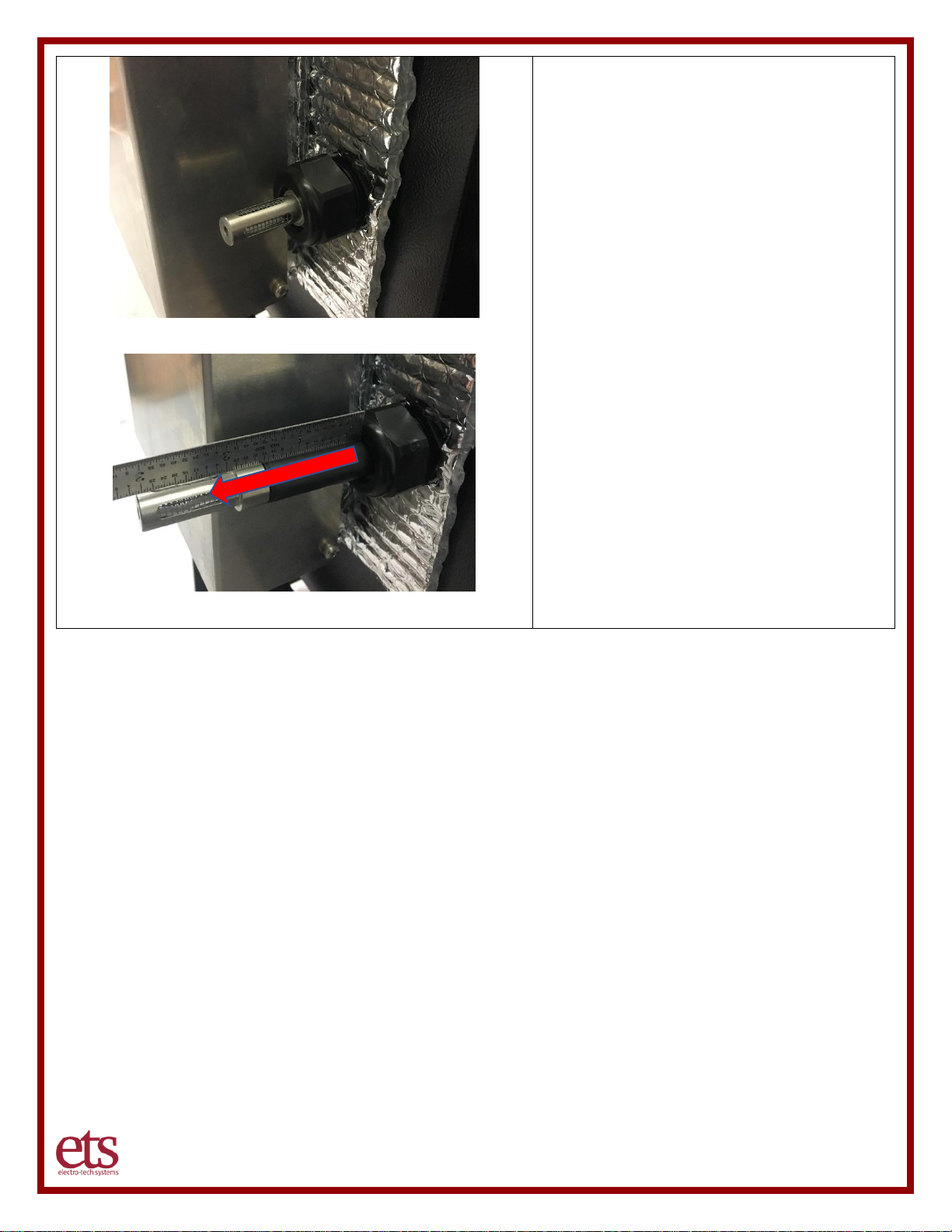
Step 7 – Plug in the control unit sensor
The temperature/humidity sensor separate
from the chamber. Loosen the nut on the
fitting (by hand or with an adjustable wrench)
and push the sensor into the chamber.
Retighten the nut.
Page 13
www.electrotechsytems.com 833-ENV-GURU (833) 368-4878 D00804 Revision B – 20190722 - Page 13
Part 3: Connect all Operating Systems
Tools Needed:
□ Scissors (to cut ¼” tubing to length)
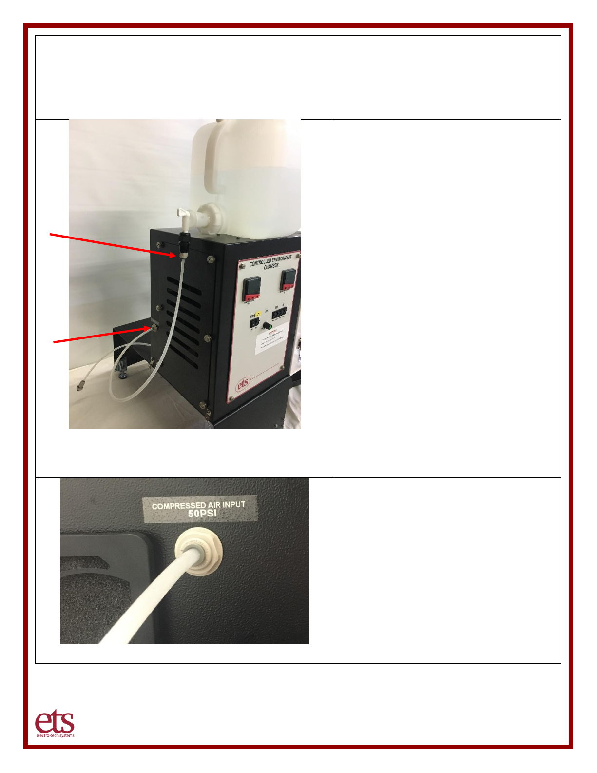
Step 1 – Connect the DI Water Supply
¼” tubing and a 2.5-gallon water tank have
been provided to provide a water supply to
the ultrasonic humidifier.
Fill the water tank with at least 1 gallon of
water and place the water tank on top of the
control unit. Loosen or entirely remove the
air release cap on top of the water tank to
allow water to flow.
Use approximately 2 feet of hose (use
scissors to cut to length) to connect the water
tank to the water intake. Insert one end of
the hose into the quick connect on the water
tank and insert the other end into the water
intake on the control unit.
As an alternative, the unit can be connected
directly to a laboratory deionized (DI) water
supply. Utilize the length of hose necessary
to connect directly to the DI water supply.
IMPORTANT NOTES:
Water will not properly flow out of the water
tank if you do not loosen or remove the air
release cap.
Step 2 – Connect the Air Supply
The Model 5502 utilizes a self-regenerating
dehumidification system that is powered by
air pressure. The system requires
approximately 50 psi of air pressure which
can be provided by a self-contained portable
compressor or house air. Utilize the length of
¼” OD tubing that is long enough to make the
connection to the air system being utilized.
To connect the tubing to the rear of the
control unit, push the tube into the fitting
orifice as far as possible.
Page 14
www.electrotechsytems.com 833-ENV-GURU (833) 368-4878 D00804 Revision B – 20190722 - Page 14
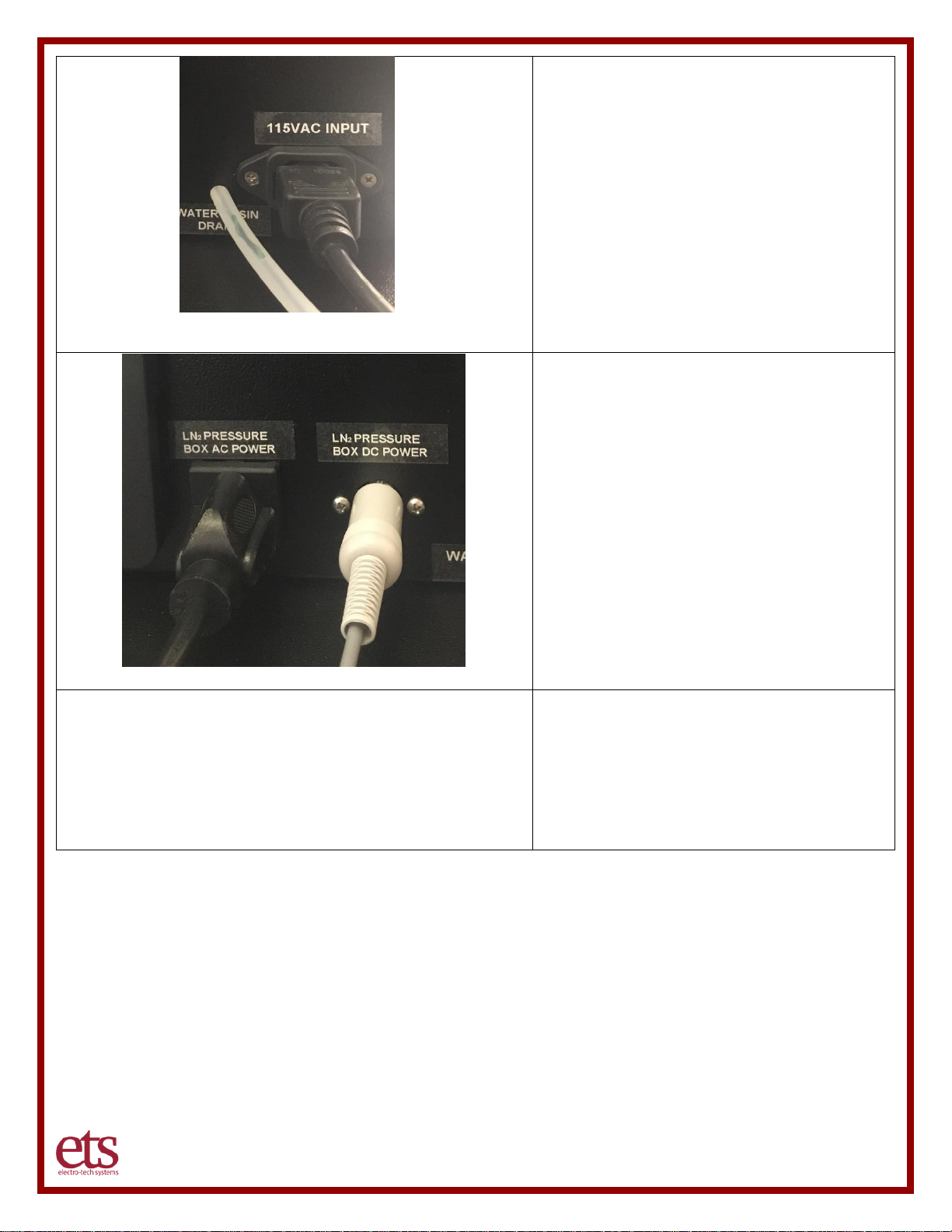
Step 3 – Connect Main Power
Connect the power line cord to the rear
power 115VAC Input plug on the back of the
control unit.
IMPORTANT NOTES:
Since the unit utilizes a water supply, avoid
connecting power if there is a water spill or
your hands are wet.
Step 4 – Optional LN2 Cooling System
Connect the optional LN2 cooling system
power cables as follows:
• Attach the black power cord coming from
the black pressure box attached to the
right side of the chamber to the LN2
Pressure Box AC Box plug on the back of
the control unit.
• Connect the LN2 pressure box DC power
cord to the pressure box DC power jack
and then connect to the LN2 Pressure
Box DC Power connection on the back of
the control unit.
Step 5 – Connecting to LN2 Supply
• See supplemental addendum.
WARNING:
• Exercise extreme caution in
connecting Liquid Cooled Nitrogen.
Page 15
www.electrotechsytems.com 833-ENV-GURU (833) 368-4878 D00804 Revision B – 20190722 - Page 15
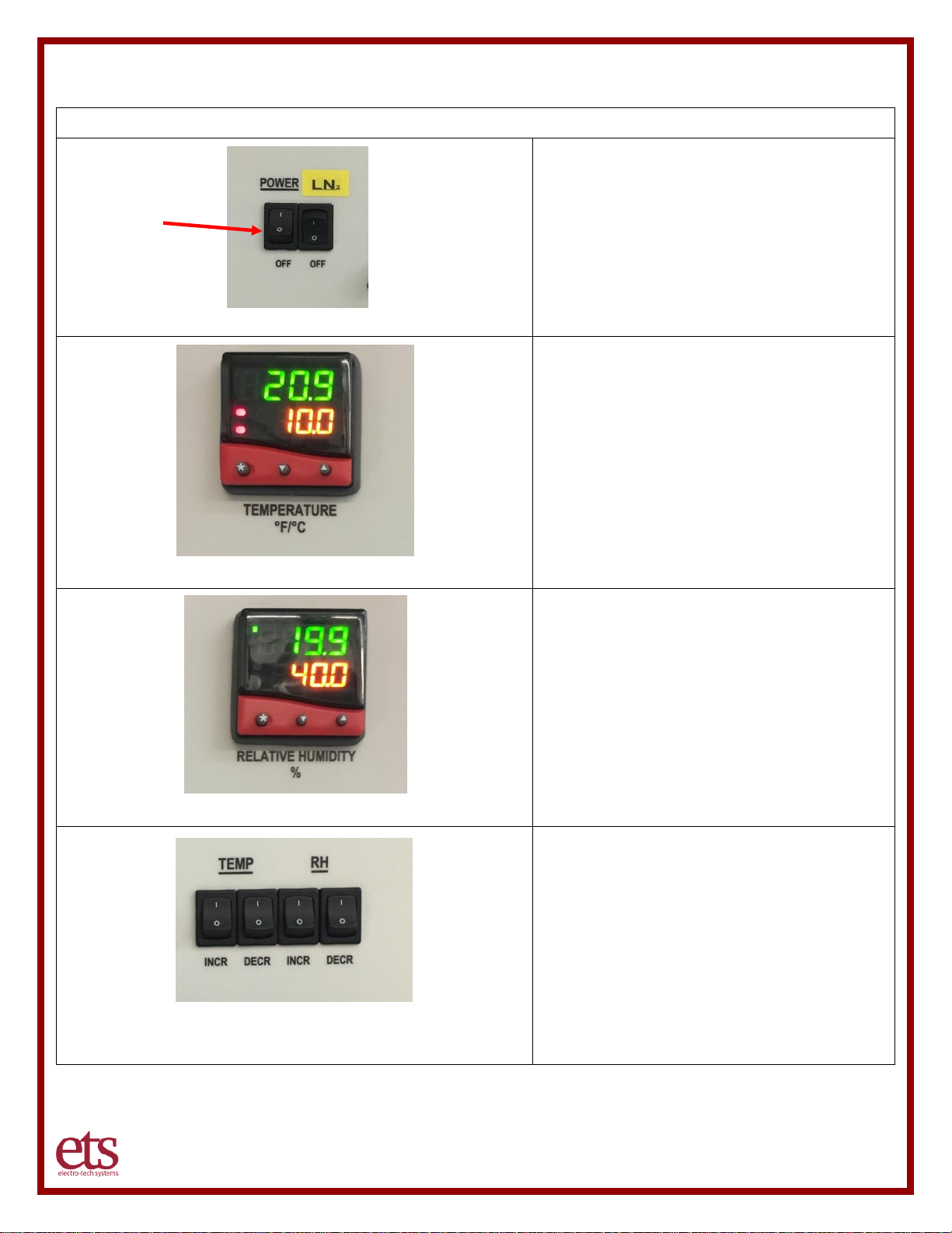
IV. Quick Start Guide
Quick Start Guide
Step 1 – Turn on Power
Turn on Power (I = on). Do NOT turn on LN2
power.
Step 2 – Set Temperature
Set your set point by pressing and
holding the * key and using
increase/decrease buttons to adjust to
your desired temperature.
Step 3 – Set Humidity
Set your set point by pressing and
holding the * key and using
increase/decrease buttons to adjust to
your desired temperature.
Step 4 – Turn on Operating Systems
Flip all four operating system switches to
the on position (I = on). If operating at
edge conditions (<30% RH, >80% RH,
<15C, >35C) only the corresponding
systems need to be used (ex: 20%RH
45C only needs Temp Incr and RH Decr).
Page 16

www.electrotechsytems.com 833-ENV-GURU (833) 368-4878 D00804 Revision B – 20190722 - Page 16
IMPORTANT!
REVIEW ALL SAFETY PRECAUTIONS
AND INSTRUCTIONS
o Liquid Nitrogen Safety Addendum
o Liquid Nitrogen Cooling System Set-Up
Addendum
Step 5 – Optional LN2 System
If the LN2 cooling system is going to be
used, it is IMPORTANT to turn off all of
the other temperature and humidity
systems (reverse Steps 2 and 4 – Turn
OFF the fan and turn OFF all 4 operating
system switches).
See LN2 Addendum for safety
precautions and instructions on setting up
the LN2 system.
Page 17
www.electrotechsytems.com 833-ENV-GURU (833) 368-4878 D00804 Revision B – 20190722 - Page 17
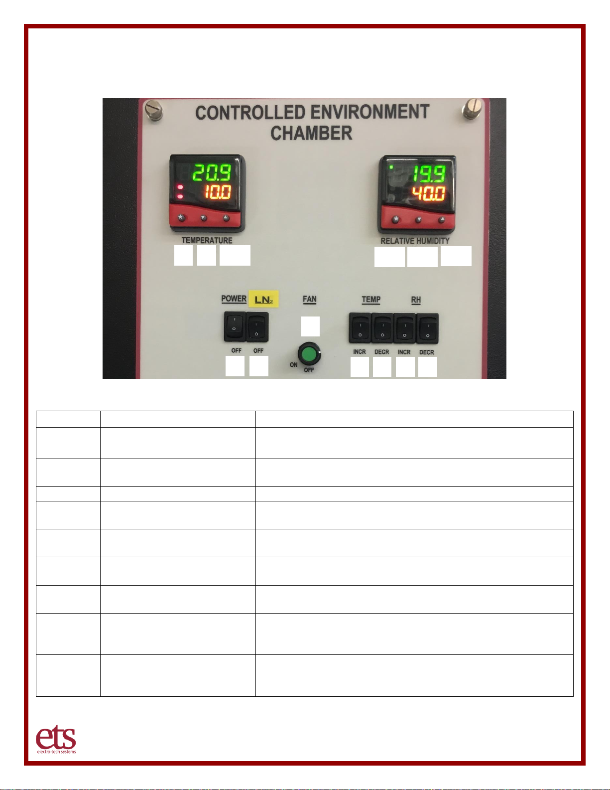
IV. Operation Guide
Control Panel
Button
Description
Functionality
1
POWER
This switch disconnects all power going to the Chamber
Systems. “I” is “ON”, “O” is “OFF”.
2
LN2 (optional)
Turns on power to the liquid nitrogen (LN2) cooling
system (if installed).
3
FAN
No longer used
4
TEMP - INCR
Allows the user to manually disable the Temperature
Heating System. Pushing this switch to the (‘0’) is “Off”
5
TEMP - DECR
Allows the user to manually disable the Temperature
Cooling System. Pushing this switch to the (‘0’) is “Off”
6
RH - INCR
Allows the user to manually disable the Humidification
System. Pushing this switch to the (‘0’) is “Off”
7
RH - DECR
Allows the user to manually disable the Dehumidification
System. Pushing this switch to the (‘0’) is “Off”
8, 9, 10
TEMPERATURE
CONTROLLER
The temperature controller includes a * button along with
down and up arrows to allow selecting and changing
settings.
11, 12, 13
HUMIDITY CONTROLLER
The humidity controller includes a * button along with
down and up arrows to allow selecting and changing
settings.
1
2
3
4 5 6
7
8
9
10
11
12
13
Page 18

www.electrotechsytems.com 833-ENV-GURU (833) 368-4878 D00804 Revision B – 20190722 - Page 18
VI. Maintenance and Calibration
Calibration
For consistency of performance Annual manufacturer conducted calibration is required.
ETS recommends the Model 5502 system be calibrated annually. Only the control unit needs to be
returned for calibration. Be sure to drain the water out of the humidification system prior to returning.
Do NOT return the chamber or the control unit support base.
To return equipment to ETS for calibration or repair it is first necessary to obtain a RMA number, please
call 215-887-2196 or email [email protected]
Page 19
www.electrotechsytems.com 833-ENV-GURU (833) 368-4878 D00804 Revision B – 20190722 - Page 19
Preventive Maintenance
Humidification System
The humidification system utilizes an ultrasonic transducer that has an estimated lifespan of 3000 hours
after which it may need to be replaced. The ultrasonic transducer is not user replaceable. Please
contact ETS for assistance with repair/replacement. To maximize the life of the transducer, utilize an
appropriate water supply (deionized water or distilled water) and perform regular preventative
maintenance after every 300 hours of operational use.
Humidification System Maintenance
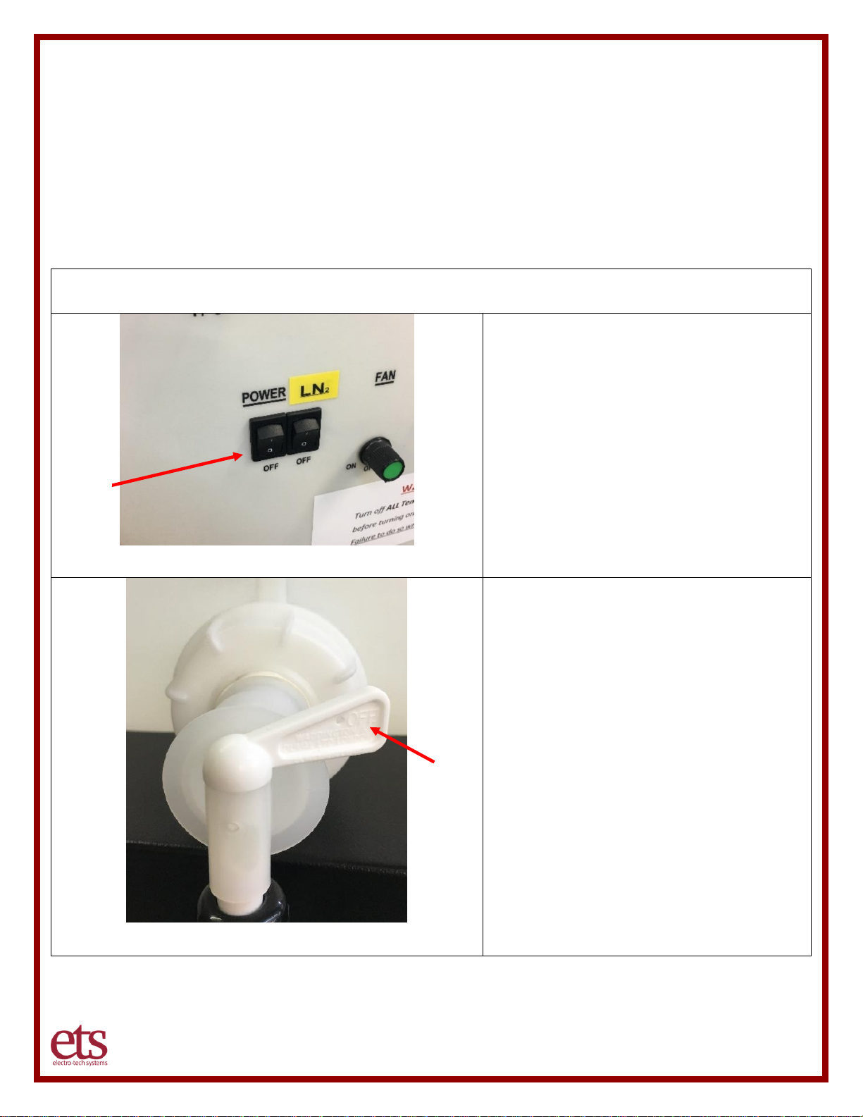
Step 1 – Turn off power and unplug
Turn off the power switch on the control
panel AND unplug the Control Unit power
cord before cleaning the humidifier to avoid
any possibility of electrical shock.
Step 2 – Turn off water supply
Turn off the water source. If utilizing the
2.5-gallon water tank, turn the valve
position to OFF.
OFF
OFF
Page 20
www.electrotechsytems.com 833-ENV-GURU (833) 368-4878 D00804 Revision B – 20190722 - Page 20
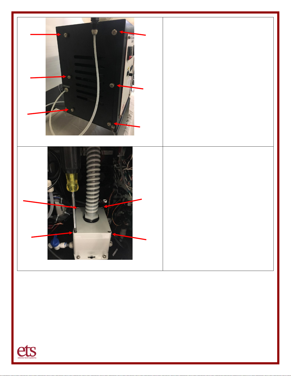
Step 3 – Remove side panel
Remove the side access panel on the
control unit by loosening the 6 large
thumbscrews and set the cover aside.
Be careful to hold the cover with one hand
while loosening the last two screws with
your other hand, to avoid losing control of
the cover and having it fall off in an
uncontrolled manner.
Step 4 – Remove the humidifier cover
Once the side access panel has been
removed, next remove the humidifier top
cover by loosening the 4 screws in the
cover using a Philips screwdriver.
Page 21
www.electrotechsytems.com 833-ENV-GURU (833) 368-4878 D00804 Revision B – 20190722 - Page 21
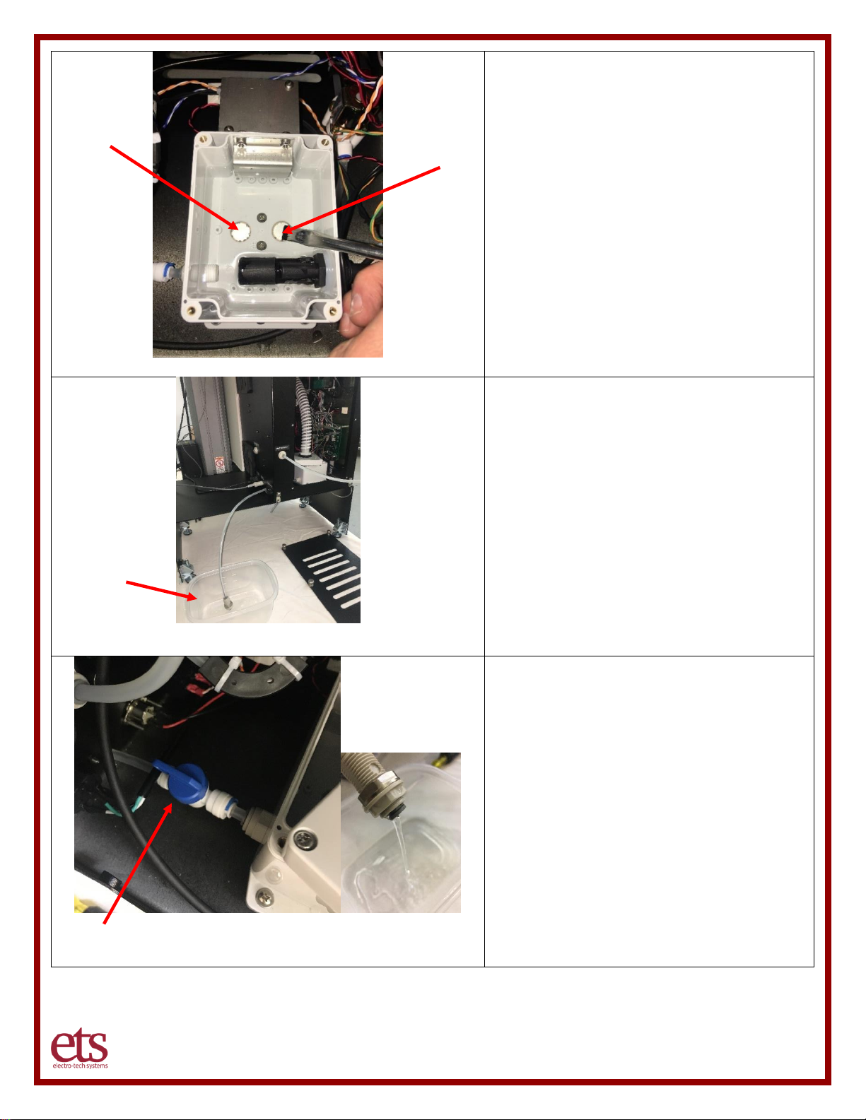
Step 5 – Clean the transducer
Clean the surface of the two transducers
(located at the bottom center of the basin
using the cleaning brush provided by ETS.
If not available or lost, utilize a soft clean
cloth or small soft brush (e.g. toothbrush)
to clean the surface of the transducer. Do
not use any tools with sharp edges –
scratching the transducer could damage it.
Step 6 – Prepare to drain the basin
After cleaning both transducers with the
brush, the contaminated water will need to be
drained out of the basin. In preparation,
place a small container at the end of the
drain hose to collect the water that flows out
of the hose. The container must allow the
hose to flow downward so the water can
gravity feed and drain out of the basin.
Step 6 –Drain the basin
Open the drain valve by turning it to the open
position as shown in the picture.
If the water does not flow, move or gently
bend the hose to help break any air
pockets/bubbles that may have formed that
could prevent the free flow of water.
Drain Valve (shown in the “Open” position)
Page 22
www.electrotechsytems.com 833-ENV-GURU (833) 368-4878 D00804 Revision B – 20190722 - Page 22
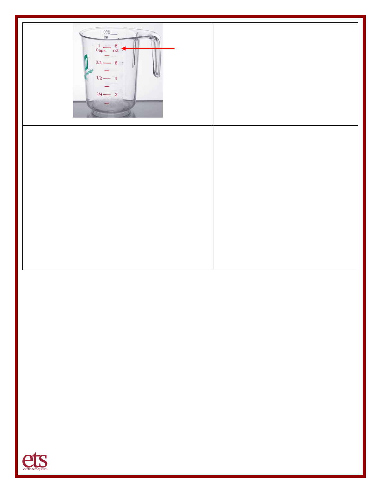
Step 6 – Flush the basin
Once the basin has drained, flush out the
basin twice with an 8-ounce cup of deionized
or distilled water each time. Do not exceed 8
ounces of water at a time.
Reference pictures in the previous steps.
Step 7 – Return the System to operation
Return the system to operation by:
• Close the basin drain valve so water
won’t pour out the drain hose.
• Replace the humidifier basin cover and
tighten the screws with the screwdriver.
• Replace the control unit side access
panel and tighten the thumbscrews
• Turn on the water supply on the 2.5
gallon water tank
• Restore power to the control unit by
plugging it in.
• Turn on the power switch on the control
panel
Page 23

www.electrotechsytems.com 833-ENV-GURU (833) 368-4878 D00804 Revision B – 20190722 - Page 23
VII. Warranty
Limited Warranties. Seller warrants that all goods manufactured and delivered hereunder shall (a)
conform to any samples, drawings, specifications or other written documents provided to Seller by
Buyer, or approved by Buyer to Seller and (b) be free from all defects in workmanship and material.
Buyer’s sole remedy against Seller for breach of either of the specifically mentioned warranty shall be
the repair or replacement, at Seller’s sole option, of the defective workmanship or material. Seller
expressly disclaims all other warranties, express and/or implied, including but not limited to those of
merchantability and fitness for a particular purpose. In no event shall Seller be liable, under either
warranty or otherwise, to Buyer in excess of the purchase price of the products paid to Seller by
Buyer. In no event shall Seller be liable for any loss or damage arising directly or indirectly from the
use of the product or for consequential or incidental damages. Seller’s specified warranties will
expire and lapse (i) for renewable items (such as gloves, iris ports and desiccants), sixty (60) days
from date of shipment and (ii) for all standard equipment and otherwise nonrenewable items, one
year from date of shipment.
Page 24

www.electrotechsytems.com 833-ENV-GURU (833) 368-4878 D00804 Revision B – 20190722 - Page 24
IX. Liquid Nitrogen Safety Addendum
Reference: http://engineering.dartmouth.edu/microengineering/ln2.html
Properties of Liquid Nitrogen (LN2)
1. It is extremely cold: 77.3K = -196C = -320F at atmospheric pressure. This can cause severe
frost bite.
2. On vaporization, it expands by a factor of 700; one liter of liquid nitrogen becomes 24.6 cubic
feet of nitrogen gas. This can cause explosion of a sealed container, or it can displace oxygen
in the room and cause suffocation without warning.
3. It can become oxygen enriched and cause ordinarily noncombustible materials to burn rapidly.
Precautions when handling liquid nitrogen
1. Treat liquid nitrogen and any object cooled with liquid nitrogen with respect.
2. Take care not to allow liquid nitrogen to be trapped in clothing near the skin.
3. Wear safety glasses or a face shield when transferring liquid nitrogen.
4. Wear gloves when touching any object cooled by liquid nitrogen. Gloves should be loose
fitting, so they could be thrown off if liquid were to pour inside them
5. Use only approved unsealed containers. Never pour it into a coffee thermos. Never seal it in
any container (it will explode).
6. Never dip a hollow tube into liquid nitrogen; it may spurt liquid.
7. Never use in a small poorly ventilated room, and never dispose of liquid nitrogen by pouring it
on the floor. It could displace enough oxygen to cause suffocation. Nitrogen gas is colorless
and odorless--the cloud that forms when you pour liquid nitrogen is condensed water vapor
from the air, not nitrogen gas.
8. Do not store liquid nitrogen for long periods in an uncovered container (on the other hand,
never totally seal a container). Because the boiling point of oxygen, 90.1K, is above that of
nitrogen, oxygen can condense from the air into the liquid nitrogen. If the air over the nitrogen
circulates, this liquid oxygen can build up to levels which may cause violent reactions with
organic materials; even materials which are ordinarily nonflammable. For example, a severe
clothing fire could result from ignition in the presence of liquid oxygen.
First Aid
• Suffocation: If person seems to become dizzy or loses consciousness while working with liquid
nitrogen, move to a well-ventilated area immediately. If breathing has stopped, apply artificial
respiration. If breathing is difficult, give oxygen. Call a physician. Keep warm and at rest.
• Frost bite: If exposed to liquid or cold gas, restore tissue to normal body temperature, 98.6F
(37C), followed by protection of the injured tissue from further damage and infection. Remove
or loosen clothing that may constrict blood circulation to the frozen area. Call a physician.
Rapid warming of the affected part is best achieved by using water at 106F (42C). Under no
circumstances should the water be over 112F (44C), nor should the frozen part be rubbed
either before or after rewarming. The patient should neither smoke, nor drink alcohol.
The above is first aid information is from the publication "Handle With Care", C 1996 Harsco
Corporation, Factory code 7950-8052.
Page 25

www.electrotechsytems.com 833-ENV-GURU (833) 368-4878 D00804 Revision B – 20190722 - Page 25
X. Liquid Nitrogen Cooling System Set-Up Addendum
The Nitrogen Cooling System cools a chamber by converting liquid nitrogen into a gas. In the
conversion process the gas is cooled to nearly -100F. Liquid is passed directly from the dewar to the
cryogenic solenoid valve through a stainless steel cryogenic transfer hose. The output of the valve has
a cap with a small orifice drilled through it. This cap acts as the pressure regulator for the system. As
the liquid nitrogen passes through the orifice, it is converted into a cold gas.
A low-pressure Dewar is required. This is determined by the Dewar pressure relief valve which can
range from below 22 PSI to above 235 PSI. For this system, a 22 PSI Dewar is required. When the
system is first turned on, there will be a small amount of nitrogen gas in the liquid nitrogen stream. The
nitrogen gas must be allowed to pass before any cooling will take place. Typically, this should happen
within the first 3-5 minutes, some may take longer. Adequate venting is a necessity.
PROCEDURE
1. Review proper safety procedures for Liquid Nitrogen and Dewar tank
use before starting!!
2. Attach the stainless steel cryogenic transfer hose to the liquid nitrogen output from the Dewar or
source.
3. Check the pressure gauge on the Dewar or Liquid Nitrogen Source. Pressure should be below
22 PSI. Be aware that as the valve cycles on and off, the pressure will increase in the Dewar when
the valve is off. The Dewar will relieve pressure at a specific pressure set by the auto relief on the
Dewar which is supposed to be 22 PSI for this application. This will cause the tank to vent most of
the time creating a hissing sound which is normal.
4. Holding the transfer hose with insulated gloves and pointing it away from anything, open the liquid
nitrogen output valve on the Dewar to bleed the tank until a solid thick cloud of gas comes out.
Once a cloud of gas is visible close the liquid nitrogen output valve on the Dewar.
5. Attach the open end of the transfer hose to the ETS Control Valve input.
6. Open the liquid nitrogen output valve on the Dewar.
7. Turn on the LN2 switch on the control panel to operate the valve.
8. Monitor the pressure. Periodically check the Dewar pressure to insure the pressure relief valve
is functioning properly and manually vent the Dewar if necessary.
EXPLOSION WARNING!! Do not block or seal the Dewar pressure relief valve or the tank will
explode. Monitor the pressure of the Dewar to insure the pressure relief valve is functioning
properly. Never completely seal liquid nitrogen in any container.
WARNING!! To avoid risk of bursting of the hose, always bleed liquid nitrogen from the
stainless steel transfer hose when the system is not in use. If the liquid nitrogen valve on the
dewar is open, pressure from the hose will be relieved normally through the dewar vent. If the Dewar
valve is closed, the liquid nitrogen must be bled from the line otherwise the hose will explode. The
vaporization expands by a factor of 700. One liter of liquid becomes 24.6 cubic feet of nitrogen gas.
SUFFOCATION WARNING – Due to the high evaporation rate of liquid nitrogen, never use unless
in a well ventilated area. If a person seems to become dizzy or looses consciousness, move to
a well-ventilated area immediately.
FROST BITE WARNING – Do not allow liquid nitrogen to come in contact with skin or clothing.
 Loading...