

Page 1

Integrated Heating
System
Model 5474
Model 5474A
Model 5474L
Operating Manual
7/05/06
www.electrotechsystems.com
Page 2

TABLE OF CONTENTS
1.0 GENERAL DESCRIPTION 1
2.0 INSTALLATION 2
2.2 Wiring 2
2.3 HEPA Filters
3.0 OPERATION 4
4.0 WARRANTY 5
2.1 Mechanical Installation 2
3
Page 3
1.0 GENERAL DESCRIPTION
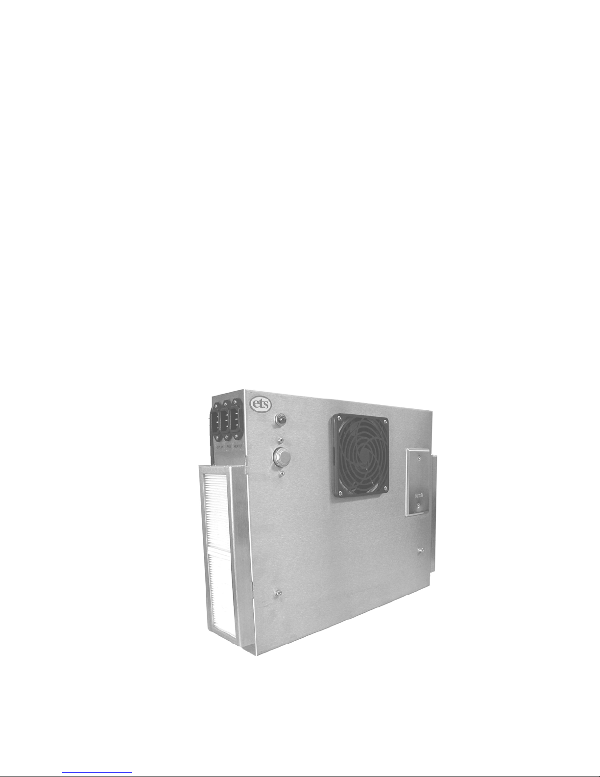
The Model 5474/5474A Integrated Heating System, shown in Figure 1, is
a 500 Watt heating system that consists of a stainless steel strip heating
element, 135°F (57°C), thermal overload sensor, power on indicator and a
110 cfm fan for use in small controlled environment chambers. In addition,
a weather-tight AC accessory outlet box with a GFCI outlet for 115 VAC or
a duplex North American outlet for 230 VAC is provided. The Model 5474
houses the components in a stainless steel enclosure measuring
16”Wx13”Hx3.125”D (41x33x8 cm). The 5474L, a larger version of the
5474, measures 30”Wx16.875”Hx4.125”D. On all 5474’s the heater, fan
and AC outlet are IEC power input modules.
The Model 5474A utilizes a stainless steel enclosure with 4 replaceable
HEPA filters and a gasket seal for installation onto the surface of the
chamber. The standard unit incorporates 3 IEC power connectors to
accept standard IEC power cords. Otherwise, the Model 5474A operates
the same as the Model 5474.
The system can be customized to meet most user requirements by adding
or removing accessories.
Figure1: Model 5474A Integrated Heating System
1
Page 4

2.0 INSTALLATION
2.1 Mechanical Installation
The Model 5474/5474A/5474L is designed for vertical mounting,
but may also be mounted horizontally if insulation is added to the
rear of the unit. (Since heat rises and the distance between the
heater and the mounting surface will be only 1.5" (4 cm) the
mounting surface will be hotter than with the vertical mount. If a
plastic surface is used and the heater is run at maximum
temperature the distortion temperature of the material may be
exceeded.)
The standard system requires 4, #8-32 screws for mounting. The
hole pattern is a 12”x12” (30.5 cm) square. The mounting hole
diameters are .188” (5 mm). The 5474L requires 6, #8-32 screws
in which the mounting holes measure 15.875” vertically and 11.5”
from the center hole to the outside holes.
The Model 5474 enclosure is mounted directly against the surface.
If insulation is used it should be cut to the full dimensions of the
enclosure.
The Model 5474A has a ¼” (6 mm) thick foam rubber gasket. If
insulation is used it should be cut so that it fits inside the gasket.
When tightening the mounting screws, compress the gasket
approximately 50%, or whatever the insulation used allows. If the
insulation is thicker than ¼” (6 mm) then cut it the size of the
enclosure and mount the enclosure on the surface.
2.2 Wiring
The Model 5474 with an AC fan incorporates IEC power input
modules that accept the standard IEC power cord. The inputs are
labeled as follows:
Front: Heater
Center Fan
Rear AC Accessory
The system is configured at the factory for either 115 VAC/60 Hz or
230 VAC/50 Hz operation. However, the AC Accessory outlet must
remains the standard North American type for 230 VAC units. It is
suggested that a power strip corresponding to the power plugs
2
Page 5
being used be fitted with a North American plug to use the installed
AC outlet directly.
If a DC fan is used then the center connector is a 5 mm power
module connector.
2.3 HEPA Filters
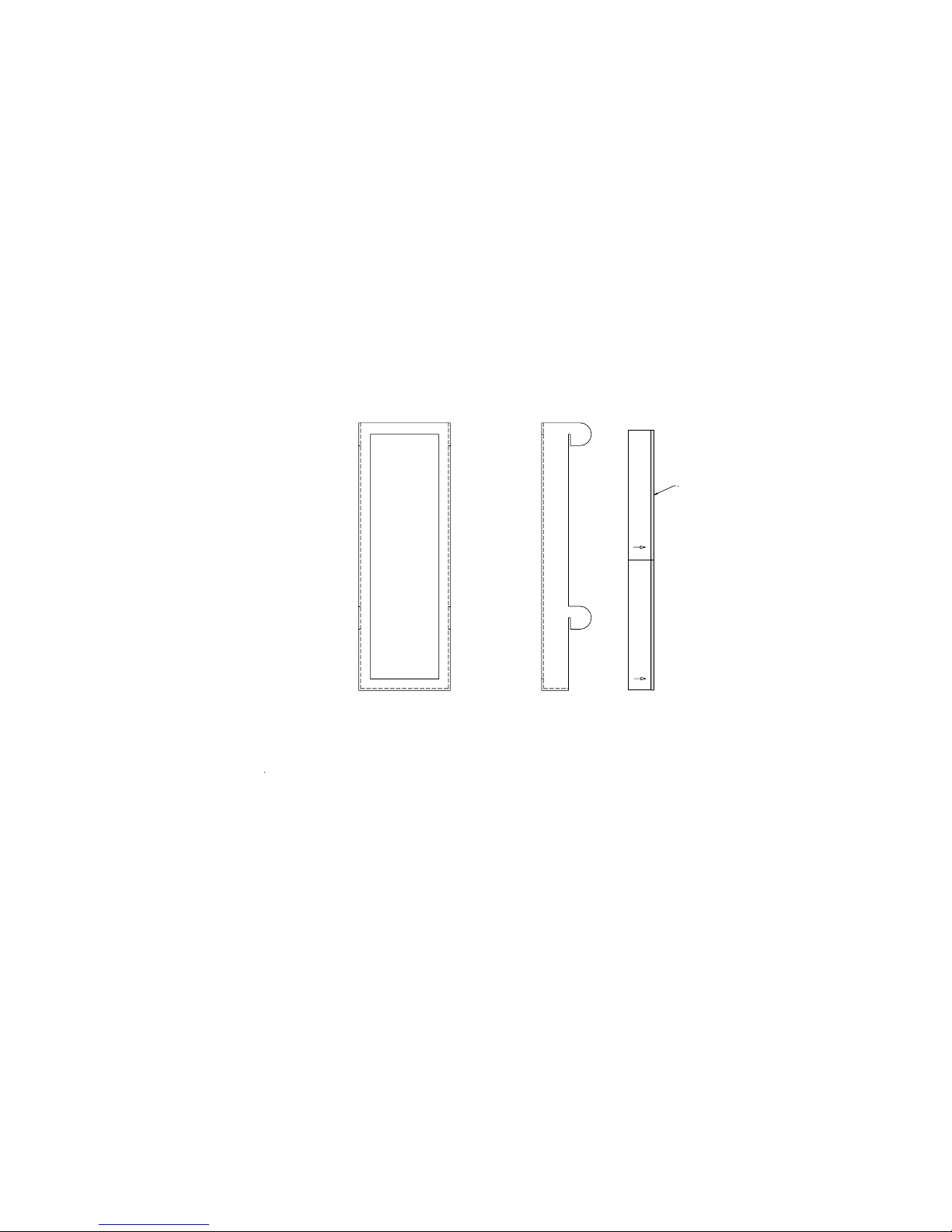
The Model 5474A is available with HEPA filtering over the intake
ports located on both sides of the unit. Each side requires 2 filters
that are held in place by stainless steel brackets as described in
Figure 2.
Gasket
Install HEPA Filter in to B ra c k et, g a s ke t fa c ing towar d m o u n tin g ta b s .
Install Bra c k e t on to s id e (s) o f s c re e n . Ins e rt th e fou r (4 ) tab s in to th e fo u r (4 ) s lo ts
on the side(s) of the screen. Push in firmly. Pull down firmly to lock bracket into place.
Figure 2: HEPA Filter installation
Replacement filters are available from ETS. Order Part #500-6613.
3
Page 6

3.0 OPERATION
The Model 5474/5474A/5474L Integrated Heating System is designed to
operate with a temperature controller such as the ETS Models 5100 or
5200 series. The Heater power cord plugs into the control outlet labeled
“INCREASE”. The Fan power cord plugs into an external outlet.
The Model 5474/5474A/5474L Heater requires constant air circulation
for proper operation. If the fan is turned off and the heater is run at
full power it may result in damage to the system.
NOTE
7/05/06
4
Page 7

4.0 WARRANTY
Electro-Tech Systems, Inc. warrants its equipment, accessories and parts of its
manufacture to be and remain free from defects in material and workmanship for a
period of one (1) year from date of invoice and will, at the discretion of Seller, either
replace or repair without charge, F.O.B. Glenside, similar equipment or a similar part to
replace any equipment or part of its manufacture which, within the above stated time, is
proved to have been defective at the time it was sold. All equipment claimed defective
must be returned properly identified to the Seller (or presented to one of its agents for
inspection). This warranty only applies to equipment operated in accordance with
Seller's operating instructions.
Seller's warranty with respect to those parts of the equipment which are purchased from
other manufacturers shall be subject only to that manufacturer's warranty
.
The Seller's liability hereunder is expressly limited to repairing or replacing
any parts of the equipment manufactured by the manufacturer and found to
have been defective. The Seller shall not be liable for damage resulting or
claimed to result from any cause whatsoever.
This warranty becomes null and void should the equipment, or any part
thereof, be abused or modified by the customer of if used in any
application other than that for which it was intended. This warranty to
replace or repair is the only warranty, either expressed or implied or
provided by law, and is in lieu of all other warranties and the Seller denies
any other promise, guarantee, or warranty with respect to the equipment or
accessories and, in particular, as to its or their suitability for the purposes
of the buyer or its or their performance, either quantitatively or qualitatively
or as to the products which it may produce and the buyer is expected to
expressly waive rights to any warranty other than that stated herein.
ETS must be notified before any equipment is returned for repair. ETS will issue an
RMA (Return Material Authorization) number for return of equipment.
Equipment should be shipped prepaid and insured in the original packaging. If the
original packaging is not available, the equipment must be packed in a sufficiently large
box (or boxes if applicable) of double wall construction with substantial packing around
all sides. The RMA number, description of the problem along with the contact name and
telephone number must be included in formal paperwork and enclosed with the
instrument. Round trip freight and related charges are the owner’s responsibility.
WARNING
WOODEN CRATES MUST NOT BE USED. PACKAGING OF DELICATE
INSTRUMENTS IN WOODEN CRATES SUBSTANTIALLY INCREASES THE
CONTENT’S SUSCEPTIBILITY TO SHOCK DAMAGE. DO NOT PLACE
INSTRUMENTS OR ACCESSORIES INSIDE OTHER INSTRUMENTS OR
CHAMBERS. ELECTRO-TECH SYSTEMS, INC. WILL NOT ASSUME
RESPONSIBILITY FOR ADDITIONAL COST OF REPAIR DUE TO DAMAGE
INCURRED DURING SHIPMENT AS A RESULT OF POOR PACKAGING.
5
 Loading...