

Page 1
CHARGED PLATE DETECTORS
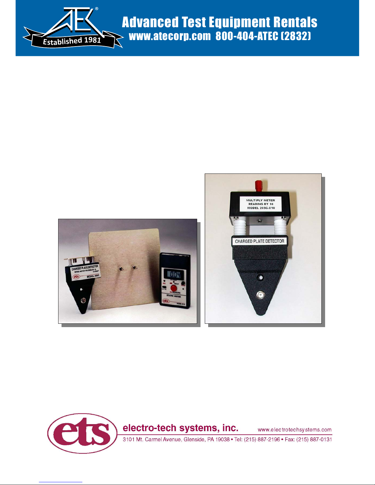
Model 205C and 205C-x10
Instruction Manual
4-09
Advanced Test Equipment Rentals
www.atecorp.com 800-404-ATEC (2832)
®
E
s
t
a
b
l
i
s
h
e
d
1
9
8
1
Page 2
1.0 GENERAL
The Model 205C and 205C-x10 Charged Plate Detectors are used in conjunction with
the ETS Model 212 Static Meter. They snap onto the front of the Meter providing a
convenient and economical approach for performing electrostatic measurements
requiring a charged plate monitor. Typical charged plate tests consist of measuring
ionizer balance and decay, static propensity of floors and footwear, triboelectric charge
evaluation of material and objects, plus evaluation of the effectiveness of personnel
grounding systems. The optional Model 208B-1200 Volt Charging Source enables the
system measure ionization neutralization time, voltage suppression, static dissipation
and using the 208B-1000 Volt Charging Source Calibration Unit, system calibration.
2.0 EQUIPMENT DESCRIPTION
2.1 Model 212 Static Meter
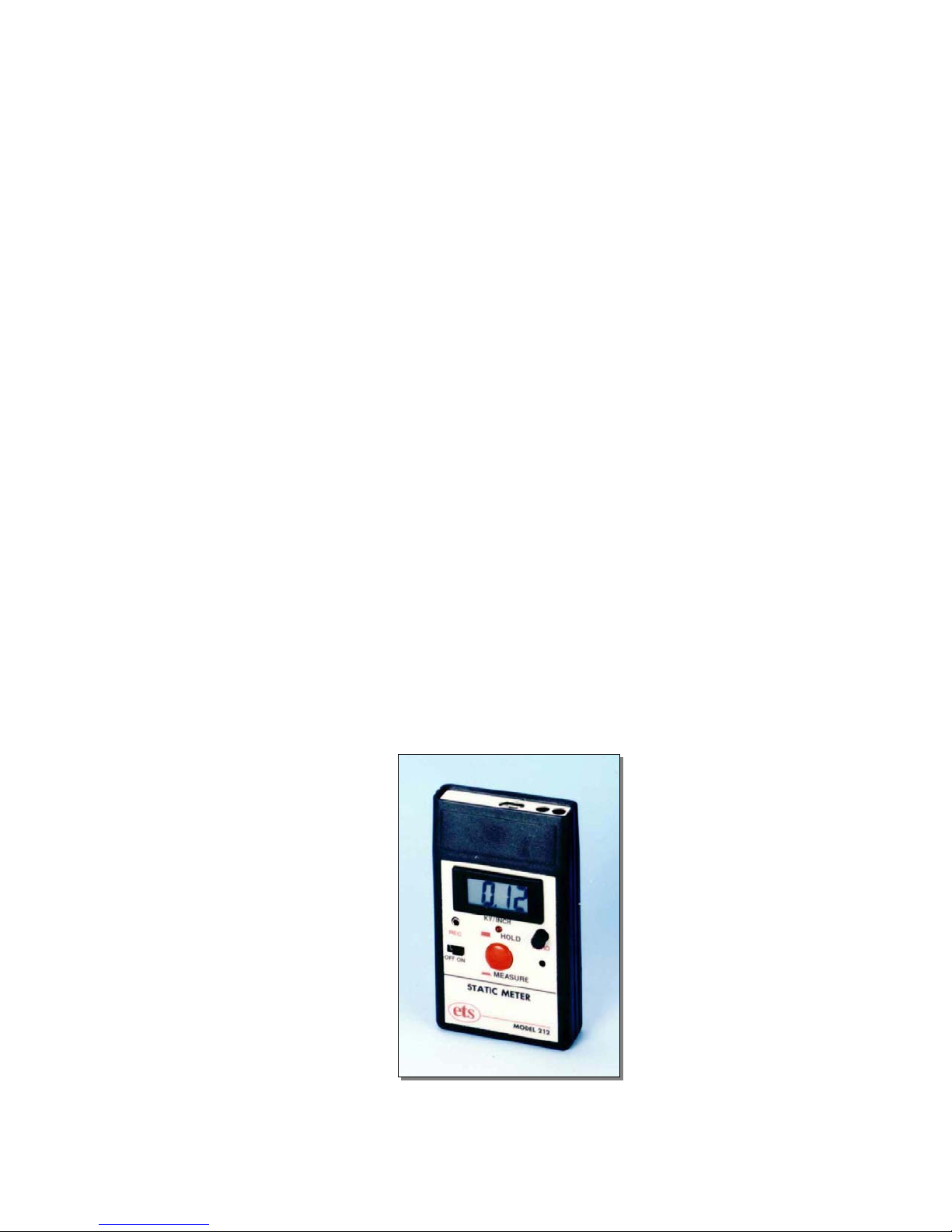
The Model 205C and 205C-x10 are used in conjunction with the ETS Model 212 Static
Meter, shown in Figure 2.1-1. The Meter incorporates a non-contacting, chopper type
field sensor with “MEASURE and HOLD” functions. In the “MEASURE” mode, the Static
Meter provides continuous measurement. The “HOLD” mode stores the last
measurement, permitting operation in special situations such as measuring static
charges inside an opaque bag or inside production equipment. The meter is “zeroed”
easily with an external ZERO ADJUST control and normally does have to be re-zeroed
between measurements.
The chopper stabilized sensor enables the Model 212 to accurately measure
electrostatic fields in areas using air ionization. The Meter is powered by a 9V battery
and features a conductive case as well as a convenient snap-on wrist strap cord to
provide a hard ground connection. The Model 212 standard measurement range when
used as a field meter is ±20kV at 1 inch (25mm) when measuring a large planar target
in free space.
Figure 2.1-1: Model 212 Static Meter
2.2 Model 205C and 205C-x10 Charged Plate Detectors
1
Page 3
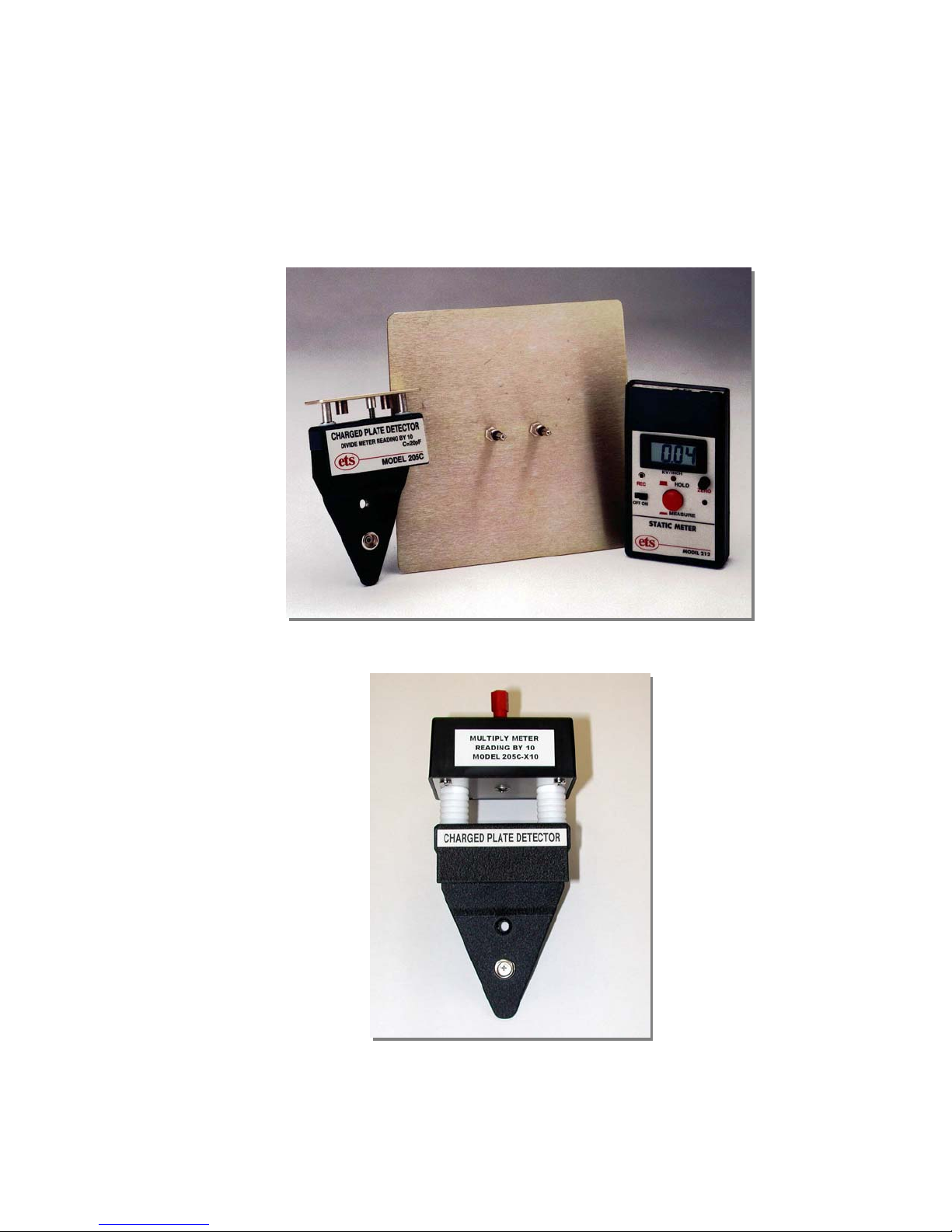
These charged plate detectors attach to the front of the Model 212 Static Meter.
The standard Model 205C along with the optional 6”x6” Detector Plate and the
Model 212 shown in Figure 2.2-1 increases the sensitivity of the measurement
system by a factor of 10 and is designed for low voltage measurements up to 2
kV. The Model 205C-x10, shown in Figure 2.2-2, decreases the sensitivity of the
measurement system also by a factor of 10 and is designed for high voltage
measurements up to 20 kV.
Figure 2.2-1: Standard Model 205C with optional 6”x6” Detector Plate
Figure 2.2-2: Model 205C-x10 Charged Plate Detector
2.2.1 Standard Model 205C
2
Page 4

Applying 2000 Volts to the plate surface of the standard Model 205C will
indicate full scale on the Static Meter (divide meter reading by 10. A meter
reading of 20.00 kV indicates 2 kV on the plate). The standard Model
205C also has 20 pf capacitance specified in ESDA STM3.1 required for
ionizer decay time measurements. It is designed for high resolution (±1 V),
low voltage applications usually found in ESD controlled areas. An
optional 6”x6” (152x152mm) square detector plate attaches to the
1”x3”(25x76mm) Model 205C detector plate to provide full size charged
plate monitor measurement capability. System drift is less than 2
Volts/second.
Note: If the Model 205C is used to measure ionization decay the rate will
be approximately 10 times faster with the 6x6” (152x152mm) plate. This is
a result of the area of the larger plate being approximately10x larger than
the smaller plate.
2.2.2 Model 205C-x10
The Model 205C-x10, shown in Figure 2.2-2, is designed for
measurements up to a maximum of 20kV. Applications include static
propensity and static charge generation in non-ESD controlled areas such
as office buildings, factories, conveying systems etc. This unit does not
have the specified 20pF capacitance since it is not intended to measure
ionizer decay time. The detector plate is covered by a plastic cover to
reduce electrostatic shock to the operator.
3.0 OPERATION
To utilize the Static Meter as a field measuring instrument only, simply depress the push
button and bring the Meter towards the surface being measured. At a distance of 1 inch
(25mm), read the magnitude and polarity. Depress the MEASURE/HOLD button again
(Red LED on) to hold the reading. All measurements are normally referenced to the
potential of the user, which may or may not be at ground. To obtain a solid ground
reference, connect the Meter to ground using the supplied ground cable connected to
the snap located on the bottom of the Meter.
To convert the Model 212 to a charged plate monitor, attach the either the standard
Model 205C or the Model 205C-x10 Charged Plate Detector to the front of the Static
Meter as shown in Figure 3.0-1. Slide the Charged Plate Detector over the front of the
Static Meter and snap in place. The Model 212 ground cable can now be connected to
the Model 205C ground snap if desired. To measure charge generated by any activity,
connect a probe, wrist strap or other appropriate connection to the detector plate jack.
Ground the detector plate momentarily then activate the Static Meter. Any voltage
generated will be transferred to the plate and be measured by the Static Meter.
NOTE: Static charges on insulators cannot be transferred to the charged plate by wire.
3
Page 5
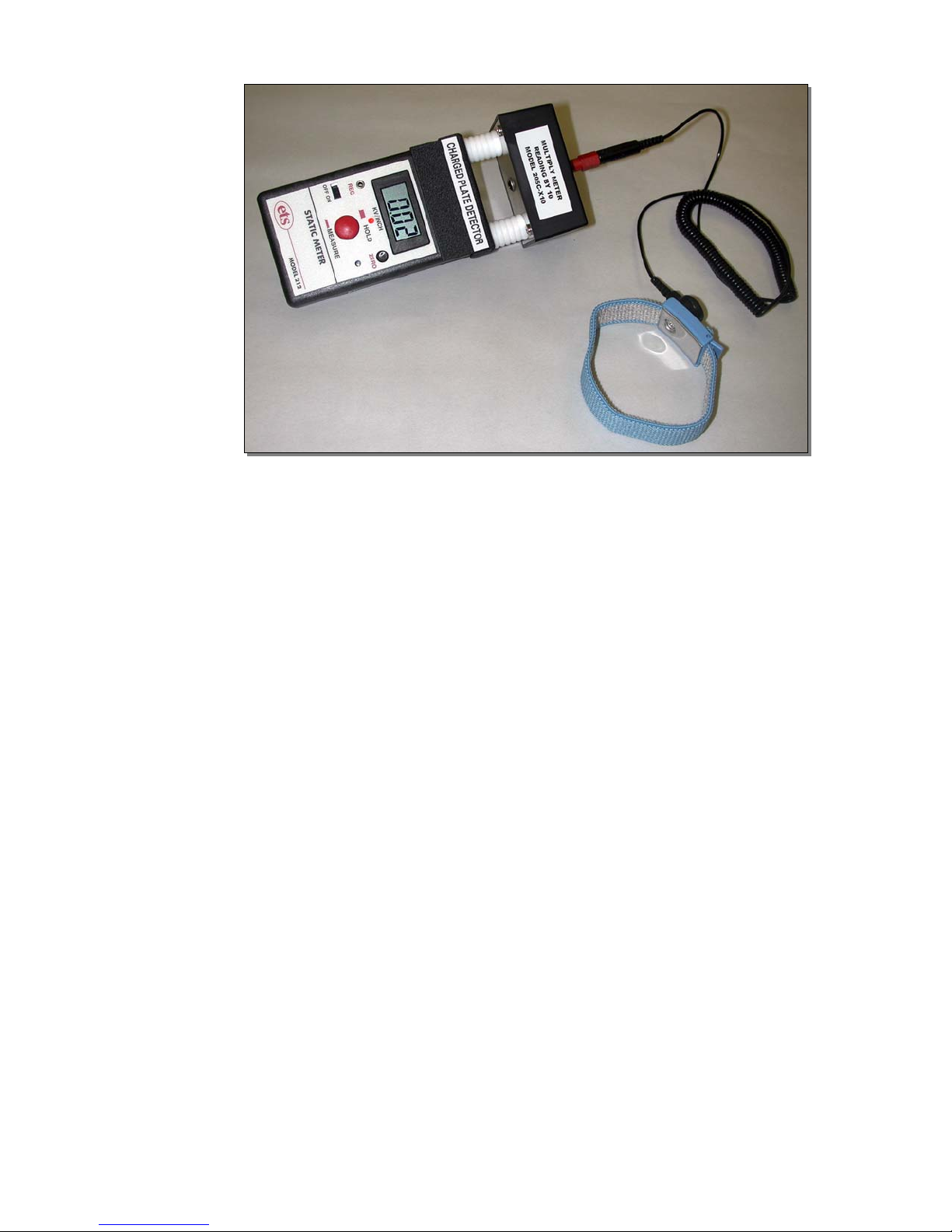
Figure 3.0-1: Charged Plate Monitor System Set Up
To perform a test first ground the detector plate momentarily, activate the Static Meter,
then take a measurement. For those measurements requiring the handling of static
dissipative materials, it is recommended that measurements be performed by two
people: one person to operate the instrumentation and the other to handle the material.
This is necessary to prevent any charge build-up on the material from being bled off
through the grounded operator.
4.0 TEST PROCEDURES
The Model 205C Charged Plate Detector (along with the optional Model 208B Charging
Source) is capable of performing many of the tests normally performed with laboratory
equipment. The following describes recommended procedures for performing the most
common CPM tests.
4.1 Ionizer Balance
This test is performed with the standard Model 205C. Hold the Static Meter with
the Charged Plate Detector approximately 12 inches (305mm) in front of the
ionizer. Momentarily ground the detector plate, then depress the push button.
Turn on the ionizer and observe the meter reading for approximately 15 seconds.
The meter should read less than ±10 volts.
4.2 Static Propensity
This test measures the static charge build-up on personnel walking across a floor
or performing a defined step test. It is used to evaluate flooring and footwear.
However, this test procedure also applies to any personnel activity that results in
a static charge being generated. Either the standard Model 205C or the Model
205C-x10 may be used for this test. In ESD controlled areas voltages generated
are usually quite low and the standard Model 205C is the most appropriate unit.
4
Page 6

In uncontrolled areas, especially when the relative humidity is very low many
kilovolts can be generated and the Model 205C-x10 should be used.
The test set up consists of attaching the Charged Plate Detector to the front of
the Static Meter. Connect a wrist strap or a probe to the Charged Plate Detector.
The test subject puts on the wrist strap.
Before starting the test, the test subject should be momentarily grounded before
taking a measurement. The voltage displayed on the Static Meter is the voltage
generated by the test subject during the activity.
4.3 Triboelectric Charge Analysis
This test is used with the standard Model 205C plus the addition of the optional
6” x 6” detector plate. The whole assembly should be mounted onto a tripod. First
momentarily ground the detector plate before taking a measurement. Take the
material being tested and rub it with an appropriate second material, then place
the test material on the detector plate. The voltage measured is a relative
indication of the triboelectric charging characteristics of the material.
If the decay time of the test sample is desired, the Model 212 must be used in
conjunction with a timing device such as a stopwatch.
4.4 Ionizer Neutralization Time
This test measures the time required for an ionizer to neutralize charge on an
object. It is also referred to as "Ionizer Decay Time". This test requires the
optional Model 208B Charging Source that has an output of 1200 Volts.
Place the Model 212 with the standard Model 205C 12 inches away from the
front of the ionizer. Momentarily ground the detector plate. Activate the Model
208B and touch it to the detector plate. The Static Meter should indicate a
reading greater than 1000 volts. Immediately turn on the ionizer and measure the
time for the charge on the detector plate to bleed down to zero using a timing
device such as a stop watch.
Note: When the Model 205C is used to measure ionization decay the rate will be
approximately 10 times faster with the 6x6” (152x152mm) plate. This is a result
of the area of the larger plate being approximately10x larger than the smaller
plate.
4.5 Static Dissipation
This test measures the time required for a charged person to bleed off charge
when a static control procedure is implemented such as stepping onto a
conductive floor or sitting down in a conductive chair. The test set up in Section
4.4 is used. The test subject wears a wrist strap or holds onto a probe for this
test.
5
Page 7

Momentarily ground the test subject then turn on the Charging Source and touch
it to the test subject. The Static Meter should indicate a reading greater than
1000 Volts. With the test subject initially standing on an insulated surface,
immediately step onto the surface being evaluated. Measure the time for the
voltage on the test subject to bleed down to zero or some established level such
as 100 V.
4/09
6
 Loading...