

EtroVISION N50 Quick Installation Manual
N50
A
E
A B C
Slide A over
cover B
Fixed B on
Screw A into
A A B C
EV8580
Series
Quick
Installation
Guide
www.etrovision.com
+886-2-2655-1518
Technical Support: etrotech@etrovision.com
Sales Contact: etrosales@etrovision.com
Install EtroScan on a Windows PC
- EtroScan™ is a utility is used to configure network
settings for cameras & video servers. EtroScan™ is
available on the CD-ROM or can be downloaded at
http://www.etrovision.com/Support/.
- Run Setup.exe to install EtroScan.
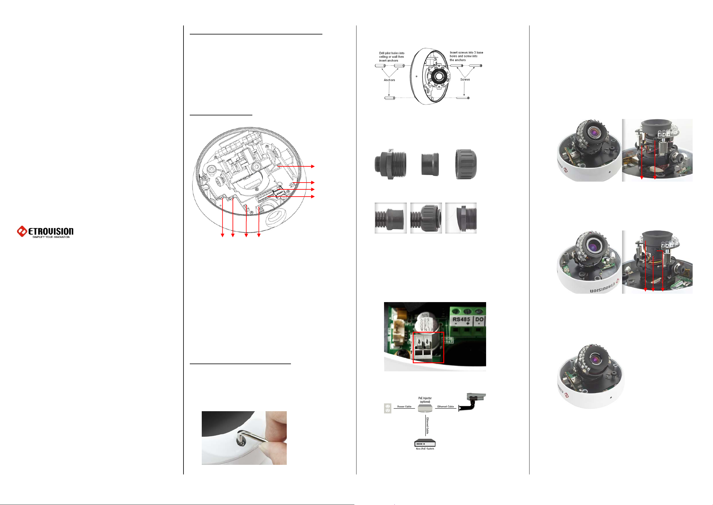
Camera Interior
F
G
H
B C D
A. Audio in
B. Audio out
C. 2 pin wafer for external WiFi dongle
D. Power into power cable
E. RJ45 network port
F. Factory default button
G. Micro SD card slot
H. RS485 RS485 DO DO DI DI
- + - + - +
Basic Physical Installation
It is recommended leaving the plastic dome covering on
until camera installation is complete.
1. Unscrew the screws securing the dome, and pull off
dome cover.
2. Drill 3 pilot holes and insert anchors. Use screws to
affix the camera base to the ceiling or wall.
3. Prepare conduit, and slide necessary cables through
tubing. After subsequent cabling is done, insert tubing
into A and screw C on to A.
tubing to
4. Connect power; there is no power button, recycling
power restarts the camera.
Insert power cabling into the camera’s power 2-pin
input. There is no +/- designation, so the red &
black lines can be inserted either way. The camera
supports 8-24V AC/DC power.
Power can also be provided via PoE.
5. Insert Micro SD card (if applicable)
to tubing
camera
6. Using the label on the digital I/O terminal, connect the
digital I/O (if applicable)
7. Insert Ethernet cable
8. Adjust the camera lens using tilt & swivel controls as
needed (refer to sections 5 & 7 for viewing video)
EV8580x-Cx Vari-Focal Lens Series:
A. N&F: Focus Adjustment
B. W&T: Zoom Adjustment
B
EV8580F-C Vari-Focal Lens Model:
A. N&F: Focus Adjustment
B. Focus Lock
C. W&T: Zoom Adjustment
EV8580x-Mx / N50x Motorized Lens Series:
The product uses a motorized lens which requires
no manual adjustment by hand. Adjust the lens via
the camera’s web IE user interface.
9. If dome fogging is a concern, peel and place the silica
gel packet on the inside of the dome.
10. Place the dome cover on the camera; take care that
dome cover seal remains intact
11. Tighten the screws to fix dome cover
IR Sync. function:
To the Camera
A B C D
1234
Access IP Camera Web Interface
L Bracket Installation
Note: Only Applicable if L Bracket Option Purchased
The L bracket (AC-BKL00) is an accessory that can be
purchased along with the camera. The following
instructions apply to installation using the L Bracket.
1. Run RJ45 and power cables through L bracket. If a hole
is preferred for running cable, then cut a hole in the
wall if necessary.
Screw A into the camera opening. Run cables into
camera and B/C into A. The cable length may need to
be adjusted to fit cabling in camera and plug within A.
Screws D on to A to secure water proof plug.
5. Affix camera housing to L bracket and secure by
tightening the screws; be sure to pass cabling into hole
in the camera housing.
If using an external IR trigger, then connect the external IR
device to the camera’s 2-pin IR Sync port.
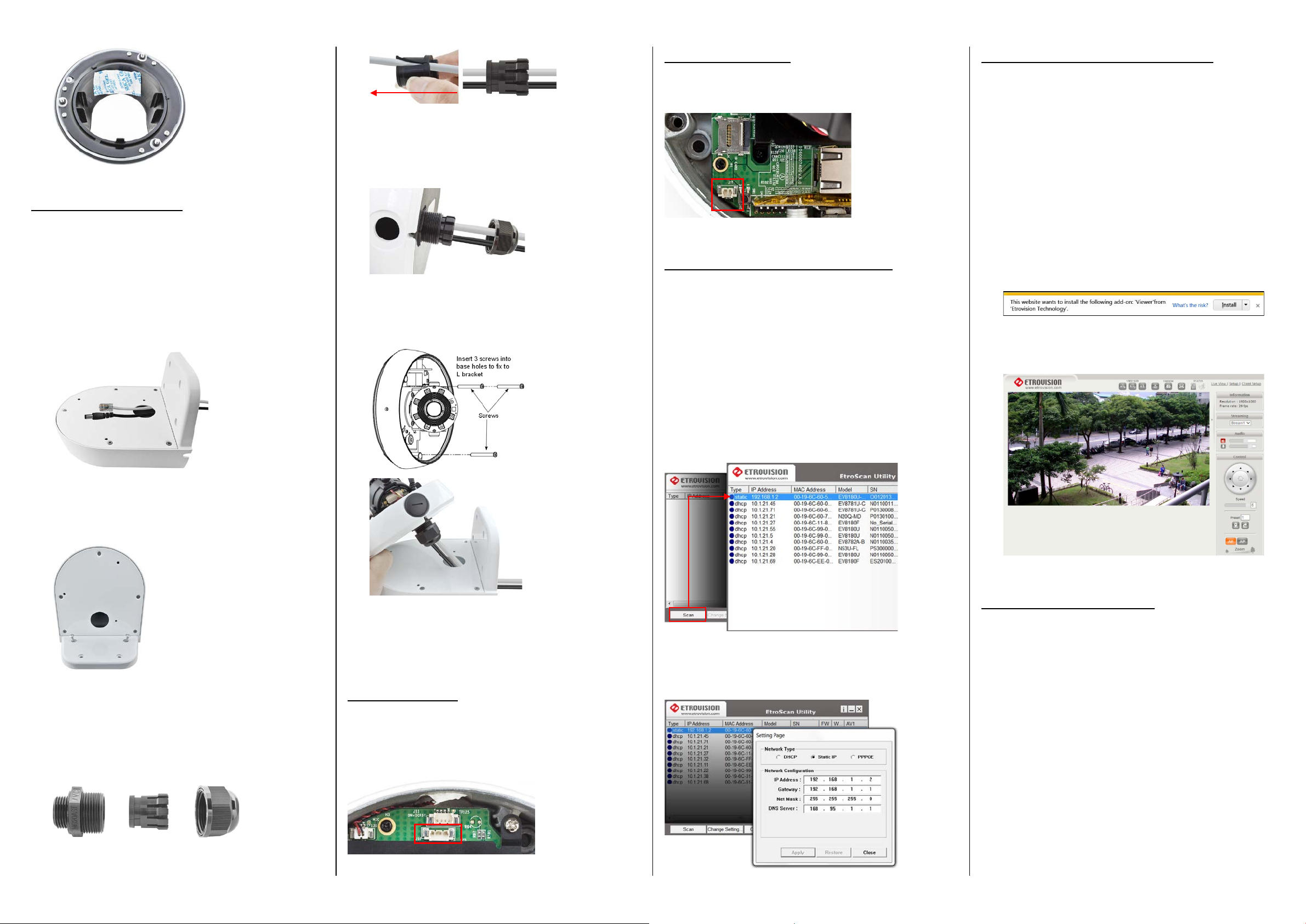
Configure the Network Settings
The factory default IP address settings:
IP Address: 192.168.1.2
Subnet Mask: 255.255.255.0
Gateway: 192.168.1.1
Run EtroScan™ (program available via Start All
Programs Etrovision Technology menu).
When accessing an IP camera using the web interface for
the first time (or when the IP address changes), some
configuration for ActiveX controls are required.
1. Open an IE browser
2. Type in the IP address in the URL: http://<IP ADDRESS>
(e.g. http://10.1.21.53)
3. On first connecting to a camera, IE will probably
prompt to install Active X components which are used
in the camera web UI. Click Install to continue.
Following this step, a User Access Control window will
also appear to confirm installation.
4. Once the process is complete, the Live View will be
displayed.
2. Drill pilot holes for L bracket and insert wall anchors
3. Secure the L bracket to the wall by screwing into the
anchors.
4. Prepare cables and waterproof connection. Remove C
from B. Only remove caps from B that will be used for
cables (e.g. network power) Slide cables into tubes
leaving approx. length of cable to feed into camera and
plug into port.
6. Please continue with setup from step 3.4 in Basic
Physical Installation, and if necessary please refer to
Basic Installation for more other information.
BNC Connector
The camera can provide video out via BNC cable. The BNC
cable provided has a 2 pin plug. When connecting the BNC
cable for SDTV video out, connect the BNC cable to pin 3 &
4 as shown below.
Scan displays all devices on the network. Use 192.168.1.2 IP,
Model, and MAC Address to identify a specific
camera/video server.
Use Change Setting to change network settings. After
clicking Apply, enter “pass” for the root password when
prompted.
Factory Default Settings
There are 2 methods for restoring the factory default
settings:
1. Power on the camera, remove the plastic cover from
the reset pin and touch the pin to metal for 6 seconds.
The camera will revert to factory default settings (e.g.
IP will reset to 192.168.1.2).
2. web UI Setup (System -> Factory Default) ; network and
user account data can be saved if desired. Please refer
to the User’s Manual for more information on the web
UI Factory Default functionality.
Slide C over B.
4 pin for SDTV plug into 3 and 4 pin
 Loading...