

Page 1

Users Manual
EV8x8x Models
Firmware Version 1.0.7
Document Version 1.2
Page 2

About This Guide
The User’s Manual provides functionality and instructions for the 1080p/5M series
which includes:
• EV8180A
• EV8180F
• EV8180U
• EV8180U-YN
• EV8580F
• EV8580U-B
• EV8580U-C
• EV8580A
• EV8780U
• EV8781A
• EV8781U-C
• EV8781F
Before Using the IP Camera/Video Server
Check the PC requirements
Review the OS platform requirements
Read an special and import precautionary information
Having basic knowledge of network setup and configuration will be helpful
Disclaimer
© 2010 Etrovision Technology. All rights reserved.
EtroLink™ & AnyUSB™ are trademarks of Etrovision Technology; other product or
service names mentioned herein are the trademarks of their respective owners.
Information contained in this document may be superseded by updates. No
representation or warranty is given and no liability is assumed by Etrovision
Technology with respect to the accuracy or use of the information, or infringement of
patents or other intellectual property rights. No licenses are conveyed, implicitly or
otherwise, under any intellectual property rights.
Page 3

1 INTRODUCTION..............................................................................1
2 THE LIVE VIEW................................................................................2
2.1 Setup........................................................................................................... 3
Set the Snapshot/Recording Path............................................................... 3
2.2 Controls and Status.....................................................................................3
2.3 Digital Zoom................................................................................................ 4
2.4 Information.................................................................................................. 4
2.5 Streaming....................................................................................................4
2.6 Audio........................................................................................................... 5
2.7 Control (PTZ Control)..................................................................................5
3 SETUP .............................................................................................6
3.1 System – Information .................................................................................. 7
3.2 System – Generic Setting............................................................................7
Camera Name.............................................................................................7
System Time............................................................................................... 8
Digital Input................................................................................................. 8
LED............................................................................................................. 8
HTTP Port................................................................................................... 8
Language.................................................................................................... 9
3.3 System – User Account Management.........................................................9
3.4 System – Maintenance..............................................................................10
Firmware Update.......................................................................................10
Export/Import Camera Configuration.........................................................13
Restore Factory Default ............................................................................ 13
Reboot Device...........................................................................................13
3.5 System – Local Storage............................................................................ 13
3.6 System – Record Setting...........................................................................14
3.7 Network – IP Setting..................................................................................14
3.8 Network – Streaming.................................................................................15
3.9 Network – DDNS.......................................................................................15
3.10 Video/Audio – Video Setting...................................................................... 16
TV Out Mode............................................................................................. 16
Resolution Mode (EV8x80F Models Only) ................................................ 17
Profile Setting............................................................................................ 17
3.11 Video/Audio – Audio Setting......................................................................18
3.12 Video/Audio – Color Setting ......................................................................19
Page 4

3.13 Event Handle – Event Rule.......................................................................19
3.14 Event Handle – Event Server.................................................................... 20
Email Setting............................................................................................. 21
Network Storage ....................................................................................... 21
3.15 Event Handle – Motion Detection.............................................................. 21
3.16 PTZ Control – Serial Setting...................................................................... 22
3.17 System Log – View Log............................................................................. 22
3.18 System Log – Remote Log Setting............................................................ 23
4 STREAMING VIDEO......................................................................24
Authentication ........................................................................................... 24
5 ADDING A CAMERA TO AN NVR..................................................26
5.1 RTSP URL.................................................................................................26
5.2 Administrator User & Password ................................................................ 27
6 FIREFOX & CHROME....................................................................28
Page 5

1
1 INTRODUCTION
This guide is for the use with the 1080p/5MP series using firmware version 1.0.7.
Please pay close attention to areas that are highlighted in YELLOW. These areas
highlight special instructions for this firmware release.
Page 6
2
2 THE LIVE VIEW
The IP camera web interface is made up of two main pages: the Live View page and
the Setup page. The Live View provides the current display from the IP camera
along with selected settings, configuration and functionality.
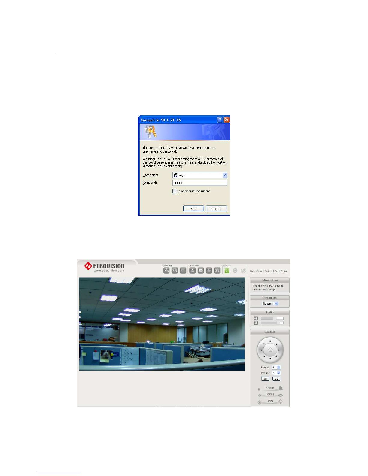
A login is required to access the web UI. The administrator username is “root”, and
the password by default is “pass”.
After logging into the IP camera via the browser, the user is first presented with the
Live View interface.
Below is an example of the Live View page. Following the screenshot is a discussion
of the different areas within the Live View page.
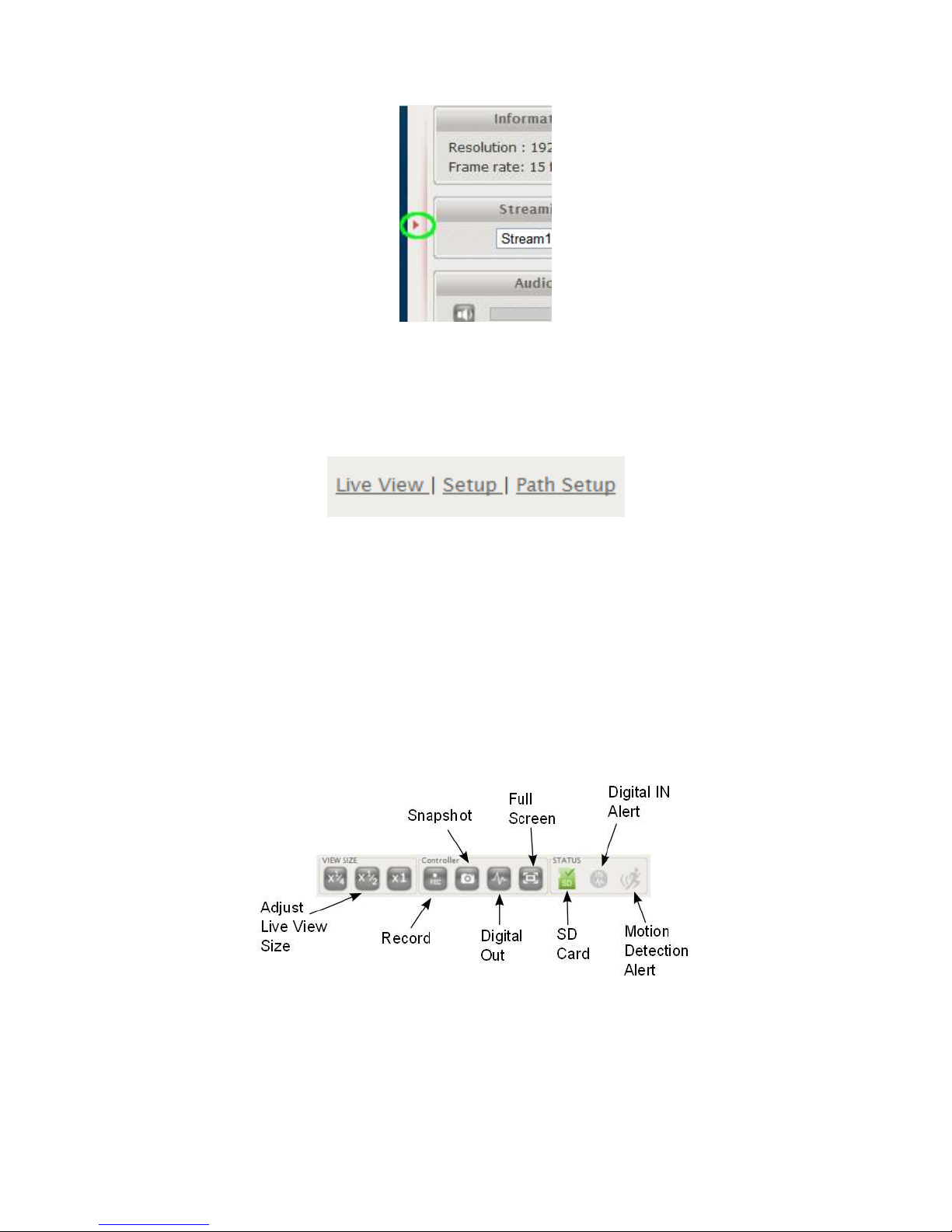
The right hand panel (Information, Streaming, Audio, Control) can be hidden by
clicking the small arrow bordering the video and Streaming pane.
Page 7
3
Click the arrow (highlighted in green) to hide/display the right side panel.
2.1 Setup
In the top right corner of the screen are three links.
• Live View: the main viewing screen with various controls.
• Setup: provides the interface for most of the camera configuration.
• Path Setup: sets the default Snapshot/Recording path on the PC
Set the Snapshot/Recording Path
Select Path Setup and then select the directory where Live View will write
snapshots/recordings.
2.2 Controls and Status
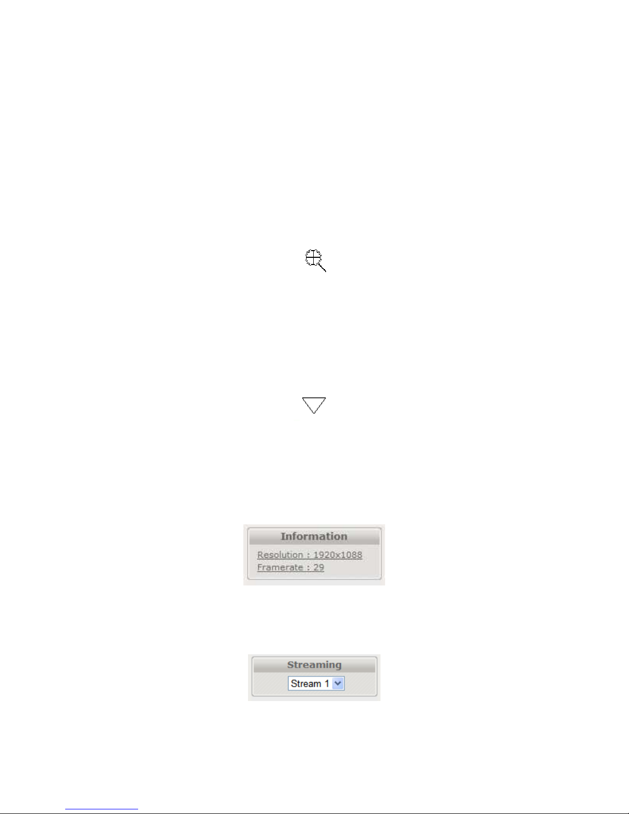
The View Size controls adjust the viewable screen size in Live View. The Zoom
feature can be used, and
Record and Snapshot will capture video/snapshots to the local hard drive.
Digital Out will trigger a digital output signal (e.g. to an alarm).
Page 8
4
Full Screen will display video in full screen mode. Click the Esc key to exit Full
Screen mode.
SD Card shows the status of the SD card.
Digital In Alert will display when a digital in alert has been triggered.
Motion Detection Alert will display when motion detection has been triggered.
2.3 Digital Zoom
The Digital Zoom feature allows zooming in on a specific area. When using the
View Size controls, a magnifying glass icon will replace the mouse pointer icon.
To magnify a specific area, place the magnifying glass icon over the desired area
and left click the mouse. Additional left mouse clicks will continue to magnify
wherever the mouse is placed.
To zoom out, right click the mouse.
If the mouse is moved to the edge of the image window, the mouse icon will
change to a white, triangular icon.
This icon allows moving the view using ePTZ (Electronic Pan/Tilt/Zoom) if the
functionality is available and enabled.
2.4 Information
Resolution and frame rate will be displayed in the Information pane.
2.5 Streaming
To toggle between different video streams, use the Stream drop down list.
Page 9
5
The number of ROI which are enabled in the Video Setting – Profile Setting will
determine the number of streams available for viewing. See the “Video Control –
Video Setting” section for more information.
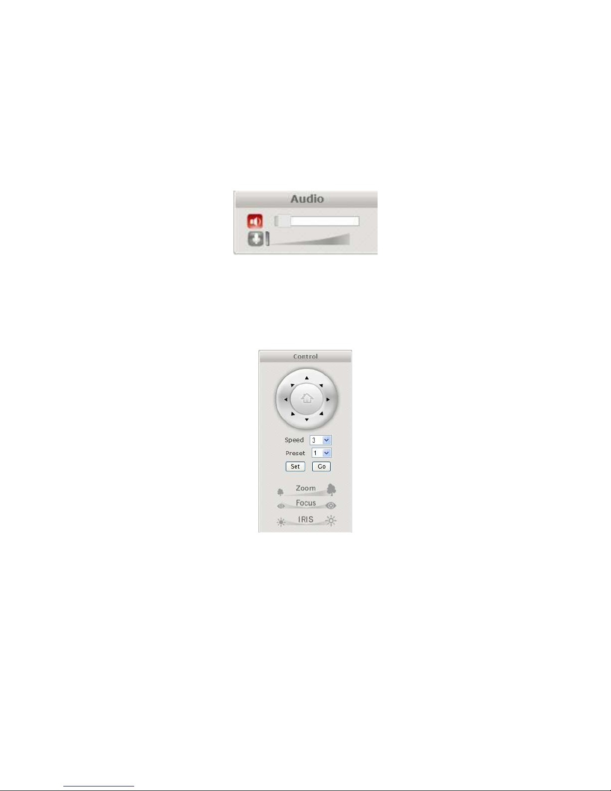
2.6 Audio
Audio volume controls for speaker and microphone. Clicking on the icon will
mute or enable.
2.7 Control (PTZ Control)
The PTZ control panel will not be present in those models where PTZ will not be
used (e.g. EV8580). Use the Set button to mark a preset, and the Go button to use
a preset.
Page 10
6
3 SETUP
The web interface is made up of two main pages: the Live View page and the Setup
page. The Live View page interface was introduced in the previous section.
The Setup interface is primarily used for viewing and configuring the IP camera’s
settings.
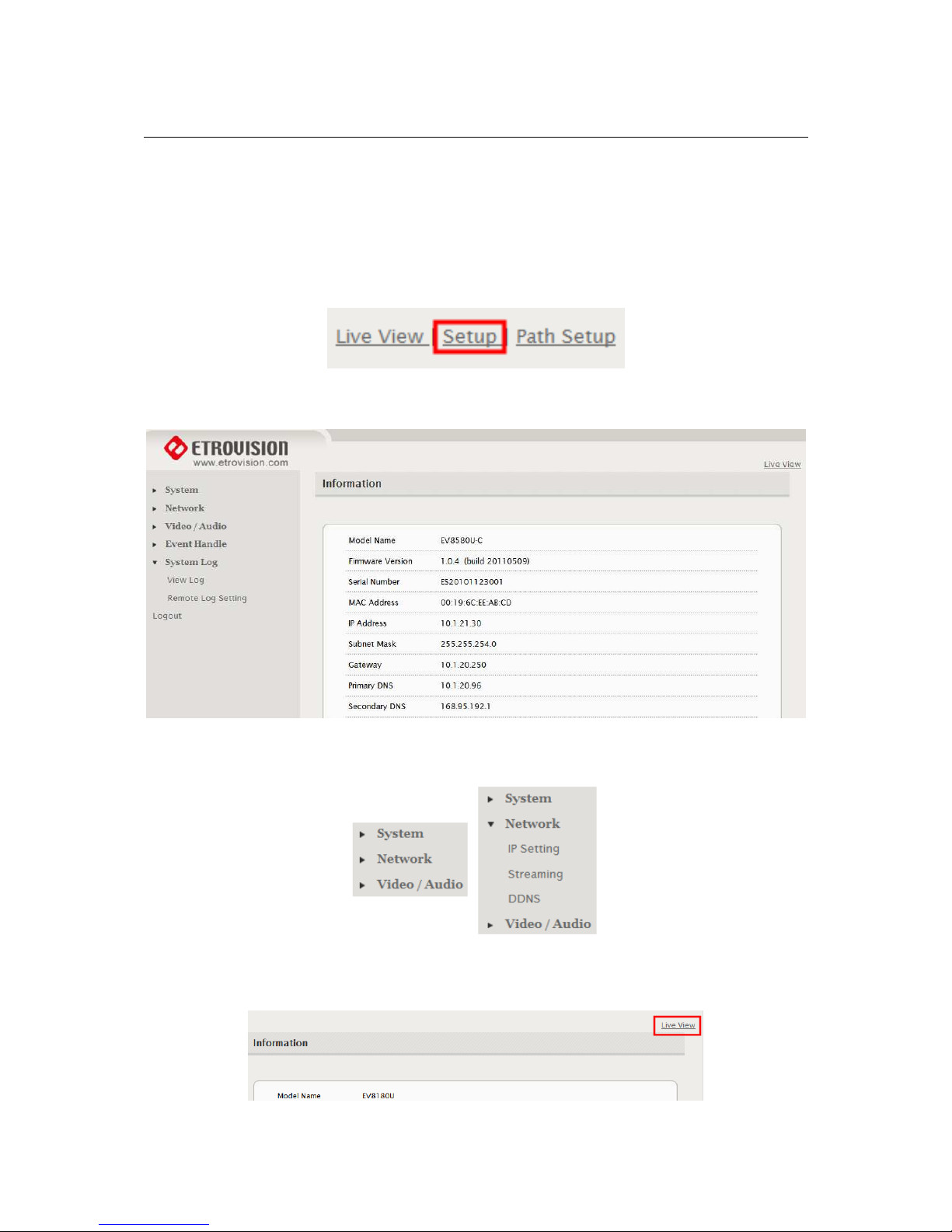
From the Live View page, click the Setup link at the top right side:
Below is a screenshot of the Setup page. The initial page displayed is the “System
Information” page.
The left hand panel lists the configuration nodes which can be viewed and modified.
Clicking on an item will reveal sub menus which are available.
To return to the Live View page, click the Live View link in the right hand corner.
Page 11
7
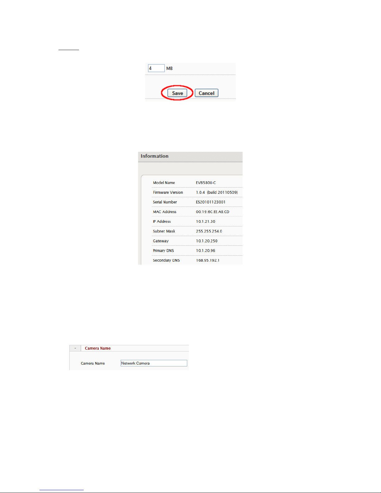
NOTE: Configuration changes in the Setup interface require clicking the SAVE
button. Otherwise, changes will not be applied.
The following discusses the different basic configuration options within the Settings
page.
3.1 System – Information
The Information page is always the initial page displayed when switching to the
Setup view. Basic information related to the IP camera is displayed here.
The page only displays information; no changes can be made here.
3.2 System – Generic Setting
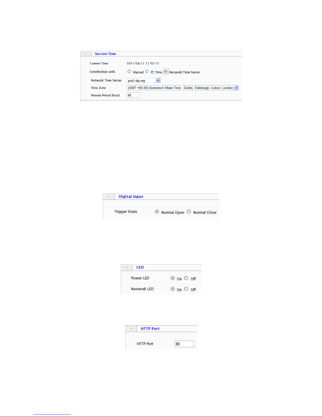
Camera Name
Enter a camera name if a specific name is desired.
Page 12
8
System Time
3 options are available:
• Manual: insert time manually
• PC Time: set to the current PC time
• Network Time Server: periodically synchronizes with a time server
For Network Time Server two standard options are provided. If another time
server is preferred, then choose others from the list and add the address of the
time server which will be used.
Renew Period specifies the synchronization schedule.
Digital Input
This defines the method by which the digital in sensor operates. If the normal
condition is open (N.O.), then the alarm will be triggered when the circuit is
closed. The opposite applies for N.C.
LED
The camera LED lights can be enabled or disabled.
HTTP Port
To use a non-default web server port, change the HTTP Port value.
Page 13
9
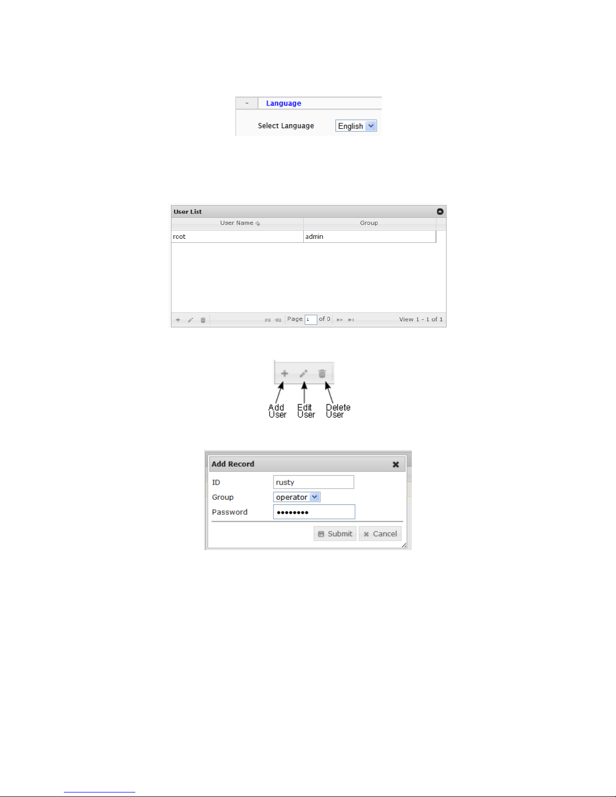
Language
Currently English, Simplified Chinese and Czech are available.
3.3 System – User Account Management
User accounts can be added, edited or deleted via the controls in the left corner.
Users are assigned to a group (admin, operator or viewer).
To edit or delete an account, highlight the account in the User List window and
click the edit/delete button.
After making changes, click SAVE to apply changes.
Page 14
10
3.4 System – Maintenance
Firmware Update
The firmware can be upgraded using the web UI or an SD card. After upgrading,
the ActiveX controls and browser cache should be cleaned to prevent old controls
& pages from being used.
Web UI Firmware Upgrade
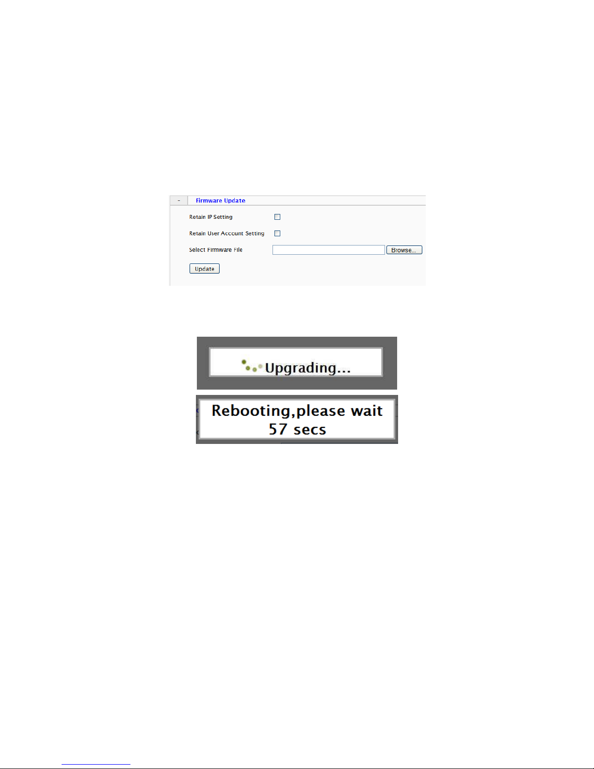
IP and User Account settings can be preserved by checking the appropriate boxes.
After selecting the new firmware file, click Update to proceed. Messages that the
camera is upgrading and rebooting will follow during the upgrade.
Perform the steps in “Clean the ActiveX and IE Cache & History” below, using
Etroscan change the network settings (if applicable), then check the System
Information page to verify the upgrade has been completed successfully.
Upgrade using SD Card
The SD card should be empty of any existing files before proceeding.
1. Rename the firmware file to ev-fw.bin, and copy the file to the SD card.
2. Insert the card into the camera’s SD card slot.
3. Power on the camera, and wait about 1 minute.
The green power LED will flash quickly during the upgrade, become stable
briefly and slowly blink while performing a reboot.
4. Check EtroScan to verify the camera is available (IP address may have
changed to factory default, 192.168.1.2).
5. Remove the SD card.
6. After web UI access is once again available, review the System Information
page to verify the upgrade has completed successfully.
Page 15
11
Clean the ActiveX and IE Cache & History
After upgrading, the ActiveX controls and IE cache & history should be cleared
to prevent old pages and controls from being used.
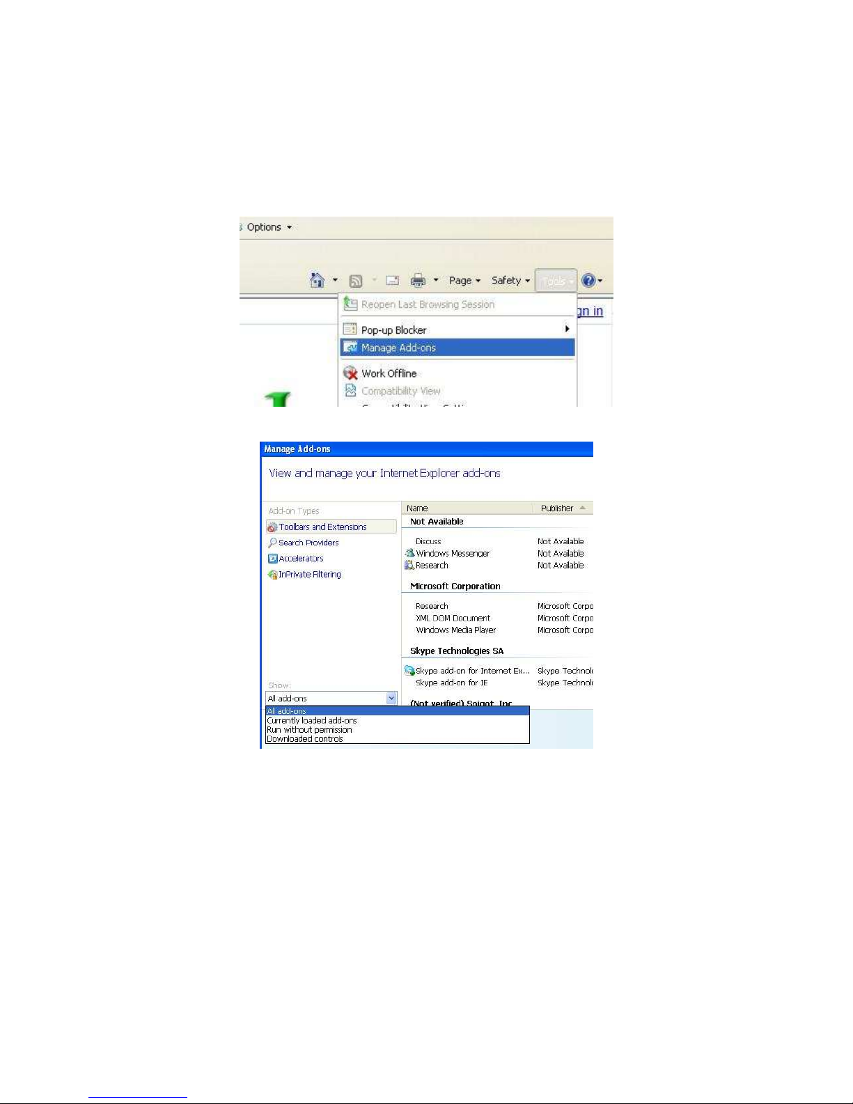
Close all instances of IE and open 1 IE window. In the right corner, select Tools-
>Manage Add-ons
In the Manage Add-ons window, select “All add-ons”
Scroll down and find Etrovision Technology, highlight one of the ActiveX
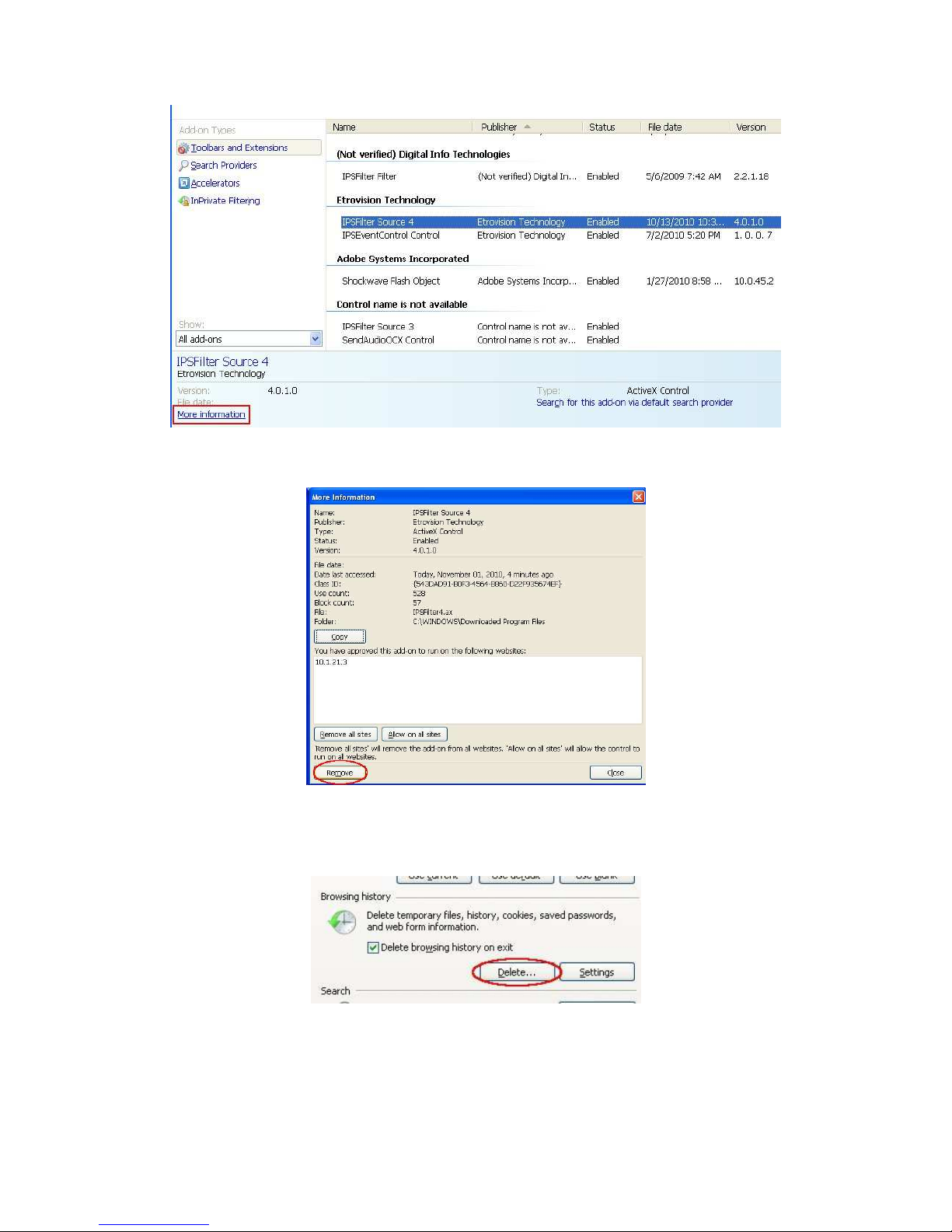
controls, and click the More Information link.
Page 16
12
In the More Information window, click Remove to clear the ActiveX control from
IE.
Repeat this for the remaining Etrovision Technology ActiveX components.
To clear the cache and browsing history, in the IE menu select Tools->Internet
Options. Click the Delete button in Browsing History.
Page 17
13
Export/Import Camera Configuration
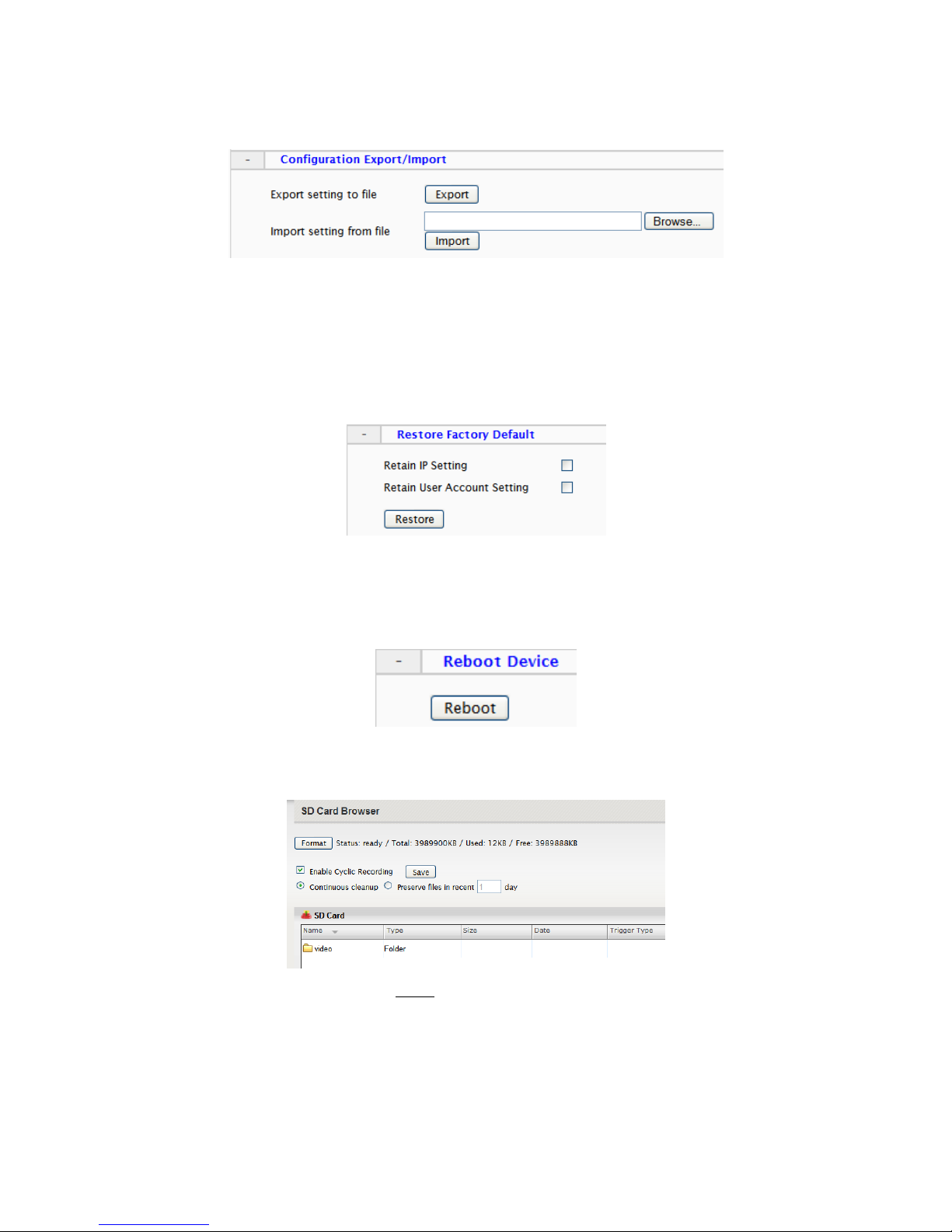
Export will save the camera’s configuration settings to the PC in an archive file.
To import, first use Browse to select a camera’s exported configuration file. Next
click Import to proceed with replacing the current camera settings with the
settings in the configuration file.
Restore Factory Default
Replaces factory default settings via the web UI. Network and/or user account
settings can be saved if the corresponding check boxes are selected.
Reboot Device
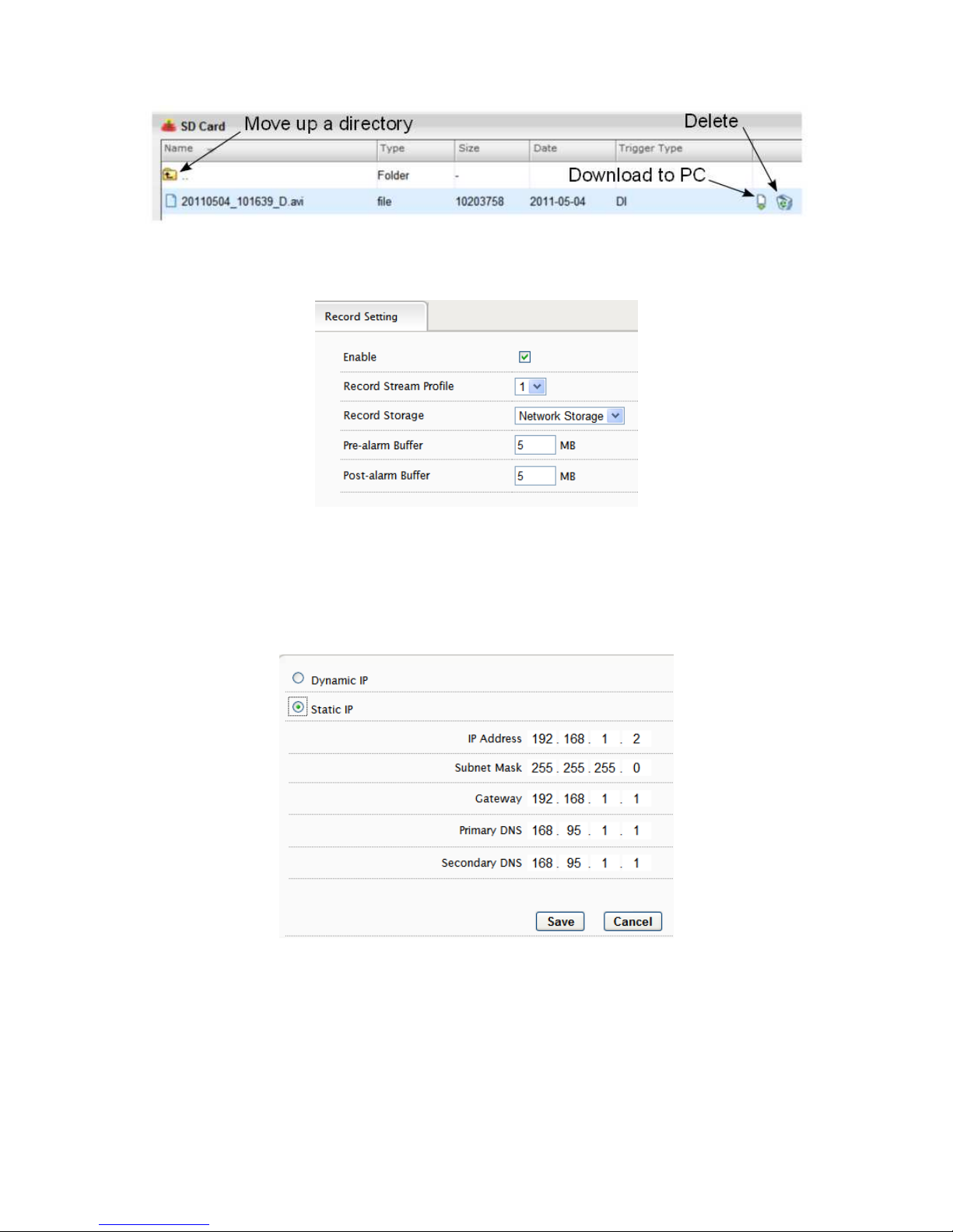
3.5 System – Local Storage
Format will format the card. Note: contents of the SD card will be lost.
Double click on folders to go up/down a directory level.
Page 18
14
3.6 System – Record Setting
When recording is done via event triggers, Record Setting will define how the
recording is performed. Record Stream Profile will only display currently
enabled streams.
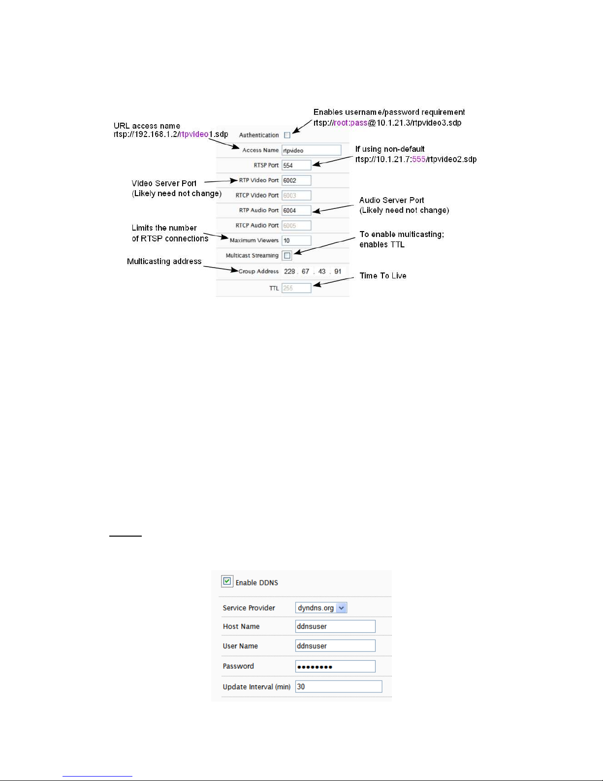
3.7 Network – IP Setting
Select DHCP or Static IP for the camera. If using static, then enter the appropriate
settings for your environment.
Please confirm all network related settings with the network administrator prior
to making any changes.
Page 19
15
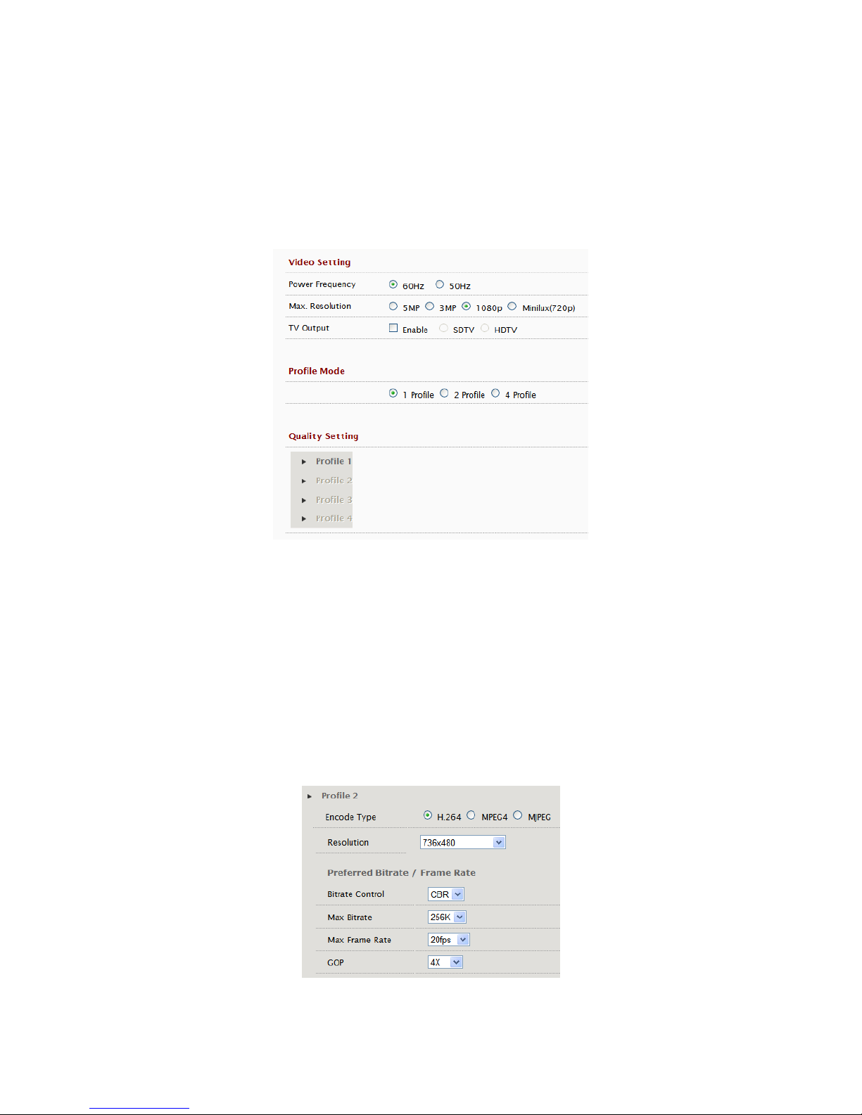
3.8 Network – Streaming
Video and audio server ports only need be changed if a network has security or
operational restrictions using these ports. In most cases, the RTP/RTCP video
and audio should use the default values.
Maximum Viewers refers to concurrent uses. Connections beyond this value will
receive an error upon connection.
Multicasting allows sending a message or data to a group via a single message.
The multicasting parameters are only for configuring a camera to use
multicasting. A networking environment that supports multicasting must be
setup which is beyond the scope of this document.
3.9 Network – DDNS
DDNS is used to map a dynamically assigned IP address (a device using DHCP)
with a hostname.
NOTE: Certain network configuration will likely be required (i.e. mapping the IP
address recognized by the DDNS service to the IP camera) to implement DDNS.
Therefore, the network administrator will likely need to be consulted.
Page 20
16
If the IP camera uses DHCP, a DDNS service can provide a hostname for use
with the IP camera.
Registration with one of the DDNS service providers (ddns.nu, dyndns.org) is
required for use of this feature.
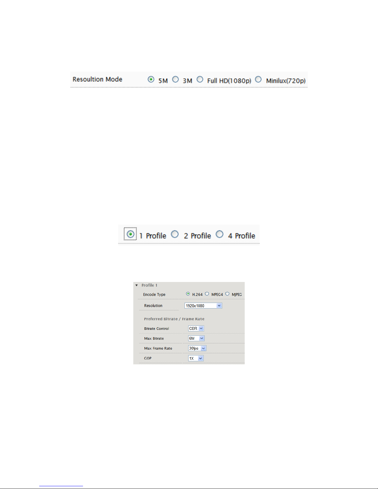
3.10 Video/Audio – Video Setting
Deflicker can be adjusted if flickering is present due to artificial lighting. This
setting should be set to match the utility frequency for a given country.
TV Out Mode
TV Out Mode can be enabled with SDTV or HDTV options available.
• SDTV = CVBS output
• HDTV = YPbPr output
When TV Out Mode has been enabled, 2 video profiles will be enabled. Profile 2
will change to settings which will be used for the video out display (e.g. D1
resolution).
Profile 1 settings will not be modified.
Page 21
17
Resolution Mode (EV8x80F Models Only)
For the F model series, Resolution Mode provides a variety of resolution formats.
5M will change Stream 1 to 5M (2592x1920) with a maximum 10fps for both
Stream 1 and 2.
The 5M option limits ROI to 2, and recording via the camera (e.g. SD card) is
disabled.
Minilux mode uses noise cancelation technology to provide clearer image quality
in low lux conditions.
Profile Setting
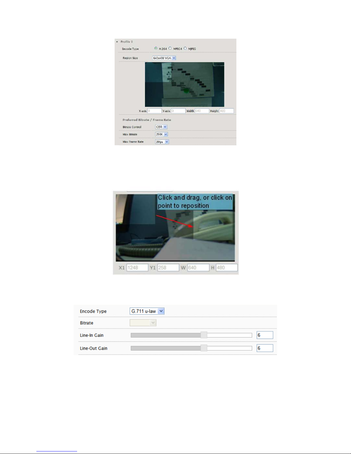
The Video Profile Settings control the ROI (Region of Interest) characteristics. The
ROI video is streamed via RTSP protocol. See the “Streaming ROI” section for
more on viewing ROI video.
The number of available ROI profiles for viewing can be set by selecting the
appropriate option button.
4 Profile defines each stream with a VGA resolution (640x480), while 1 Profile
and 2 Profile settings provide some options for resolution.
Setting for specific ROI profiles can be found in the Video Quality Setting section.
ROI profile 1 & 2 are preconfigured profiles which have some settings that are
configurable (e.g. FPS).
All profiles offer Constant Bit Rate (CBR) or Variable Bit Rate (VBR) mode, and
the GOP (Group Of Pictures) can also be adjusted.
4 Profile defines each stream with a VGA resolution (640x480).
Page 22
18
In the Region Size settings, the image has a mask covering area that will not be
displayed; the lighter shaded area will be what is displayed for the ROI.
To adjust the ROI, click & drag the window or click within the masked area to
reposition.
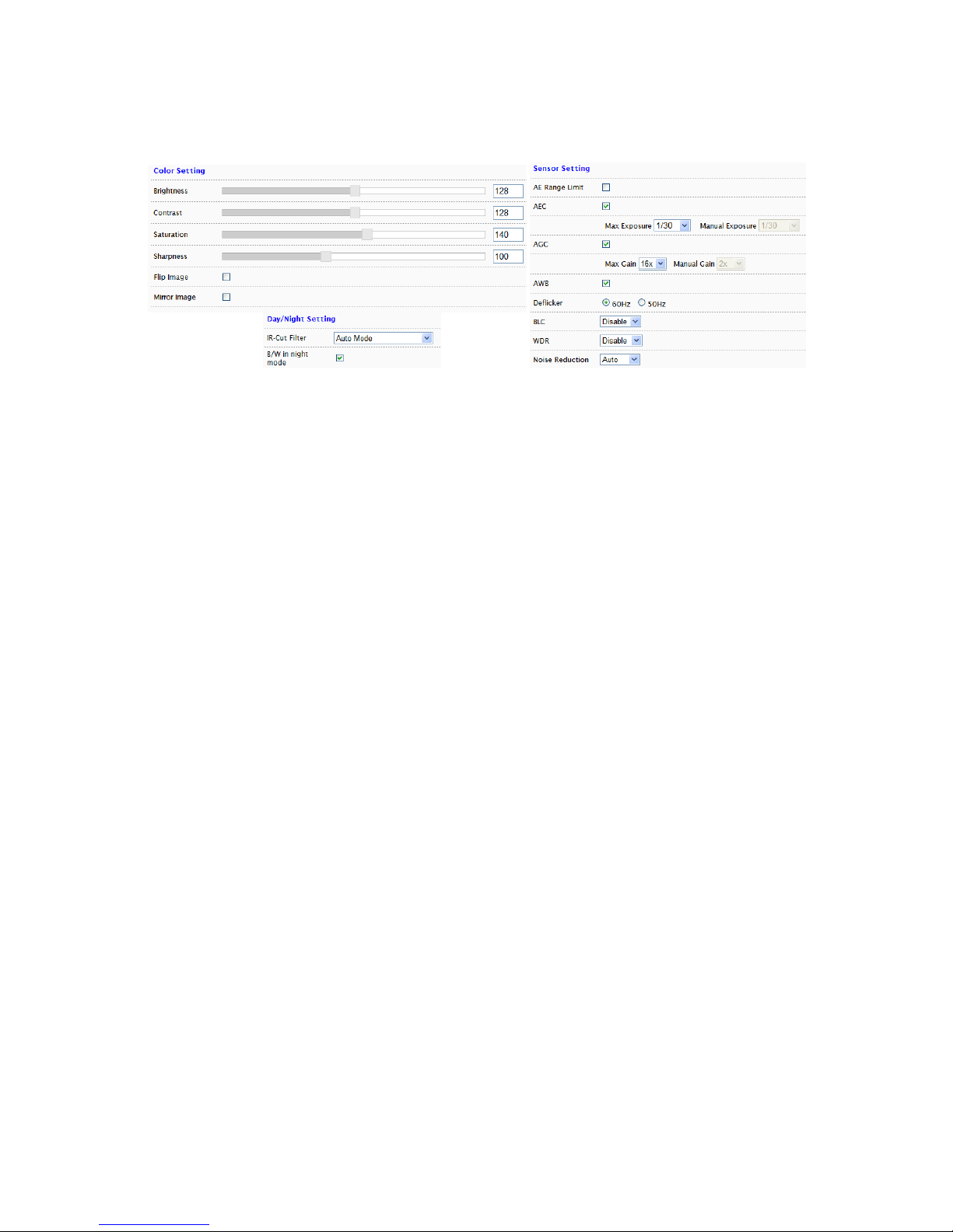
3.11 Video/Audio – Audio Setting
Select the desired audio codec. The Bitrate is configurable for some codecs.
Page 23
19
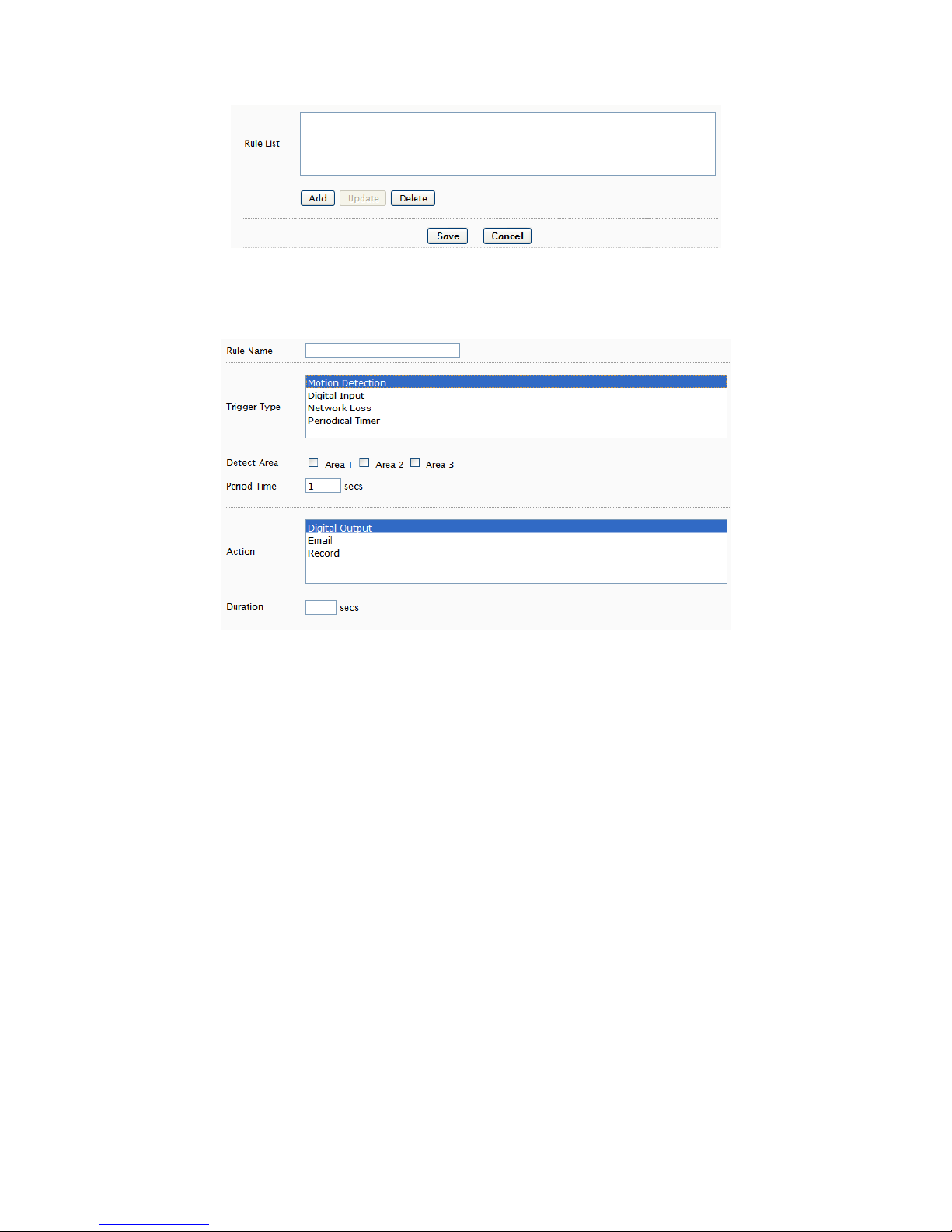
3.12 Video/Audio – Color Setting
• Brightness
• Contrast
• Saturation
• Sharpness
• Flip: flip horizontally (top to bottom)
• Mirror: flip vertically (right to left)
• AE Range Limit: enabling exposes an upper/lower limit list of exposure
values for configuration
Enabling also disables AEC & AGC settings and hides the setting controls
• AEC: Automatic Exposure Control; disabling enables Manual Exposure
Max Exposure: maximum possible exposure time
Manual Exposure: sets specific exposure time
• AGC: Automatic Gain Control; disabling enables Manual Gain
Max Gain: maximum possible gain
Manual Gain: sets specific gain setting
• AWB: Auto White Balance
• Deflicker
• BLC: Back Light Compensation; image EV (Exposure Value) can be increased
to compensate for background lighting
• WDR: Wide Dynamic Range
• Noise Filter: image noise compensation; manual allows user to define level of
noise reduction (0 none; 254 max).
While noise reduction will smooth pixilation (usually in dark areas), too much
may result in blurring.
• IR-Cut Filter: controls IR filter operation
• B/Win night mode: deselect if black & white not desired in night mode
3.13 Event Handle – Event Rule
The Event Rule page is used to define actions (e.g. record to SD card) in response
to the triggering of an event (e.g. motion detection).
Page 24
20
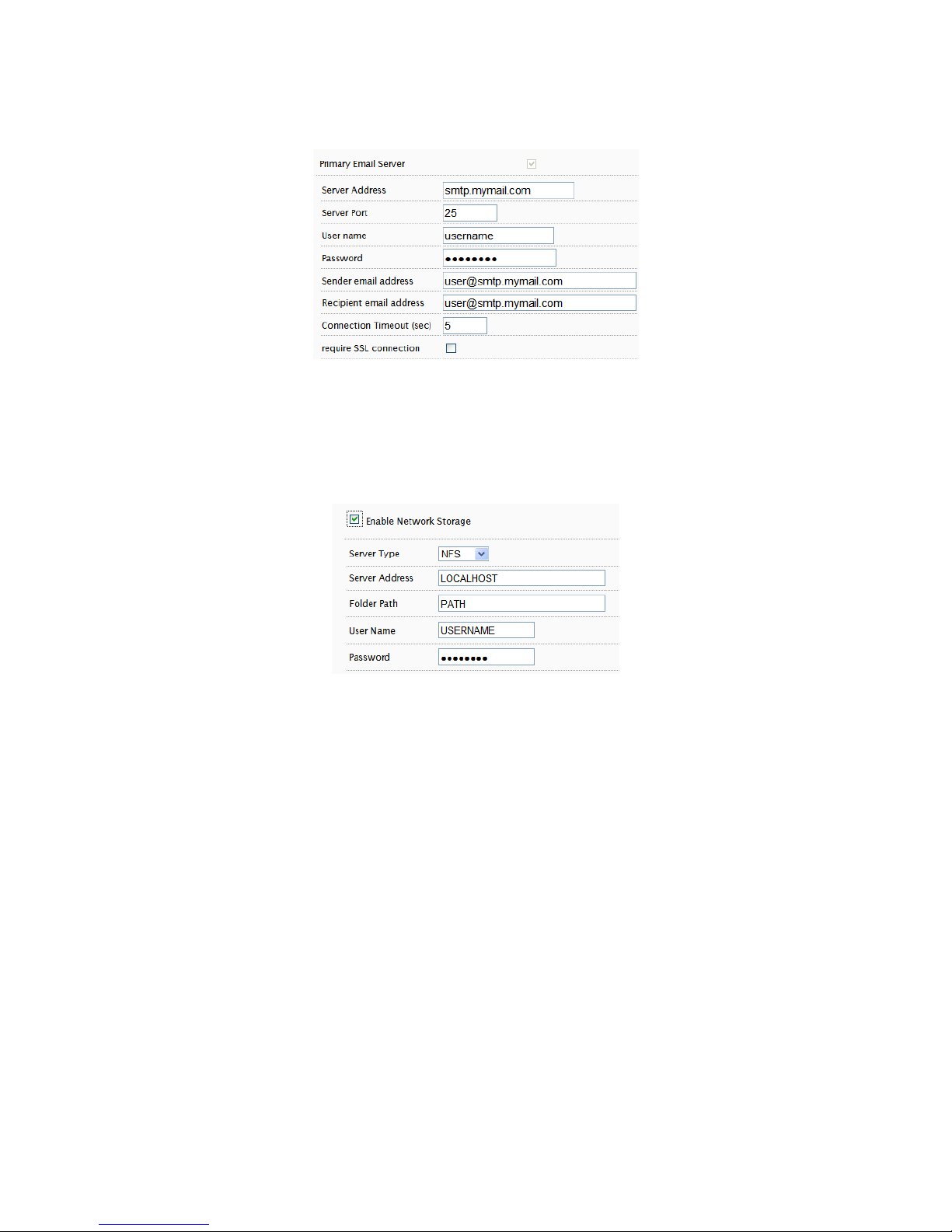
The Add/Update rule screens contain the same fields.
Rule Name is a user defined name for a user defined trigger/action. A trigger or
action may require additional settings (e.g. motion detection area).
Period Time is a time interval during which an event can not be triggered. For
example, if Period Time is set to 60, then after a specific event is triggered (e.g.
motion detection), that event can only be triggered after 60 seconds.
This applies only to a user-defined event. If 2 motion detection events have been
configured (e.g. MD1 and MD2), then if MD1 is triggered, MD2 can still be
triggered regardless of MD1’s Period Time setting.
Be sure to click SAVE in the main Event Rule screen to save any changes.
3.14 Event Handle – Event Server
The Event Server page has configuration options for event notification via email
and event driven video/images to network storage.
Page 25
21
Email Setting
Enter the SMTP server for Server Address and all additional relevant details.
The username may only contain alphanumeric characters and the underscore
character, “_”.
Network Storage
NFS and Samba are supported; if enabled then input relevant details.
3.15 Event Handle – Motion Detection
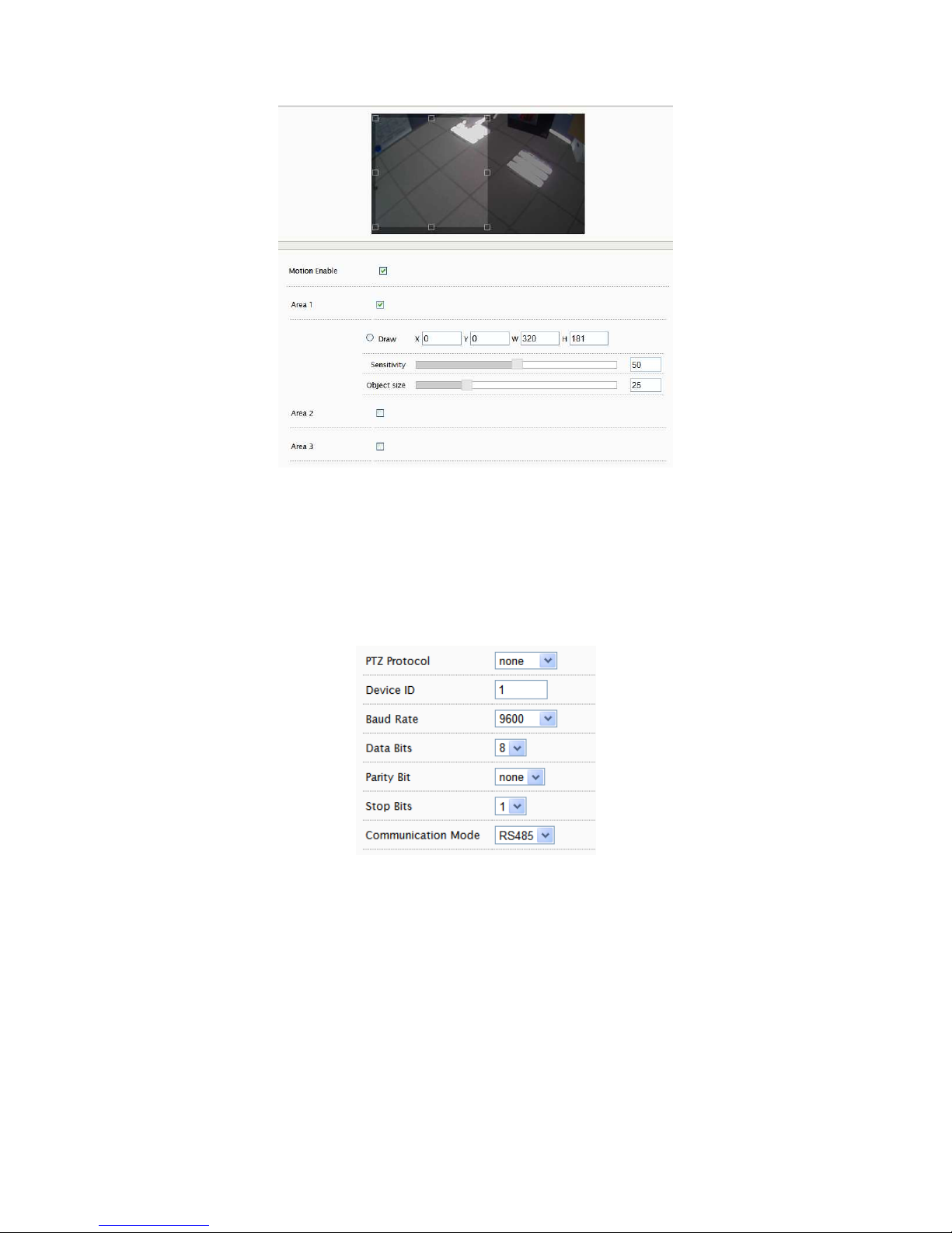
To use motion detection, motion detection should be enabled and at least one
motion detection area enabled. Checking the box for an Area (e.g. Area 1) enables
it.
Page 26
22
To modify a Detect Area, select “Draw” and click & drag to resize the detection
area (light area) or specify coordinates (X, Y, W, H). X=horizontal, Y=vertical,
W=width, H=height.
3.16 PTZ Control – Serial Setting
PTZ settings can be applied if the camera will interact with a PTZ device.
Pelco P and D are supported as well as RS-485 and RS-422 communication modes.
Please refer to the PTZ device’s required settings to configure the web UI PTZ
settings.
3.17 System Log – View Log
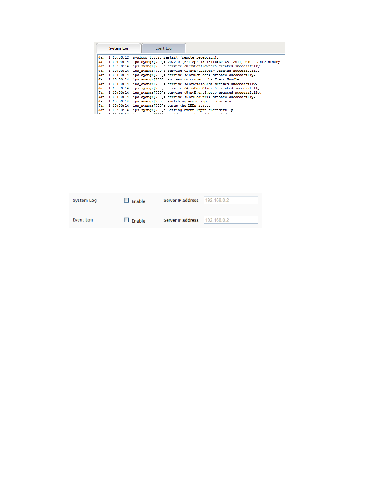
The System Log displays system and event details.
Page 27
23
The System Log has information specifically related to basic system messages (e.g.
startup, shutdown) while the Event Log contains information related to events
triggered.
3.18 System Log – Remote Log Setting
The System and/or Event log data can also be remotely logged. Check the box to
enable and provide the corresponding log server address.
Page 28
24
4 STREAMING VIDEO
Video can be streamed to a video player (e.g. VLC) via RTSP protocol using the
standard RTSP port number 554.
The URL is in the following format:
rtsp://[IP ADDRESS]/rtpvideo[1-4 or 1-8].sdp
Replace with the appropriate IP address.
rtpvideo1-4 represent video profiles with different characteristics. For more
information on video profiles, see Video/Audio – Video Setting”.
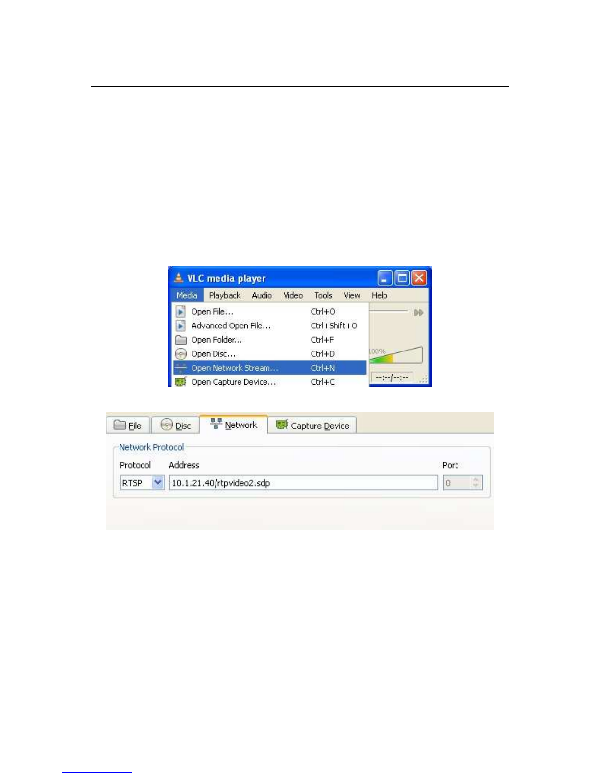
Using VLC for example, select Media from the menu bar and Open Network
Stream.
Next specify IP address of the camera and stream profile.
Click Play and video will begin streaming in the video player.
WARNING: firewalls and other network security may prevent video streaming.
Authentication
If Streaming authentication has been enabled in Network -> Streaming
Then a username/password must be supplied with the RTSP URL
rtsp://USERNAME:PASSWORD@[IP ADDRESS]/rtpvideo[1-4].sdp
Page 29

25
Page 30
26
5 ADDING A CAMERA TO AN NVR
The following gives some basic guidance for adding EV8x8x cameras to an NVR
system that supports RTSP streaming. Please refer to the NVR instructions for
specific details on how to add and administer cameras for the NVR system.
When adding a camera to an NVR, the NVR will likely require 3 configuration
parameters from the camera:
• An RTSP URL
• An HTTP Port Number
• The administrator username and password
5.1 RTSP URL
The RTSP URL will likely be the Profile 1 stream from the camera which by
default will be in the following format:
rtsp://[IP ADDRESS]/rtpvideo1.sdp
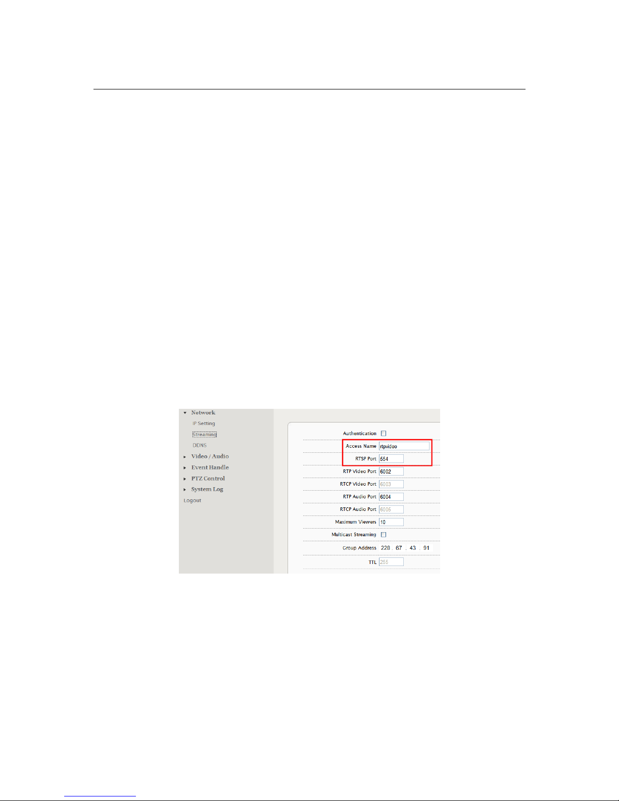
This assumes that the default port, 554, is being used, the “rtpvideo” access name
is defined, and camera profile stream 1 is being used.
Below is the Stream Setting page which defines the RTSP port and the Access
Name.
If the Access Name and/or RTSP Port have been changed, then specify the RTSP
URL in the following format:
rtsp://[IP ADDRESS]:[PORT#]/[ACESSNAME]1.sdp
example: rtsp://10.1.21.138:555/ev1.sdp
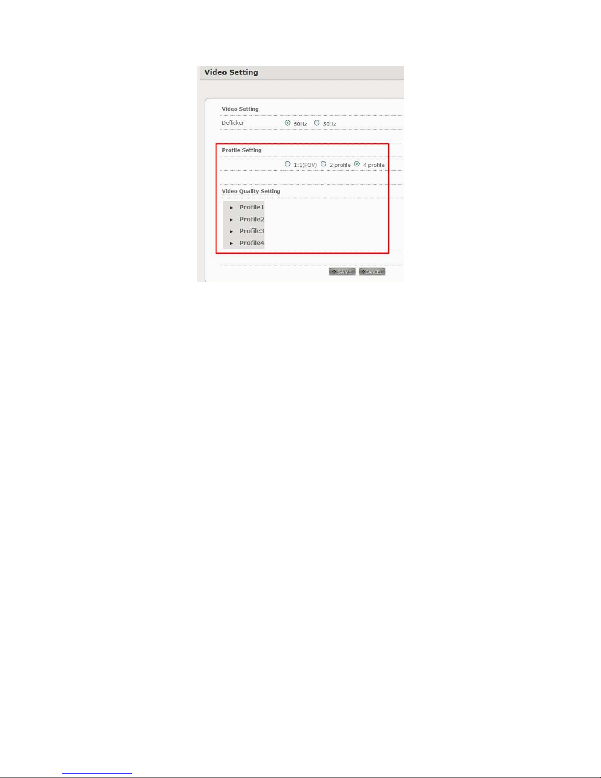
The camera can be configured with multiple independent streams. The Video
Settings page lists information related to the different profile streams.
Page 31
27
To assign a specific profile stream to the NVR, then append the appropriate
profile number to the access name:
rtsp://[IP ADDRESS]/[ACCESSNAME][PROFILE#].sdp
example: rtsp://10.1.21.38/rtpvideo3.sdp
5.2 Administrator User & Password
The administrator username is “root” and the default password is “pass”.
Page 32
28
6 FIREFOX & CHROME
While there is support for both Firefox and Chrome, the Live View interface will not
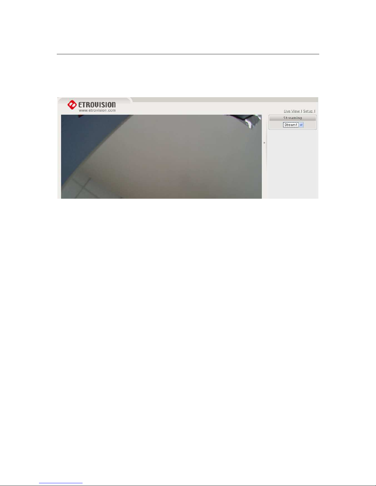
have many of the controls available in IE. These controls are implemented using
ActiveX which is only supported by IE.
 Loading...