

Page 1

EV8180 Series
Installation Manual
EV8180F/EV8180U
Document Version 0.2
Page 2

About This Guide
The Installation Manual provides instructions for the initial setup & configuration of:
• EV8180U
• EV8180F
Before Using the IP Camera/Video Server
Check the PC requirements
Review the OS platform requirements
Read an special and import precautionary information
Having basic knowledge of network setup and configuration will be helpful
Disclaimer
© 2010 Etrovision Technology. All rights reserved.
EtroLink™ & AnyUSB™ are trademarks of Etrovision Technology; other product or
service names mentioned herein are the trademarks of their respective owners.
Information contained in this document may be superseded by updates. No
representation or warranty is given and no liability is assumed by Etrovision
Technology with respect to the accuracy or use of the information, or infringement of
patents or other intellectual property rights. No licenses are conveyed, implicitly or
otherwise, under any intellectual property rights.
Page 3

1 INTRODUCTION..............................................................................1
1.1 Dual Streaming Capabilities........................................................................ 1
1.2 Package Checklist.......................................................................................1
1.3 Frontal Camera View...................................................................................1
1.4 Rear Camera View......................................................................................2
1.5 I/O Cable..................................................................................................... 2
2 INITIAL CONFIGURATION...............................................................4
2.1 Initial Requirements.....................................................................................4
Software Requirements...............................................................................4
Install EtroScan™........................................................................................4
2.2 Physical IP Camera Connections................................................................4
Connect to the Network...............................................................................4
Connect I/O Cable.......................................................................................4
Connect Audio In/Out..................................................................................4
Power on IP Camera...................................................................................5
2.3 Initial Network Configuration ....................................................................... 5
Factory IP Address......................................................................................5
Using EtroScan™........................................................................................5
Change Network Setting via EtroScan™.....................................................7
2.4 Access IP Camera Web Interface ............................................................... 9
3 RESTORE FACTORY DEFAULT SETTINGS.................................11
Page 4
1
1 INTRODUCTION
This guide is for the use with firmware version 0.1.2.
Please pay close attention to areas that are highlighted in YELLOW. These areas
highlight special instructions for this firmware release or functionality that is not yet
available.
1.1 Dual Streaming Capabilities
Cameras support dual streams simultaneously in pre-stage firmware Include:
Stream1
Stream2
Bit Rate Frame size and
Frame rate
Stream1 H.264
Max : 12Mbps 1080P, up to 25fps
Stream2 MJPEG
Max : 8Mbps VGA, up to 15fps
NOTE: If there are more than 2 concurrent users, the image may be unable to
achieve real-time performance. This is a system limitation.
1.2 Package Checklist
The packaging will include the following materials.
• IP Camera x 1
• Power Adapter x 1
• I/O cable x 1
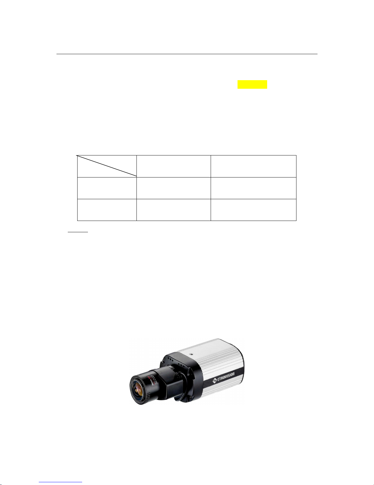
1.3 Frontal Camera View
Page 5
2
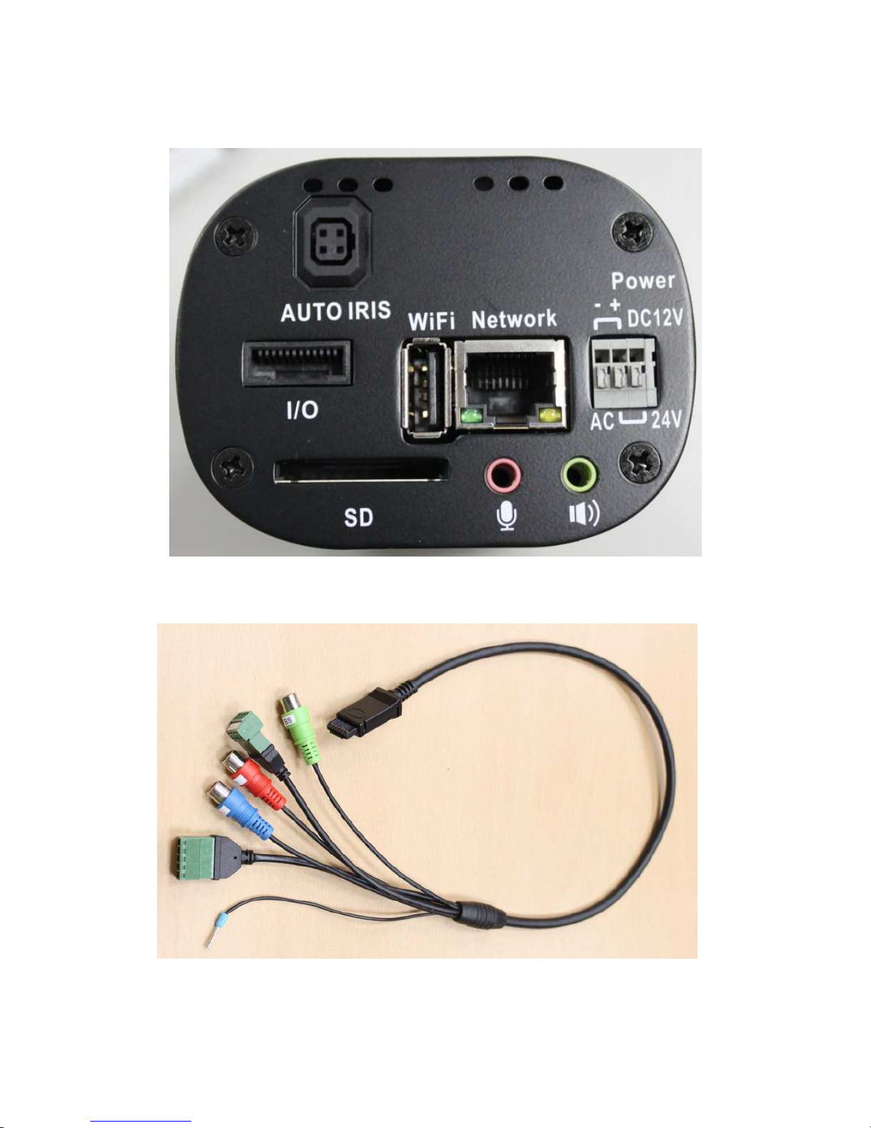
1.4 Rear Camera View
1.5 I/O Cable
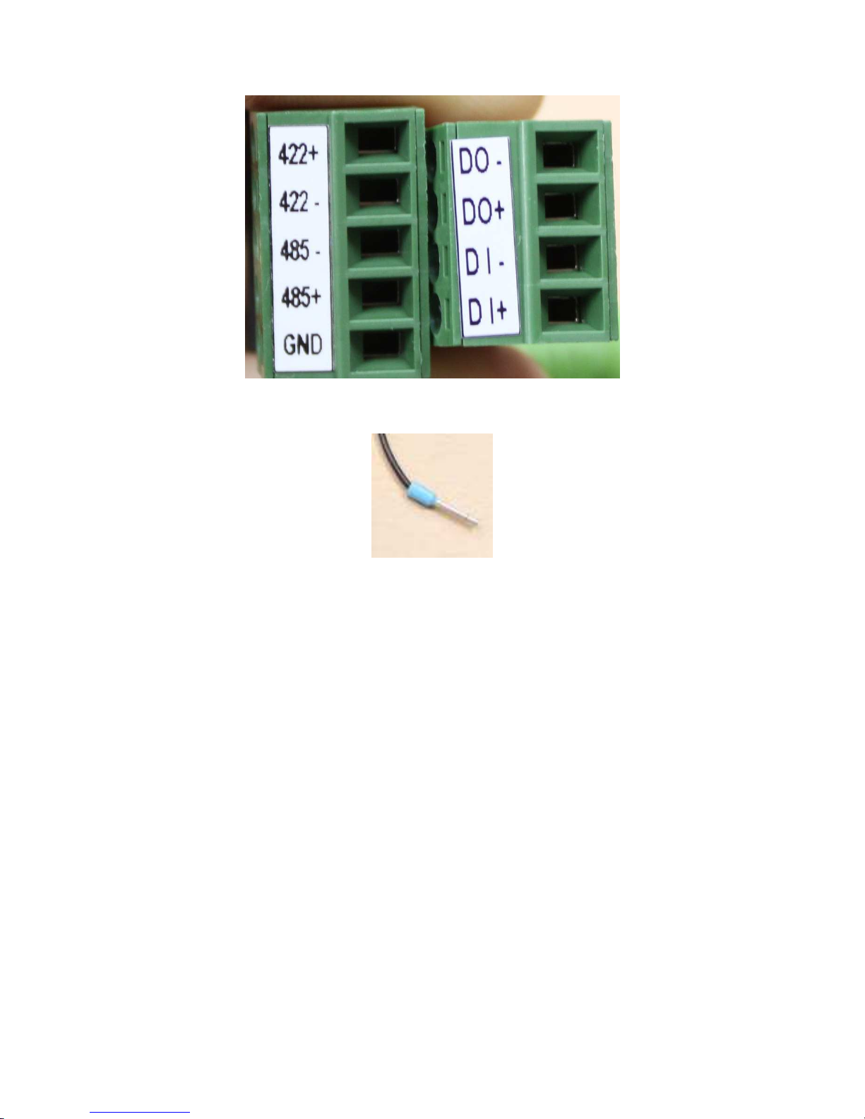
The blue, red and green plugs are HDTV video out connectors.
The two block terminals are digital I/O and RS-485/422 connectors.
Page 6
3
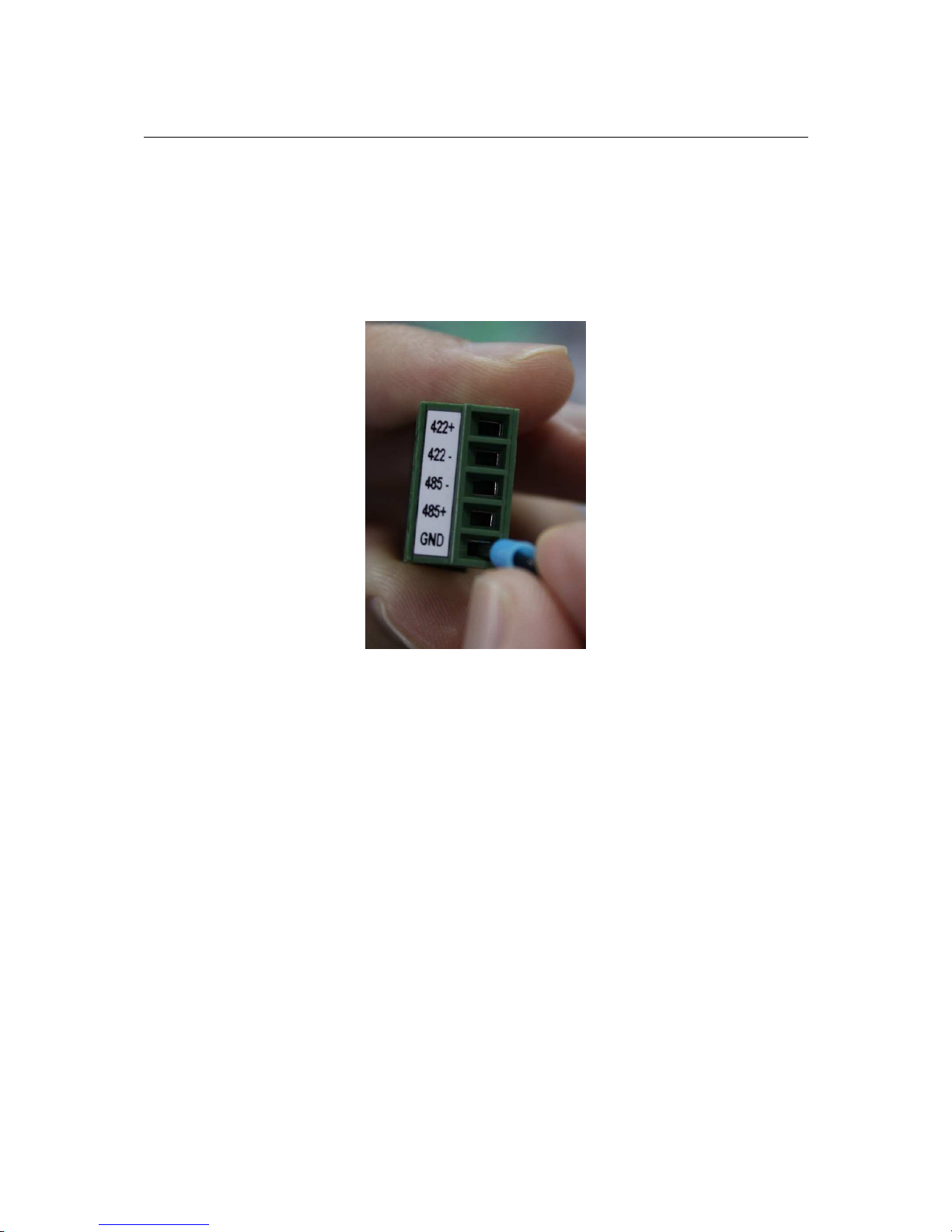
The GND port is also used for restoring factory default settings using the blue
metal pin which serves is used specifically for restoring factory default settings.
Page 7

4
2 INITIAL CONFIGURATION
2.1 Initial Requirements
Software Requirements
Installation and configuration require the following:
• Microsoft Windows 2000 or XP Operating System
• Microsoft Internet Explorer version 6 or higher
NOTE: Other browsers (i.e. Mozilla Firefox) are not currently supported.
Install EtroScan™
EtroScan™ is a utility is used to configure network settings for IP cameras and
other devices (i.e. NVR). EtroScan™ is available via two methods.
EtroScan™ can also be downloaded from Etrovision’s website. It is available in
the Software Tools section of the Download area,
http://www.etrovision.com/Download_list.aspx?no=5.
After downloading the archived file, extract the contents and run Setup.exe to
install EtroScan.
2.2 Physical IP Camera Connections
Connect to the Network
Connect the camera to network hub/switch via a standard CAT5 Ethernet cable
with an RJ-45 connector. Please note that the PC must be on the same network
domain as the IP camera.
NOTE: Please use a gigabit Ethernet switch for high bit rate streaming.
Connect I/O Cable
Currently not supported in firmware version 0.1.2.
Connect Audio In/Out
For audio functionality, connect the audio input cable.
NOTE: Video flicker may occur when enabling/disenabling audio. This situation
normally only lasts for a second.
Page 8
5
Power on IP Camera
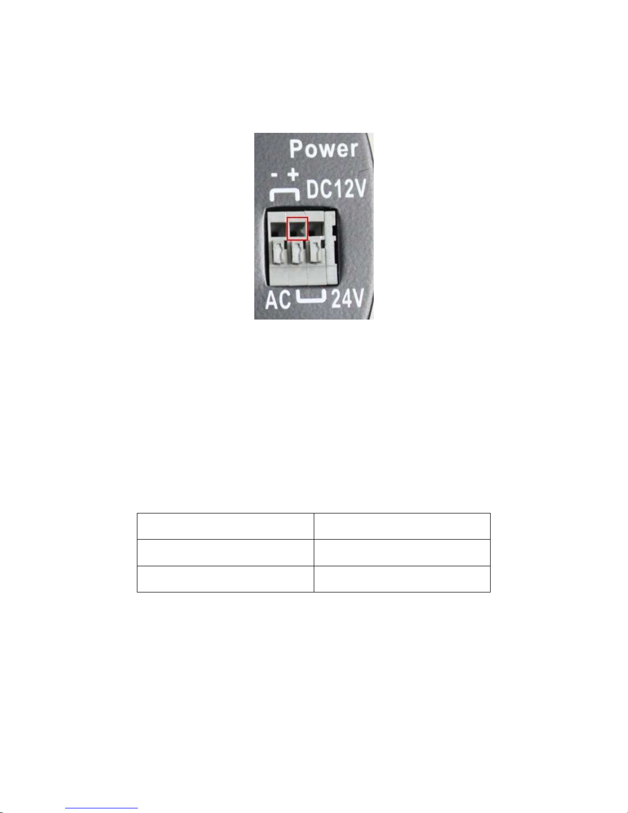
The positive and negative lines need to be connected. The middle port (outline in
red) is the positive.
The left and right are negative, and depend on if using DC12V or AC24V adapter.
Connect the power adapter to the power connector. The adapter should be
connected to 110v~22OV AC socket. There is no power button on the camera, so
connecting/disconnecting the power adapter will start/shutdown the IP camera.
2.3 Initial Network Configuration
To configure the IP camera’s network settings use the EtroScan™ utility.
Factory IP Address
Below are the initial factory IP address settings for the IP camera:
IP Address 192.168.1.2
Subnet Mask 255.255.255.0
Gateway 192.168.1.1
Using EtroScan™
EtroScan™ allows users to easily find an IP camera and configure the settings.
Page 9
6
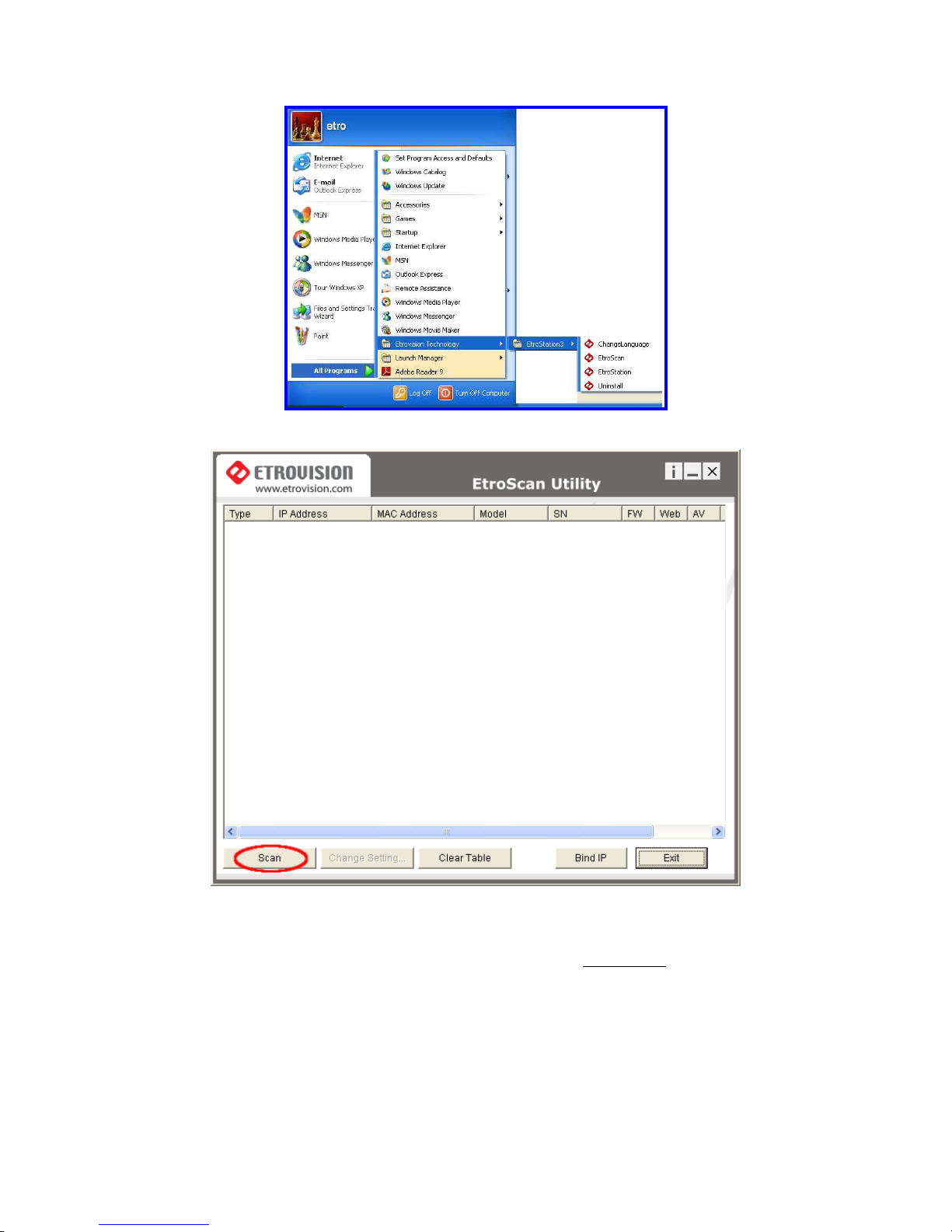
Select EtroScan™ from the start menu to start.
Press the Scan button to list the IP and MAC address list for IP cameras on the
network.
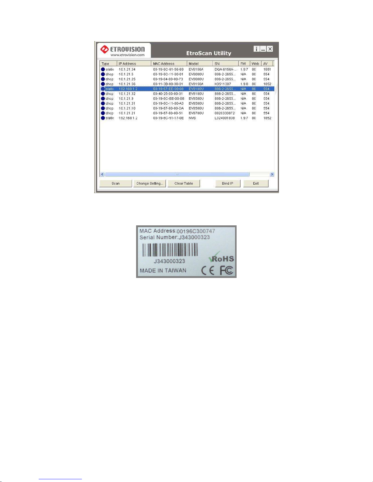
A new IP camera will display the factory IP address, 192.168.1.2. However, if
multiple new devices are present on the network, then multiple instances of
192.168.1.2 will be listed.
Page 10
7
To identify a specific IP camera, use the MAC address which is located on the
bottom of the camera. Below is an example of the label displaying the MAC
address.
Change Network Setting via EtroScan™
There are two ways to modify the network settings.
Page 11
8
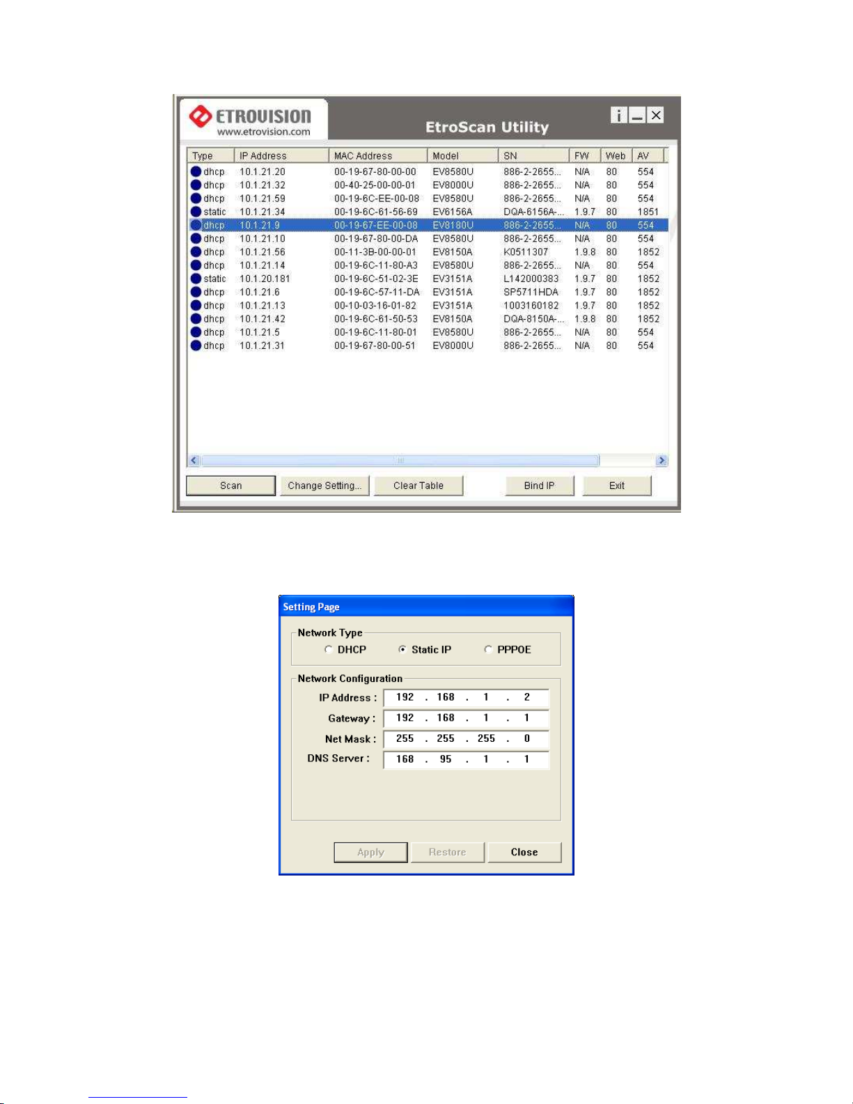
1. Double click on a specific IP address; the setting page will be displayed.
2. Click Change Setting… button at the bottom of the screen.
Either method will display the network settings configuration.
Here a static IP address can be specified or the device can be changed to DHCP.
A login is required to complete.
Page 12
9
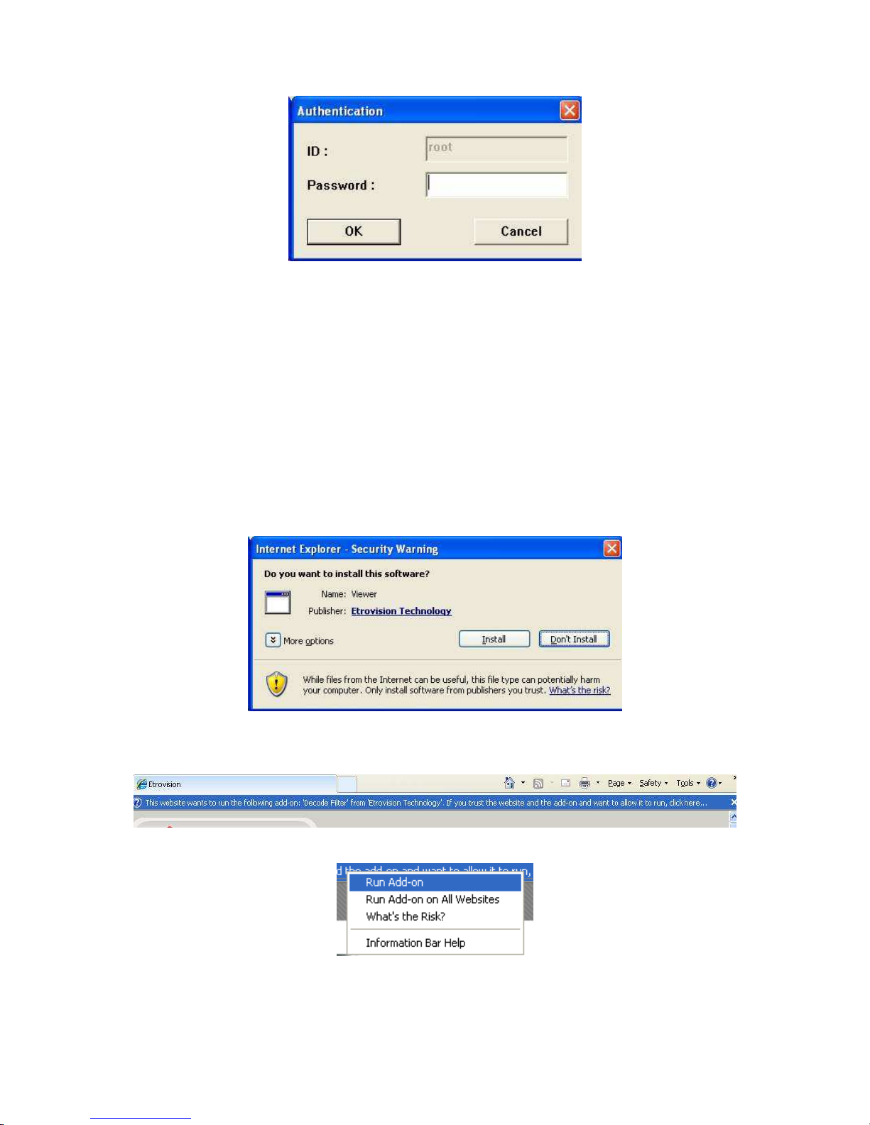
Enter pass for the root password.
2.4 Access IP Camera Web Interface
MS Internet Explorer is used to access and configure the IP camera. When
accessing an IP camera using the web interface for the first time (or when the IP
address changes), some configuration for ActiveX controls may be required.
These controls are necessary for proper operation of the web UI.
1. Open an IE browser
2. Type in the IP address of the IP camera.
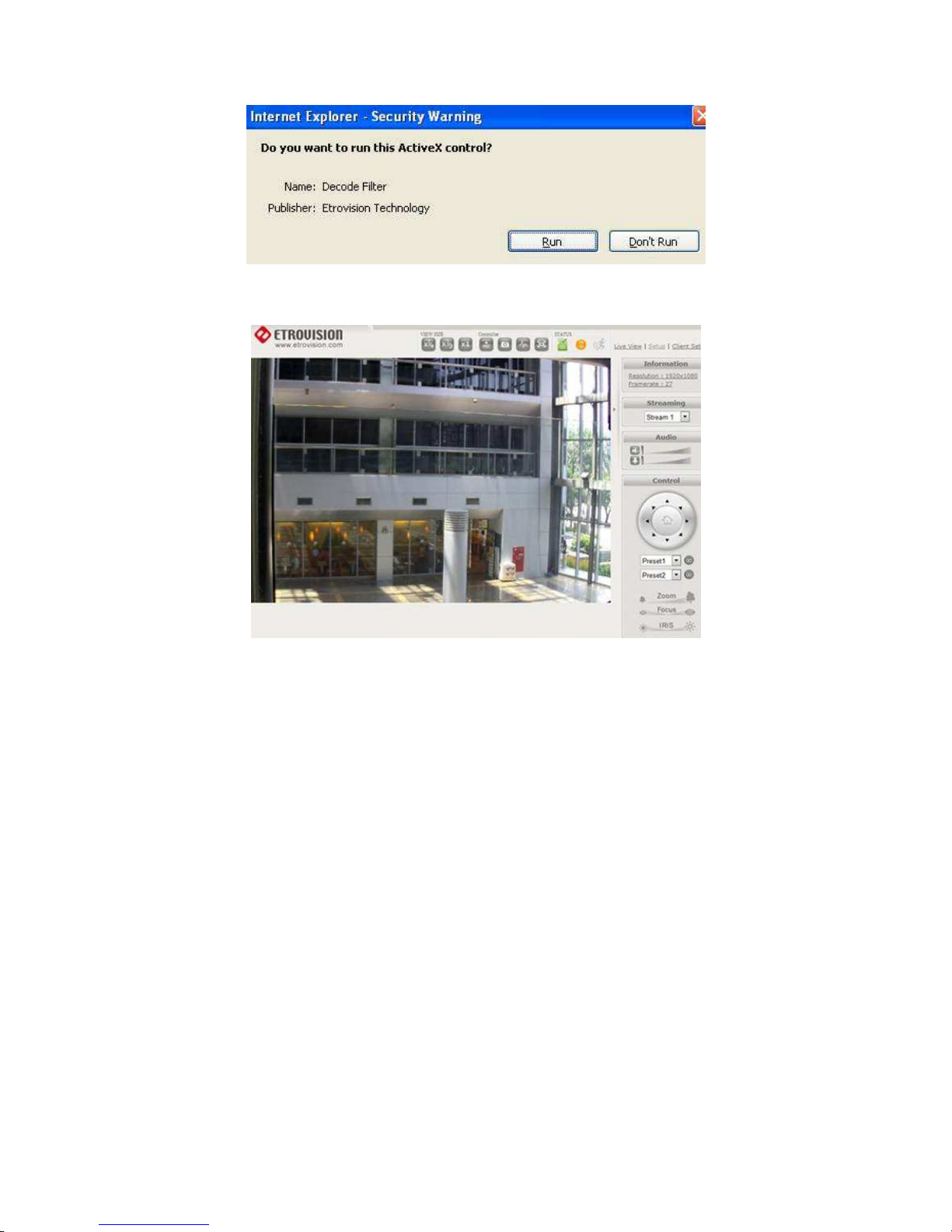
At this point the browser will likely display pop-up windows and messages in
the browser border to download/active certain Active X controls.
Click Install or Run for any pop-up windows.
Near the top of the browser, there will likely be additional messages.
Click on the add-on message, and choose Run Add-on
Page 13
10
Repeat the above until all ActiveX controls have been initiated. Once the process
is complete, the Live View will be displayed.
Page 14
11
3 RESTORE FACTORY DEFAULT SETTINGS
If necessary (e.g. missing root password), the factory default settings can be restored.
1. Power on the camera
2. Wait for the camera to boot up (if there is some problem with the firmware which
prevents the camera from booting properly, then skip this step)
3. Insert the factory default metal pin into the GND slot of the RS-485/RS-422 cable
for about 5-10 seconds
4. Remove the pin and the camera will then reboot with the factory default settings
NOTE: default factory settings will reapply the 192.168.1.2 IP address, and the root
password will be pass.
 Loading...