

Page 1

EV6552A Series
Fixed Dome IP Camera
User’s Manual Ver. 6.1
Page 2
About This Guide
Model
EV6552A
EV6552AP
Before Using the EV6552A & EV6552AP Fixed Dome IP Camera
Check PC requirement
Check OS platform requirement
Install EtroStation™ 3.0 software before you start using the video
server.
Read special and important precautionary information.
Basic knowledge of network setup and configuration will be helpful.
Icon Descriptions
Notes: This icon represents a tip for operation.
Caution: This icon stands for an action that probably impairs the
operation.
Warning: This icon stands for an action that can cause damage to the
operation.
Disclaimer
© 2007 Etrovision Technology. All rights reserved.
Etrolink™ & AnyUSB™ are trademarks of Etrovision Technology; other
product or service names mentioned herein are the trademarks of their
respective owners. Information contained in this document may be
superseded by updates. No representation or warranty is given and no
liability is assumed by Etrovision Technology with respect to the accuracy or
use of the information, or infringement of patents or other intellectual
property rights. No licenses are conveyed, implicitly or otherwise, under any
intellectual property rights.
Page 3

TABLE OF CONTENTS
Enter the port number, user name, password, and server name information of the
SMTP server. If you’d like to receive the attached snapshots, please enable the
appropriate check box. Authentication is not a mandatory requirement by SMTP
servers. In some situations, the required information includes the SMTP server
name and e-mail address only. ................................................................... 36
Please fill in the address of remote FTP server, port number, user name, and
password. ............................................................................................... 37
Page 4
1. PRODUCT OVERVIEW
EV6552A & EV6552AP support dual streams simultaneously.
Combination options include:
Stream 1 Stream 2
H.264 M-JPEG
H.264 MPEG-4
H.264 H.264
M-JPEG MPEG-4
M-JPEG H.264
M-JPEG M-JPEG
MPEG-4 H.264
MPEG-4 M-JPEG
MPEG-4 MPEG-4
Stream 1 Stream 2
Note: If users assign MPEG-4 for both Stream1 and 2, the image will be unable
to reach real-time performance. M-JPEG for both Stream 1 and 2 leads to the same
result. This is system limitation.
Difference between EV6552A and EV6552AP:
Features
EV6552A EV6552AP
Sensor type
1/4” Low-light sensitive CMOS
Compression Format
M-JPEG, MPEG-4 dual codec
Audio
Line Out x 1
Scanning System
progressive scan
Page 5
PoE
N/A YES
Package Checklist
EV6552A IP Camera x 1
Power Adapter x 1
USB Cable x 1
Product CD x 1
Screws
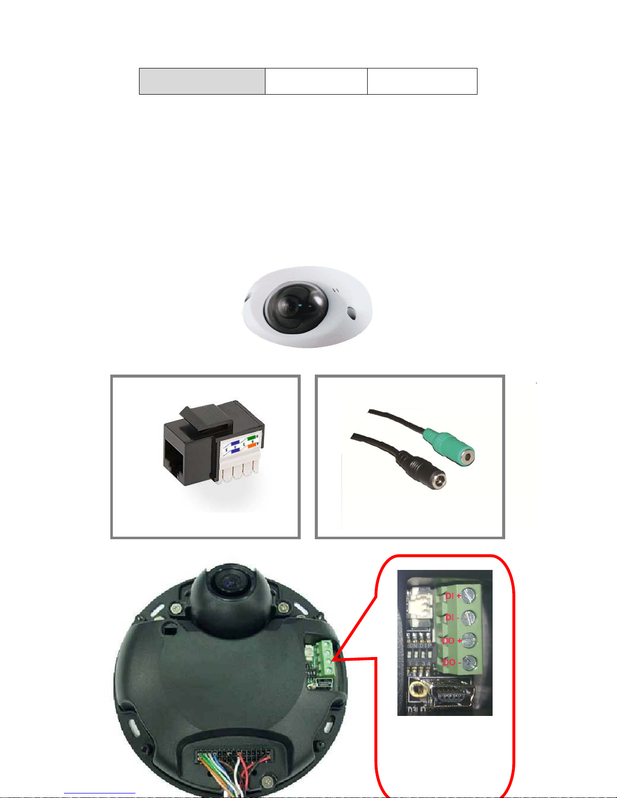
Front
Connectors
DIP SW Pin#1: AES On/Off
DIP SW Pin#2: AGC On/Off
DIP SW Pin#3: AWB On/Off
DIP SW Pin#4: Mirror On/Of
f
RJ-45 Ethernet Connect
Green: Audio Out Cable
Black: Power In Cable
Page 6
2. SETTING AND INSTALLATION
Note:
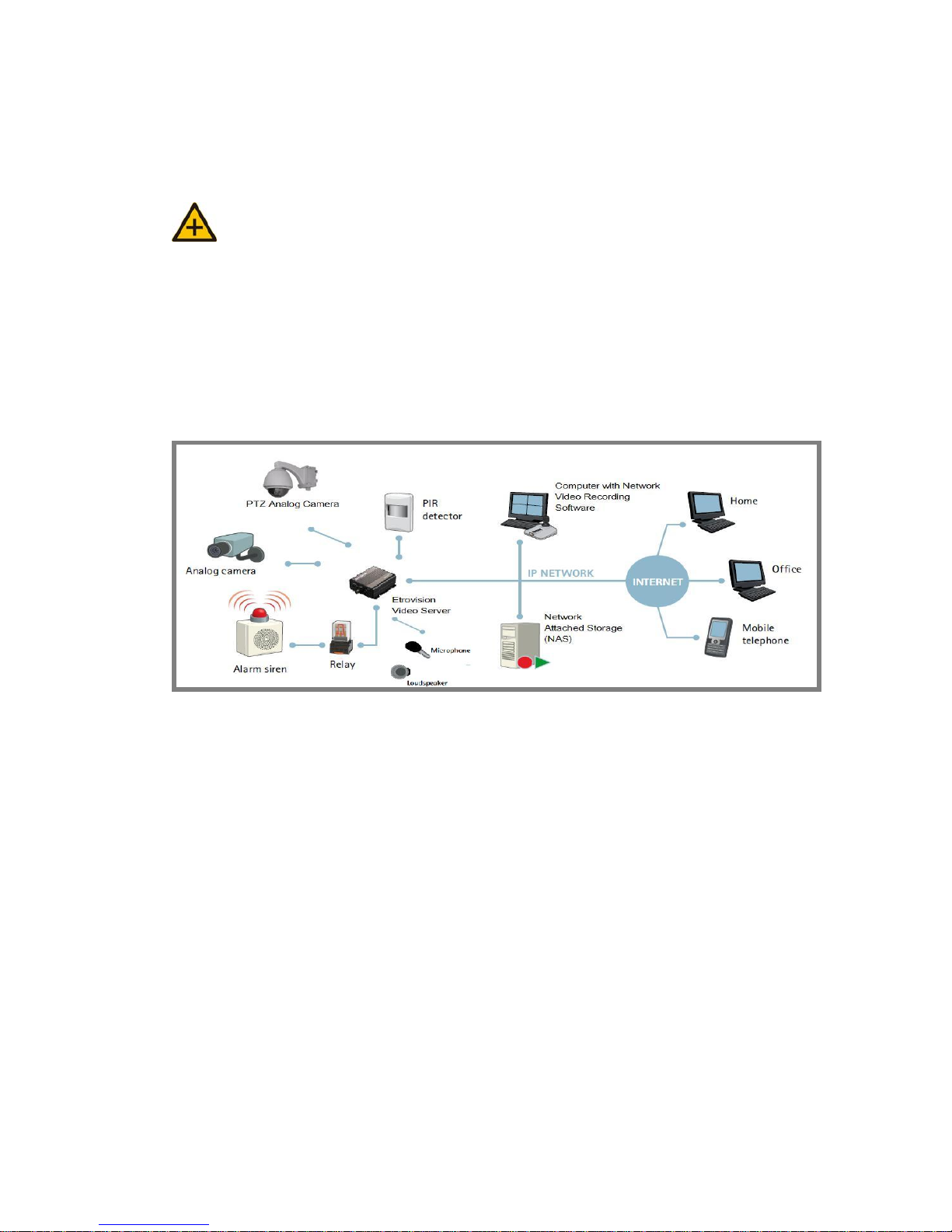
Connect EV6552A / EV6552AP to your network by using a standard Cat-5
cable.
Connect the video output of your camera with video in of video server, using
standard 75Ω coaxial cable with BNC type connector.
Connect speaker and active microphone to Audio In / Out.
Product CD
Product CD in the package contains:
EtroStation™3.0 NVR management software
o 16CH Live View / Recording / 4CH Playback
User’s Manual
Power on IP Camera
Use the power adapter, provided in the package, to power on the IP
camera. The adapter should be connected to 110v~22Ov AC socket.
Page 7
Connect to Network
Connect EV6552A / EV6552AP and network hub/switch via a standard
CAT5 Ethernet cable and RJ-45 socket. Please pay attention that the PC
must be on the same network domain with the IP camera.
Connect I/O
Users have to make pin-to-pin correctly to enable this function.
Enable Audio Function
The video flicker may occur when enabling or disenabling audio
in and audio out. The situation normally lasts for a second.
Easy Installation
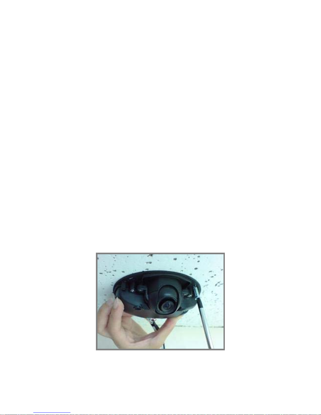
Step 1: Lock the screws by the main to fix the IP camera into the ceiling or
wall.
Page 8
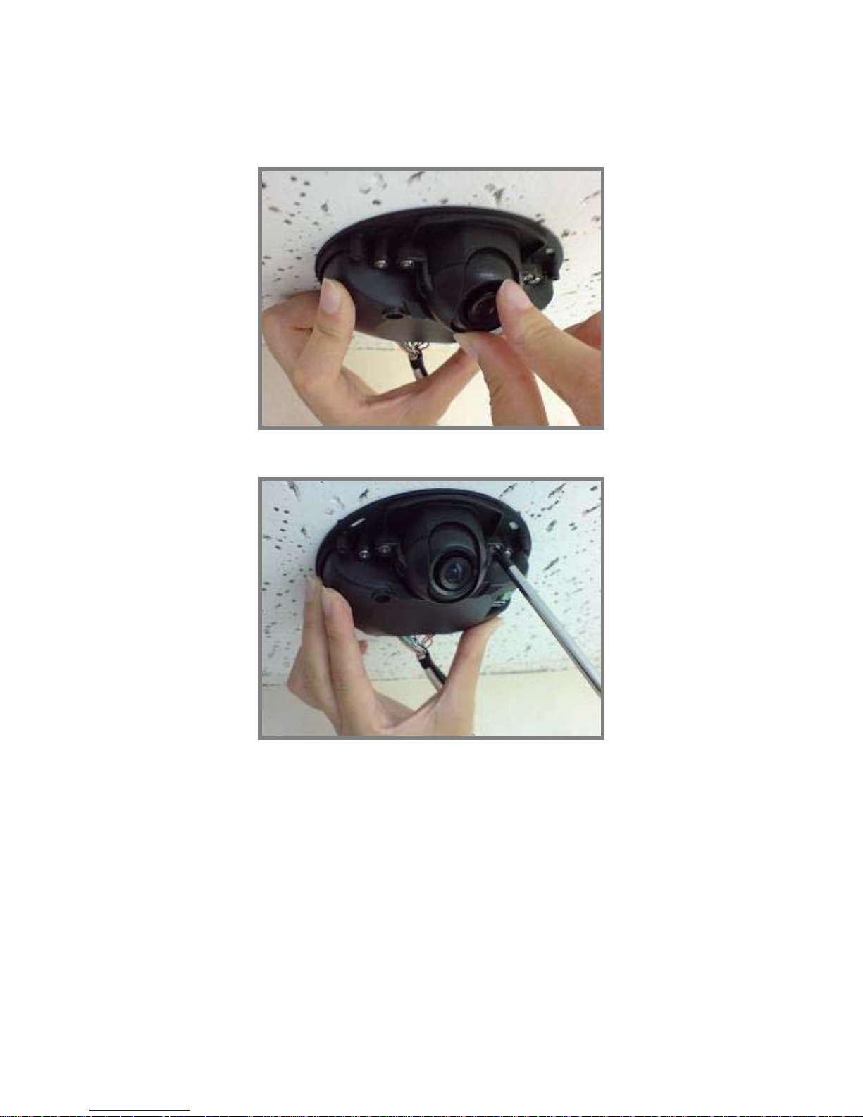
Step 2: Lens can be adjusted to the specific angle as required
Step 3: Lock the screw to fix the front holder (this action is required)
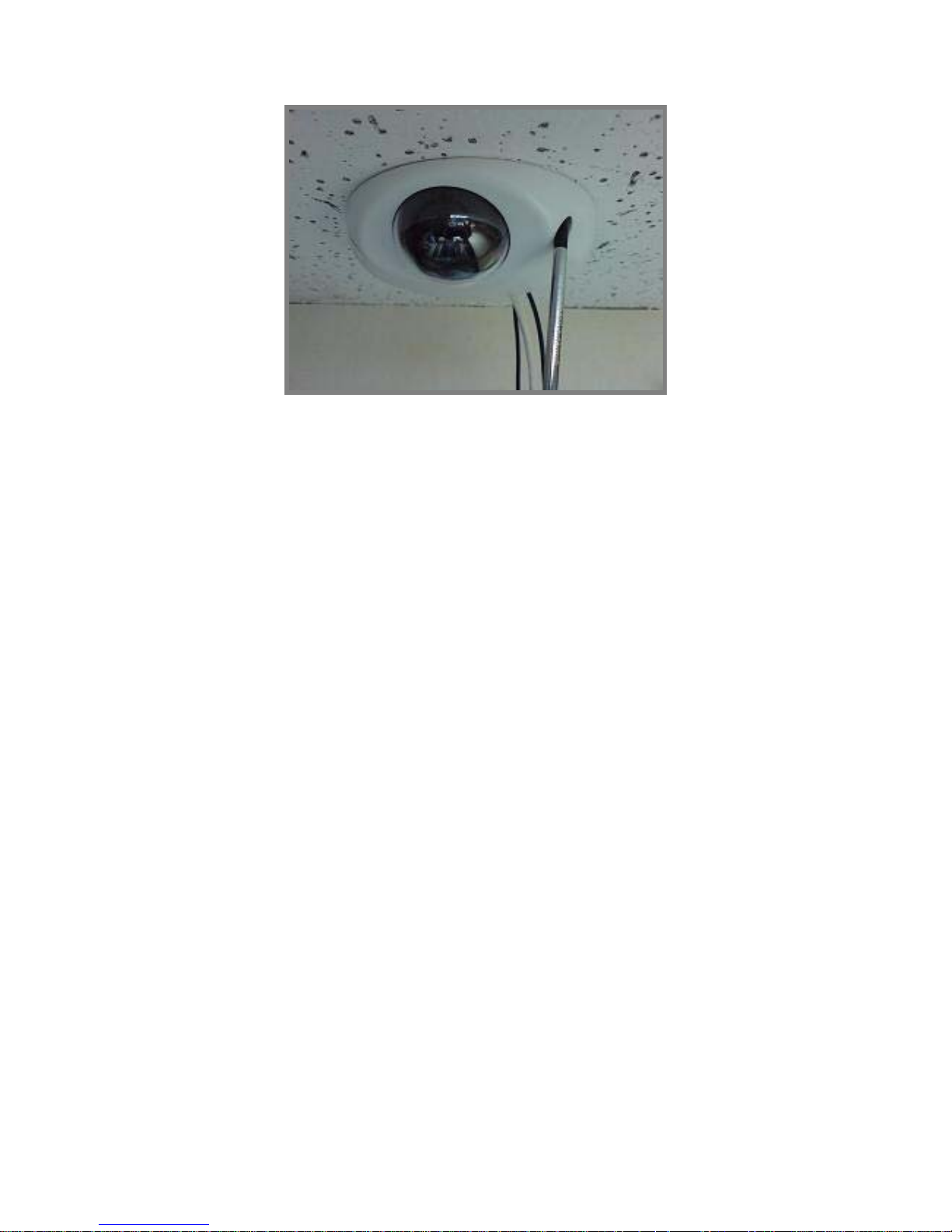
Step 4: Use the white lid to cover the inner part of IP camera
Page 9
Page 10

3. USING EV6552A / EV6552AP
FOR THE FIRST TIME
Before You Install Software
Please check PC OS platform. Microsoft Windows 2000 or
Windows XP is capable of running EtroStation™3.0 software.
PLEASE read EtroStation™3.0 user’s manual before installation.
Language Support
English
Install EtroStation™ 3.0
User can easily find the specific IP camera on the network via this
software.
Browser for Live Viewing and Video Settings
Microsoft IE browser version 6 or higher is recommended. Currently
Mozilla Firefox and others are not compatible.
Factory Setting – Initial IP Address
Default IP Address: 192.168.1.2
Gateway: 192.168.1.1
Subnet Mask: 255.255.255.0
Page 11
Network Domain
Alter the IP address of the PC to the same domain of default value
(192.168.1.2). Users may alter the IP a ddress of the IP camera to the
same of PC via EtroScan™. Please refer to page 45 to check detailed
information.
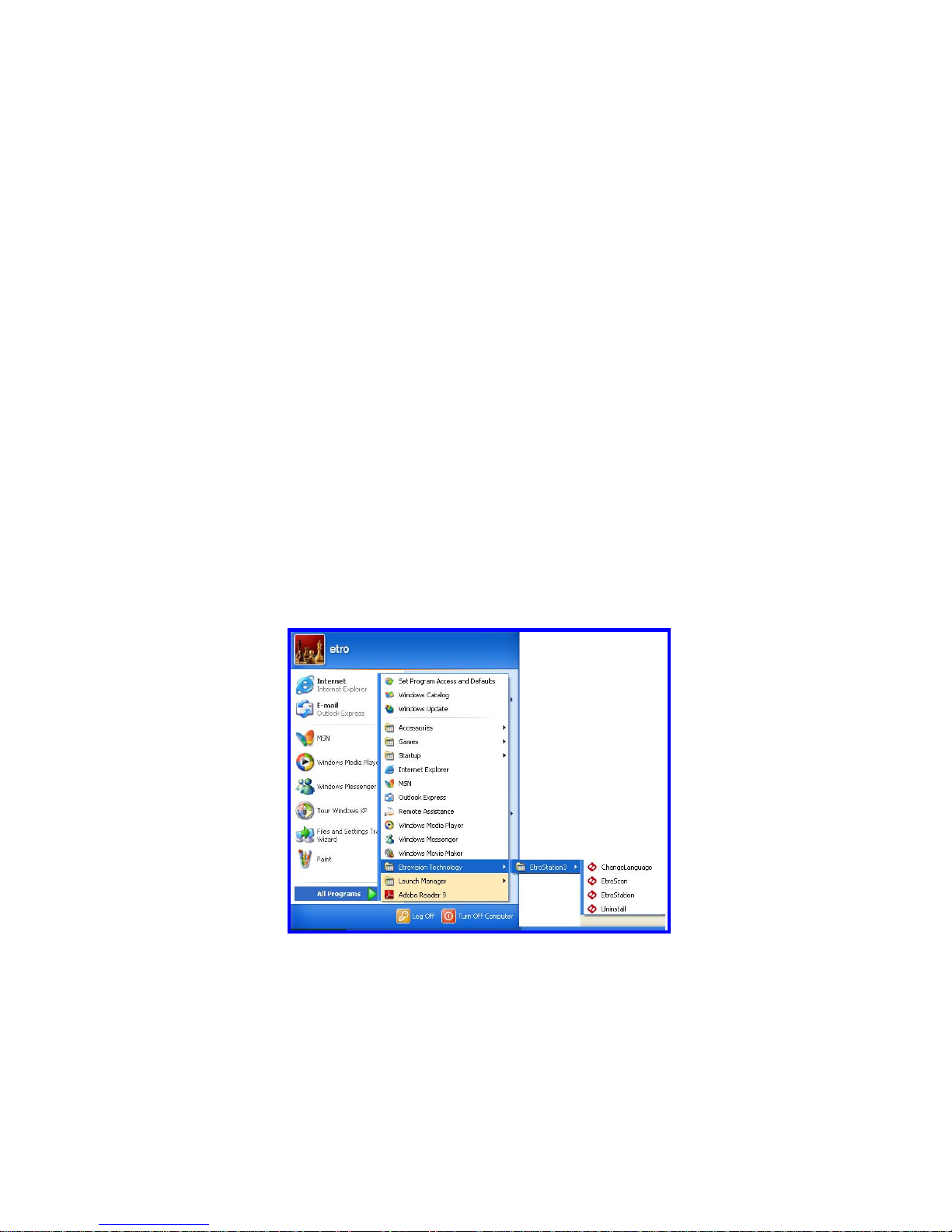
Use EtroScan™
The software allows users easily and quickly find the specific IP camera on
the network. Run EtroStation™ 3.0 setup and install the two applications.
The following is the brief instruction:
Select EtroScan™ from the start menu. User can see the following image:
Page 12
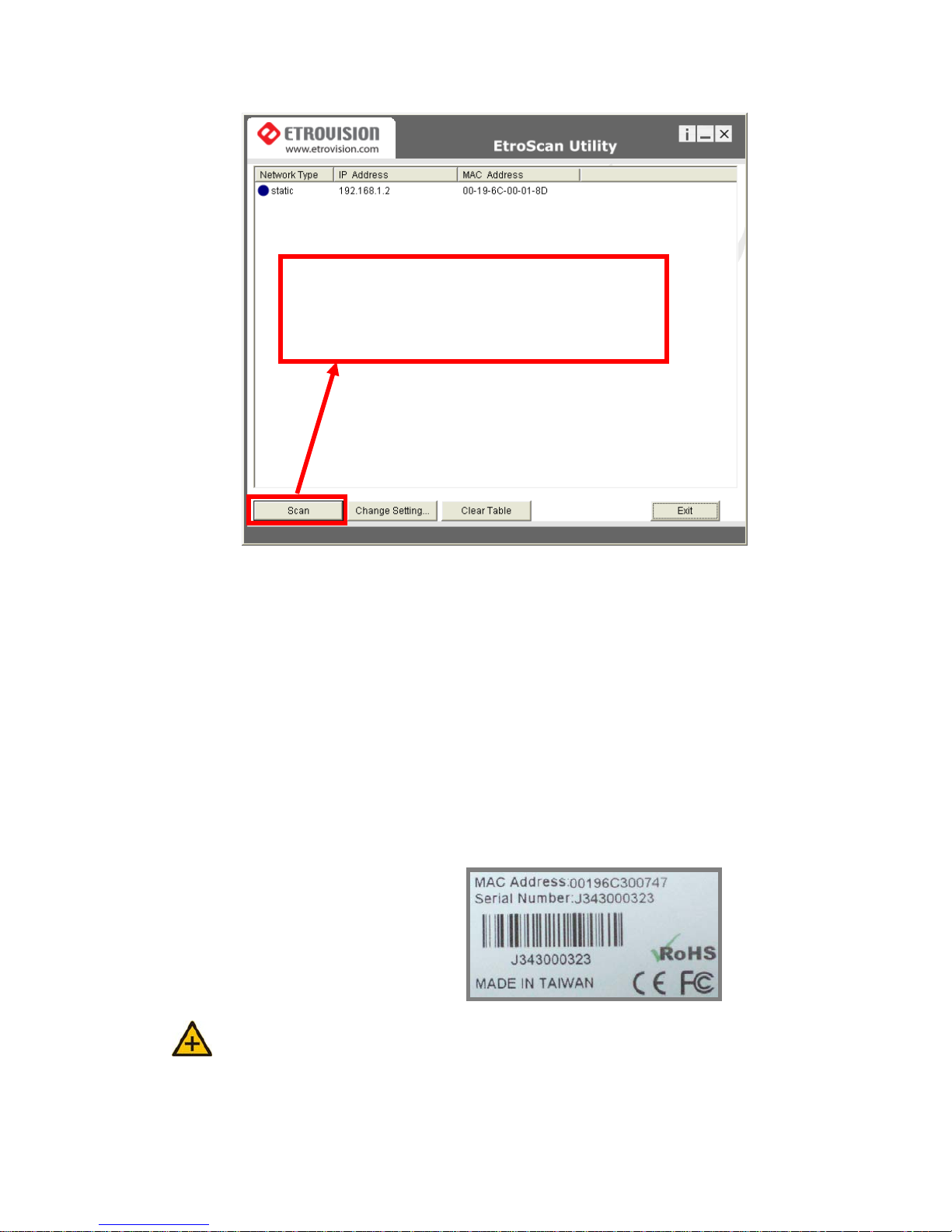
Press Scan button to check the IP and MAC address list. Press Clear
Table button and press Scan again to refresh.
You will find the list of IP and MAC address listed. To indentify your IP
camera you can flip over the IP camera and check the label for MAC
address on the bottom side.
Note: Please pay attention that a completed RMA form must contain the serial
number of the product. For more information, please refer to our website.
Press Scan to automatically find online Video Server or
Full Function of Video Server on the network domain
Page 13
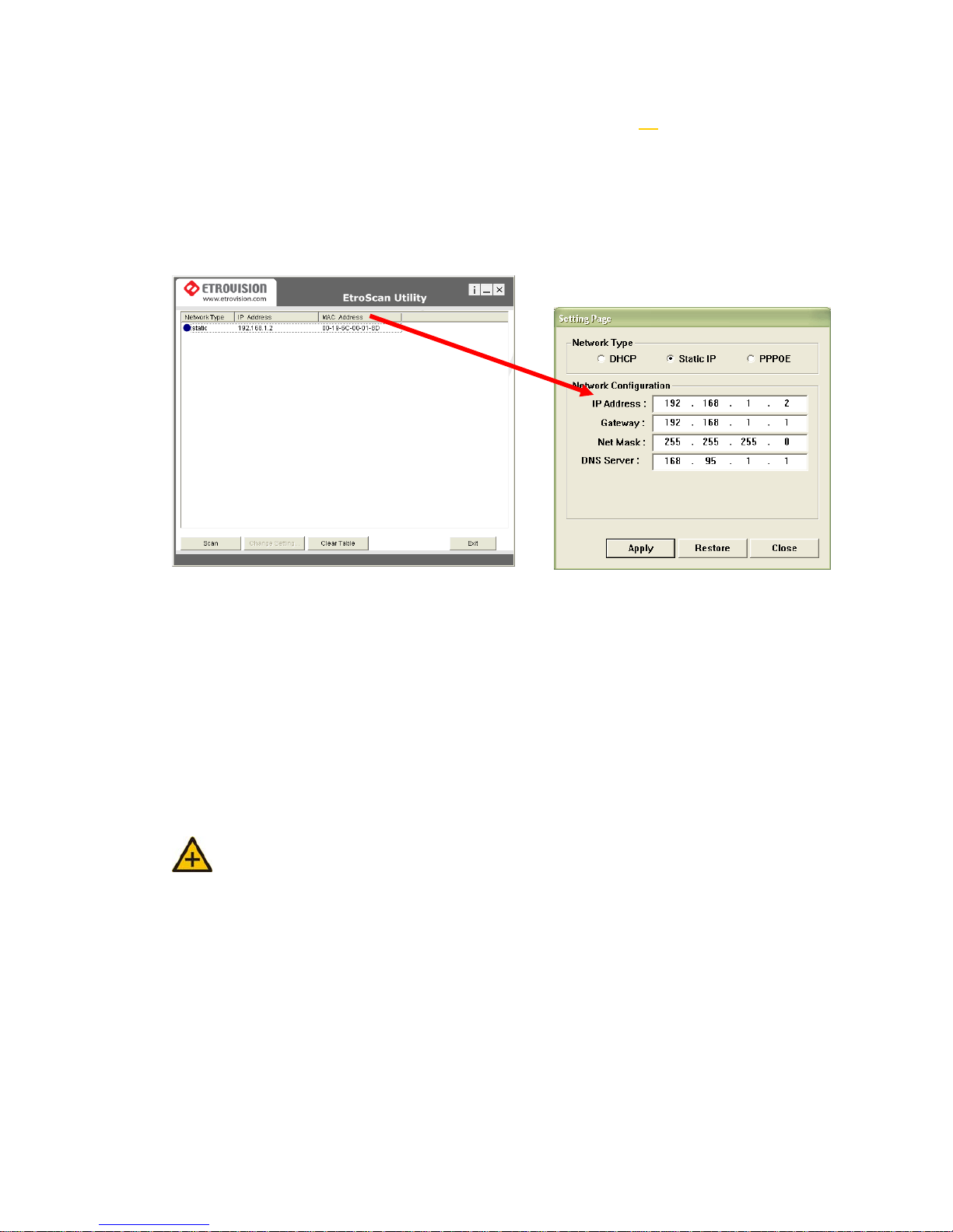
Change Network Setting via EtroScan™
Double click on a specific IP address; the setting page will pop up. Users
may alter some basic network parameters in this page.
Be sure to press APPLY to enable the new setting
Within 10 seconds, the dialog box would disappear . This indicates that the
new settings are deployed. After typing in the new IP address, user may
close the setting page and wait for 45 se conds. It takes 45 seconds to
restart the system. After rebooting, user may press Scan to check the
new IP address.
Note: “DOUBLE Right Click Function” Double right click on a specific IP
address on the list; user can quickly open the live viewing browser page.
Press Exit to quit.
Double click
Page 14
4. ACCESS IP CAMERA
Browser
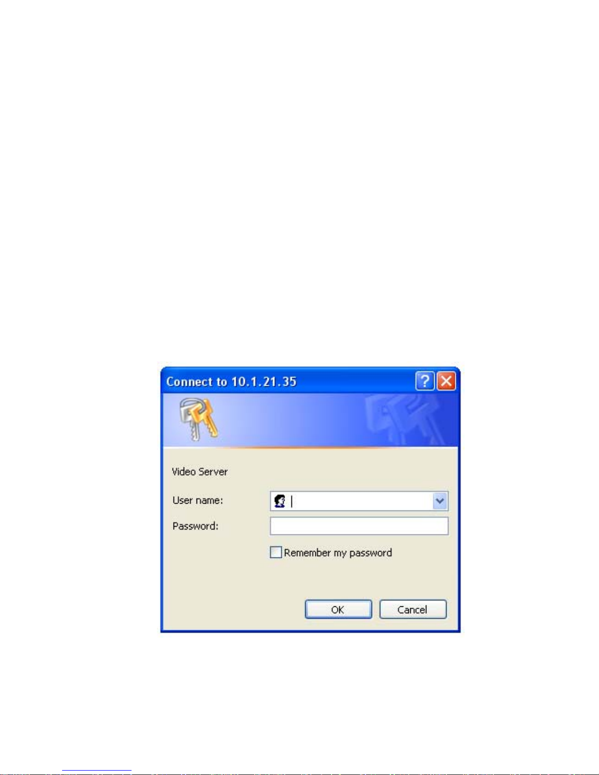
Open an IE browser
T ype in the IP address of video server that you found via EtroSacn™. For
example: 192.168.1.2 (default IP address)
A popup login dialog box will automatically display.
Initial username and password (case-sensitive):
Login: root
Password: pass
Press OK button to access to the live viewing web page.
root
pass
Page 15
Initial Username & Password
Administrator
Default ID / Password = root / pass
The ID of administrator can not be changed or deleted; only the
password is changeable.
Administrator has the authority to view and control system settings.
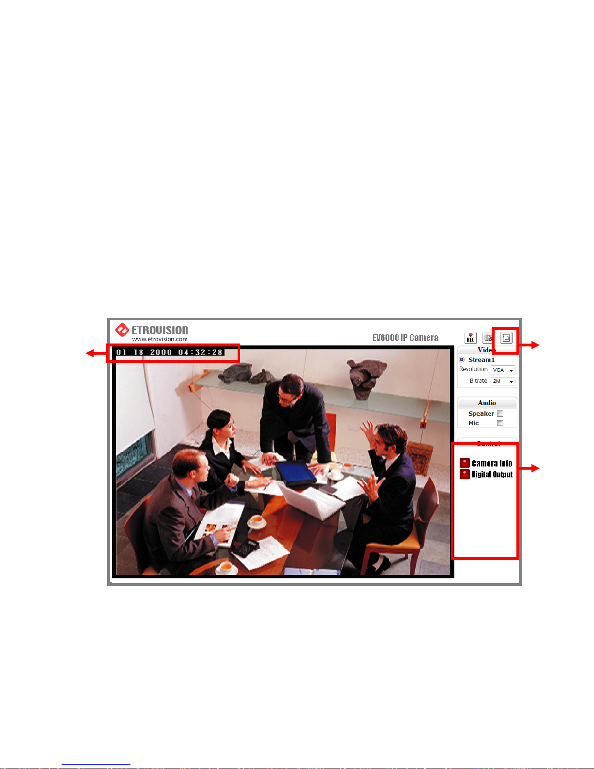
After logging in with root / pass as administrator, user may see the live
viewing page.
1. There is a toggle button on the top right corner of the live viewing
page.
2. User may press this button to switch web configuration page to the
live viewing page and vice versa.
14
3
1
4
4
Page 16
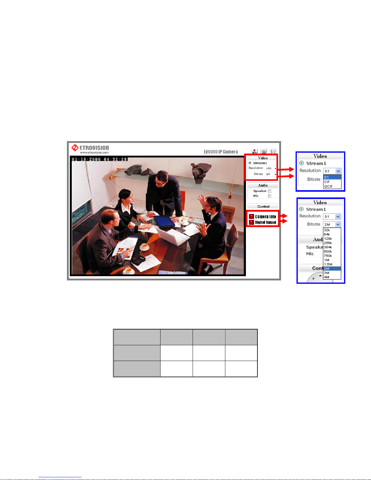
3. Control options are listed on the right side.
4. OSD is displayed on top left corner of the screen.
The sequence is date (mm-dd-yyyy), time, and camera name.
(camera name is optionally displayed)
Control Panel Settings
1. Video / Resolution
The following table shows common resolution format values:
2. Video rates / Bit rates
3. Choose a specific value and the setting will be enabled within few
seconds. The image on the screen might briefly pause.
Resolution CIF QCIF D1
NTSC
352X240 176X120 720X480
PAL
352X288 176X144 720X576
54
4
Page 17
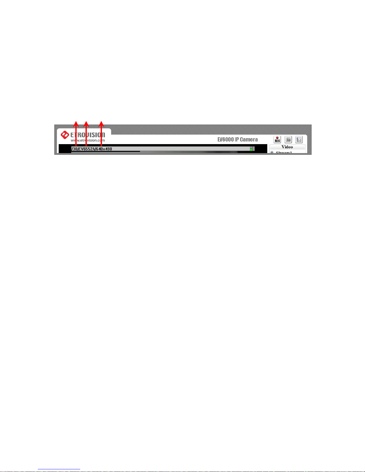
4. Camera information (Please refer to the picture)
The button is on the lower right corner of the living viewing image,
showing video information such as frame rate (fps), model name,
and resolution.
5. Digital Output (Please refer to the picture)
T o enable this function, user has to connect the PIN via the Mini DIN
cable. The toggle button works as a switch to enable/disenable
Digital Out function.
FPS Name Resolution
Page 18
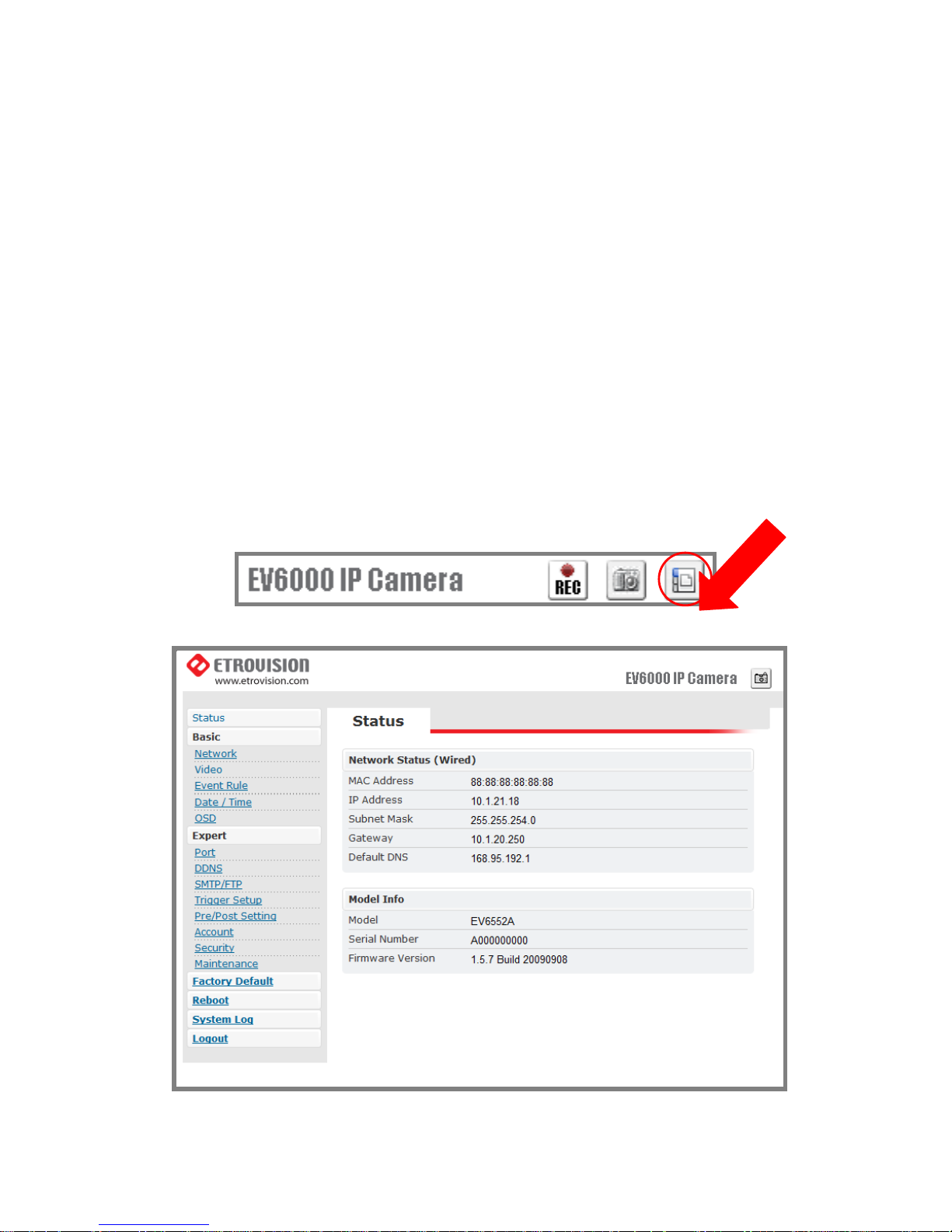
5. WEB INTERFACE SETTINGS –
BASIC
EV6552A / EV6552AP built-in web interface provides the access to
further settings. Enable the top-right side icon in the live viewing page
to access to the further settings. This button also works as a switch
between configuration and live viewing page. (Please refer to the
picture in p.16)
Page 19
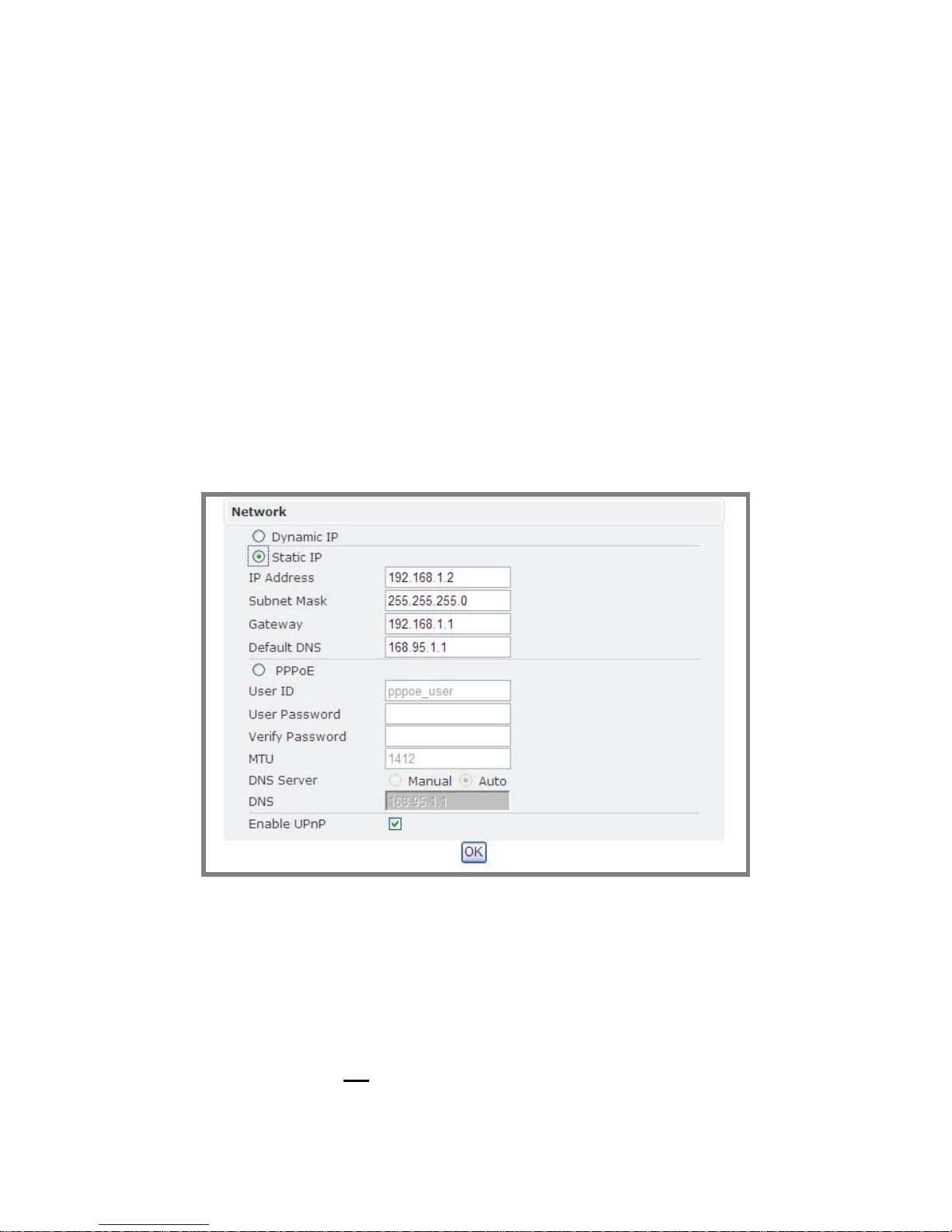
Status
1. Status is the first item of the setting options.
2. This page shows the IP address, MAC address of the video server,
hardware, firmware information, and other related information.
Network
There are three available types of wired network connection: STATIC, DYNAMIC
and, PPPoE.
Static IP
1. IP Address
Please confirm with the network administrator.
2. Subnet Mask / Gateway / Default DNS
Please confirm with the network administrator.
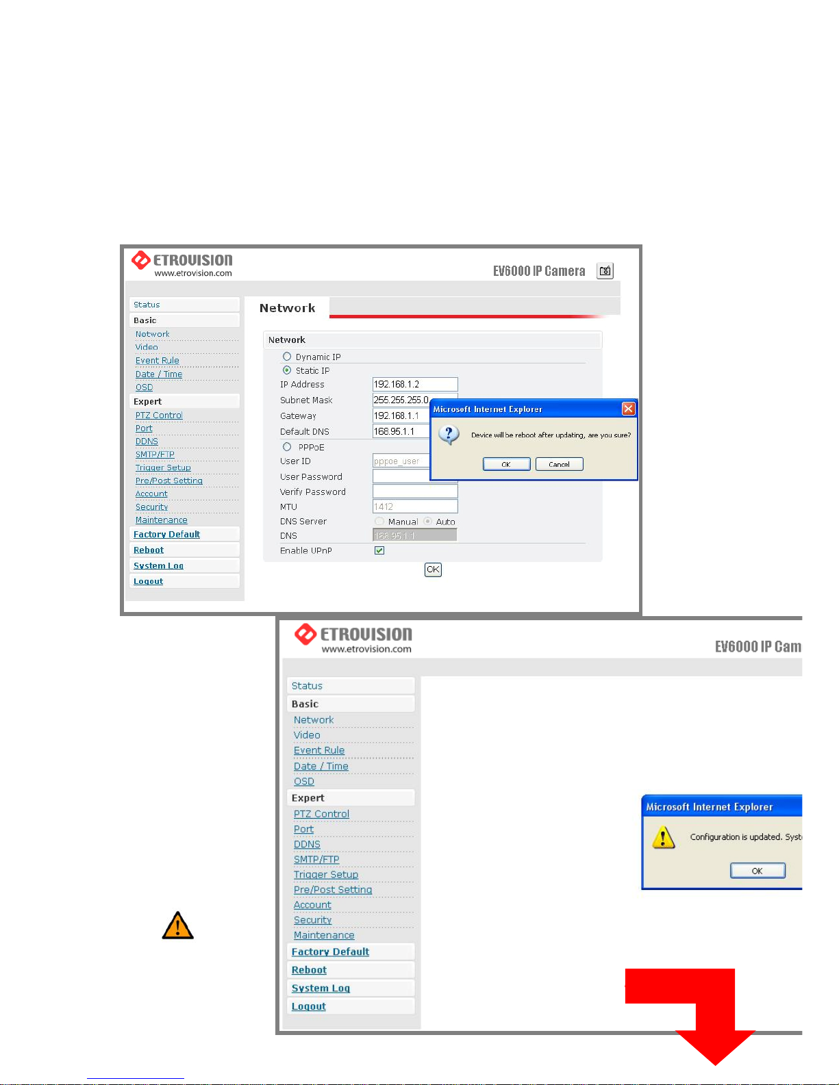
3. Be sure to press “OK
” to save the new setting.
4. Reboot will be required and automatically triggered after pressing OK.
Page 20
Please wait for a moment to the count down timer stop. The page will be
redirected to the initial login one.
Note: Always use EtroScan™ to find the MAC addresses after reboot and
double check the IP address. Make sure the IP address is correct. If IP was changed
in web configuration, you cannot return to initial login page after reboot.
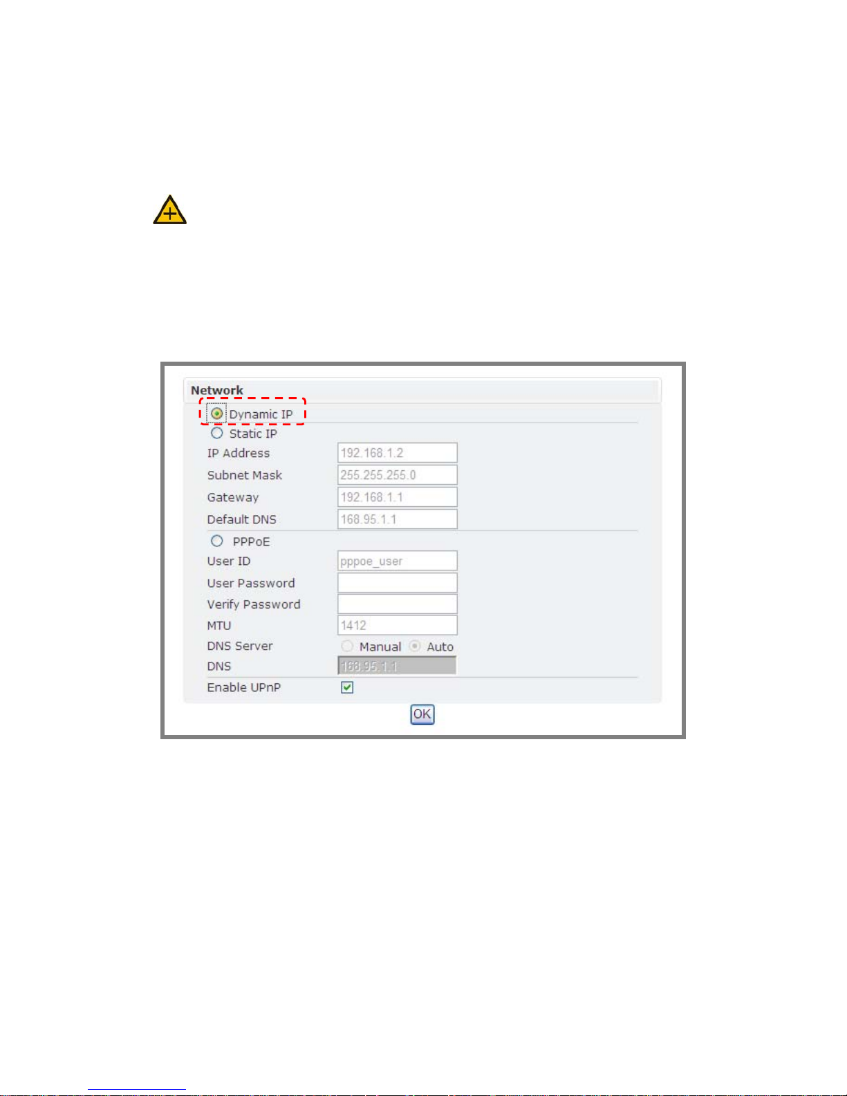
Dynamic IP
1. If DHCP server is on LAN and you want to allocate Dynamic IP address,
use DHCP.
2. Press “OK” button.
3. Reboot will be required and automatically triggered after pressing OK.
4. Please wait for a moment to the count down timer stop. The page will be
redirected to the initial login one.
Page 21
Note: Always use EtroScan™ to find the MAC addresses after reboot and
double check the IP address. Make sure the IP address is correct. If IP was changed
in web configuration, you cannot return to initial login page after reboot.
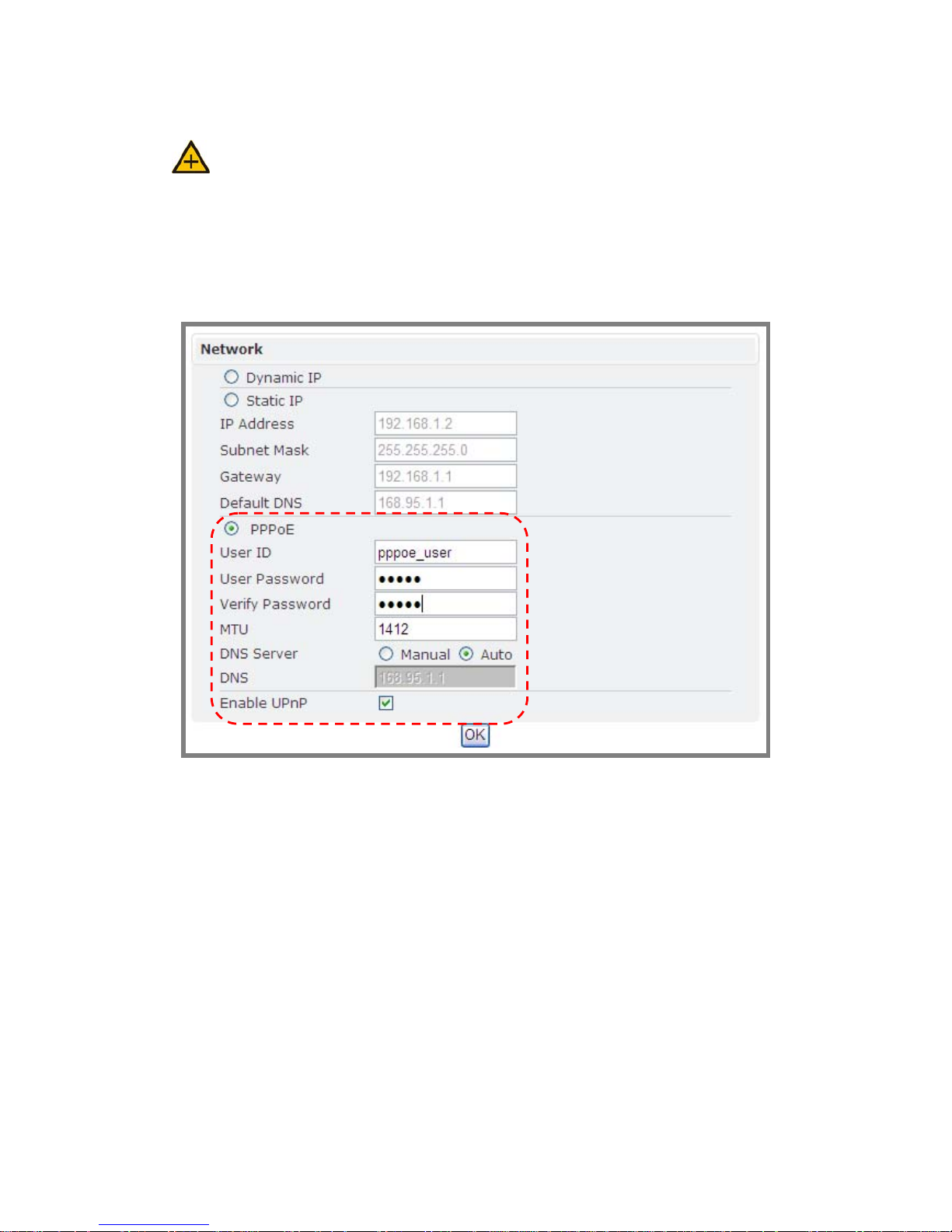
PPPoE Settings
1. If the network supports PPPoE like xDSL, this option is available.
2. Require ISP (Internet Service Provider) to provide ID/Password.
3. User ID / Password
4. PPPoE user ID / Password
5. Service Name: Service name of ISP
6. MTU
。Maximum transmission unit of data
7. IP address of DNS sever can be set to be automatically created.
Page 22
8. If xDSL does not use static IP, you should use DHCP.
Caution: Be sure press “OK” after you have changed the setting in a
particular setting page. After few seconds, a confirmation dialog box will pop up to
Page 23
indicate that the setting has been updated. To return to the same page, please press
“OK”.
Video
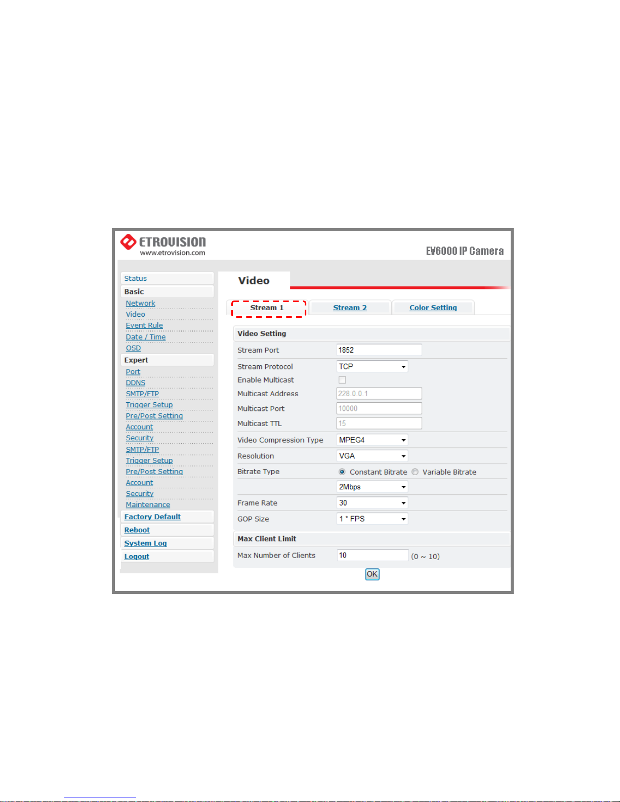
Stream 1
Video Settings
1. Stream Port: Stream 1 port value setting
2. Stream Protocol: Selectable options: TCP/UDP (RTP) / User can decide
whether to enable multicast function or not (If UDP is selected).
Page 24

3. Video Compression Type: Selectable options : H264/M-JEPG / MPEG-4
4. Resolution: Selectable Options: VGA/QVGA /QQVGA
5. Bit rate T ype: There are two selectable options: constant bit rates (CBR)
and variable bit rates (VBR), providing the flexibility in choosing
bandwidth.
6. Constant bit rates (CBR): 4M / 3M / 2M / 1.5M / 1M / 750K / 500K / 384K
/ 256K / 128K / 64K
Note: 1M is recommended when using H.264; 1.5M is recommended when
using MPEG-4.
Note: When mosaic or fragment occurs in the image, users may lower the
frame rate or assign another level of image quality.
7. Variable bit rates (VBR) ranges: 2 ~ 31 (The value “3” is recommended.)
8. Frame per second: 1 / 5 / 10 / 15 / 20 / 25 / 30
9. Group Size (GOP): This function is designed for adjusting the ratio
between “I” frame and “P” frame. Lower the group size represents the
lower bandwidth consumption.
10.Video Type: NTSC / PAL
Note: System can automatically detect the input video signal when the
detect icon clicked.
Max Client
This function allows more than one user to have the access to the video
stream. The relationship between bit rates, resolution, and the client
amount is an inverse ratio.
Page 25
Maximum number of clients depends on the available network bandwidth
and the required video quality. The available range is 0 ~ 10.
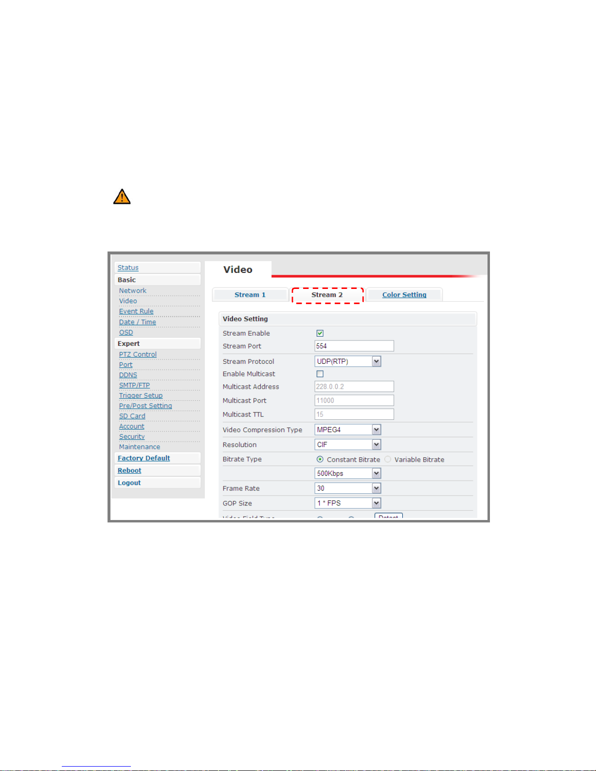
Stream 2
Caution: You have to enable Stream 2 in this section to see the option on the
control panel setting page.
The setting in stream 1 and 2 are the same. ; Administrator can decide
whether to enable this stream or not and see the live video in “Live Viewing”
page.
Page 26
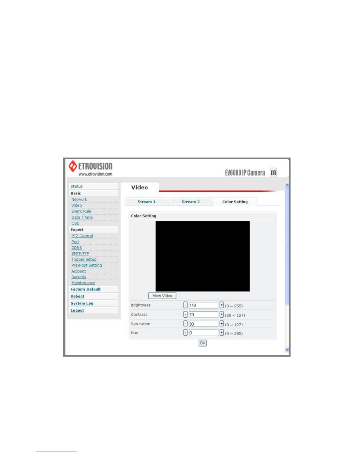
Color Settings
Users may make some fine adjustments to the video quality.
The following is the instruction:
1. BRIGHTNESS: Adjust the brightness of the image.
2. CONTRAST: Adjust the
variation in the intensity of an image.
Page 27
3. SATURATION: Adjust the intensity of color in the image.
4. HUE: Adjust the gradation or variety of a color.
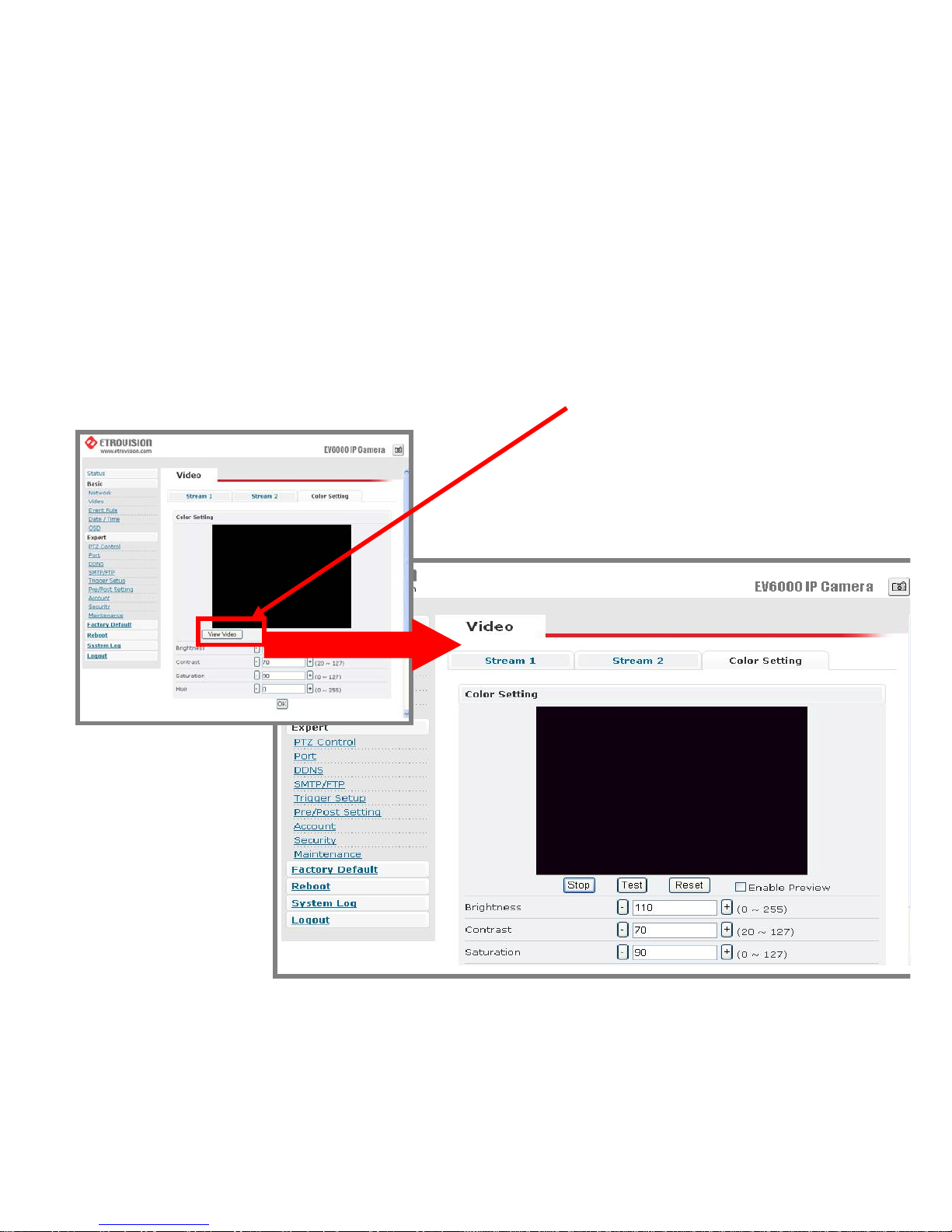
Video Preview
This function makes user easily check the possible change of altering
parameters of setting. By pressing the View Video button, you can se e
the following
Press Stop to exit preview mode. Y ou could alter other parameters and
press TEST to see the expected video image. In the process, u ser can
press Reset anytime to return to the default settings. Press Enable
Page 28
Preview to save the current setting – the new settings will be enabled
immediately.
Caution: Do not forget to press “OK” button to save the current settings.
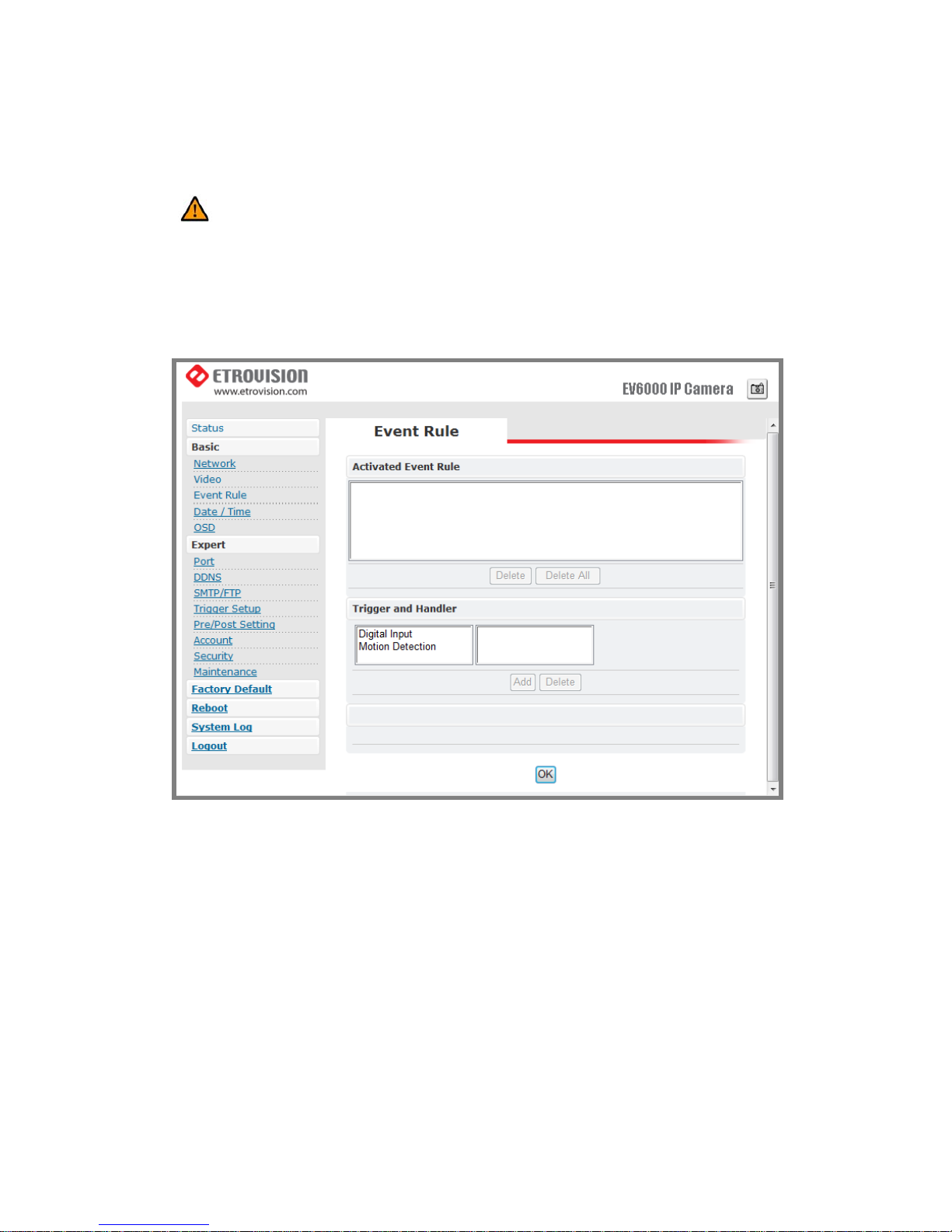
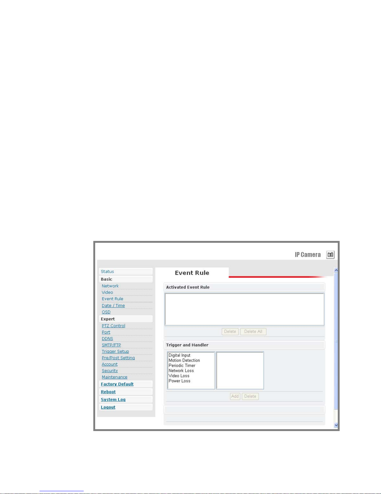
Event Rule
EV6552A/EV6552AP is capable of handling all basic and standard events.
Events handled by EV6552A
1. Digital Input
2. Motion Detection
3. Periodic Timer
4. Network Loss
5. Video Loss
6. Power Loss
Actions supported by EV6552A
Page 29
1. Digital Output
2. E-mail Notification
Events handled by EV6552AP
1. Digital Input
2. Motion Detection
3. Periodic Timer
4. Network Loss
5. Video Loss
6. Power Loss
Actions supported by EV6552AP
1. Digital Output
2. E-mail Notification
Page 30

Events Handled
1. Digital Input: Two options: “Normal Open” (N.O.) or “Normal Close”
(N.C.)
2. Motion Detection: If a motion is detected in the defined areas, an event
will be triggered.
3. Periodic Timer: An event will be triggered following the schedule of the
pre-defined time interval. For example, if the time interval is set
60-second, the event will be triggered once per 60-second.
4. Network Loss: When network loss is detected, an event will be triggered.
5. Video Loss: When video loss is detected, an event will be triggered.
6. Power Loss: When system power loss is detected, and event will be
triggered. The e-mail notification which indicates the time interval of
power loss will be made as powering on.
Actions Triggered
1. Digital Output: Activate digital output.
2. PTZ Preset: PTZ set to a particular preset value can be triggered based on
occurrence of an event listed out in “Rule Lists
”.
3. E-mail Notification: E-mail can be sent based on occurrence of an event
listed out in “Rule Lists
”.
4. Record: When event triggered, system will record streaming to FTP
Server.
Rule Lists – Adding / Deleting
Select an event and choose its corresponding actions. Press add button and
Page 31
notice that is added in the Rule lists Information box.
Modifying Rule Lists
User may press Delete All to delete the items of event rules.
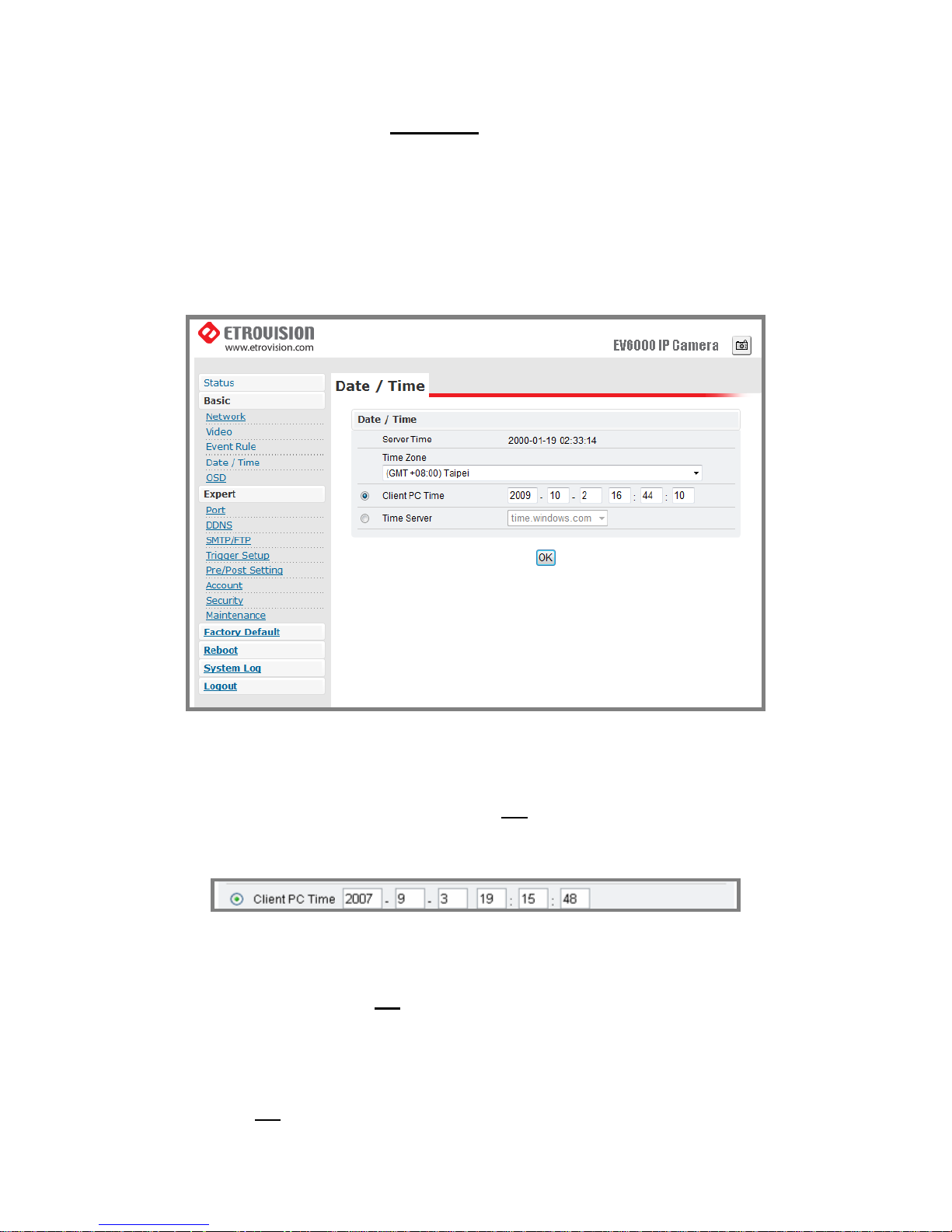
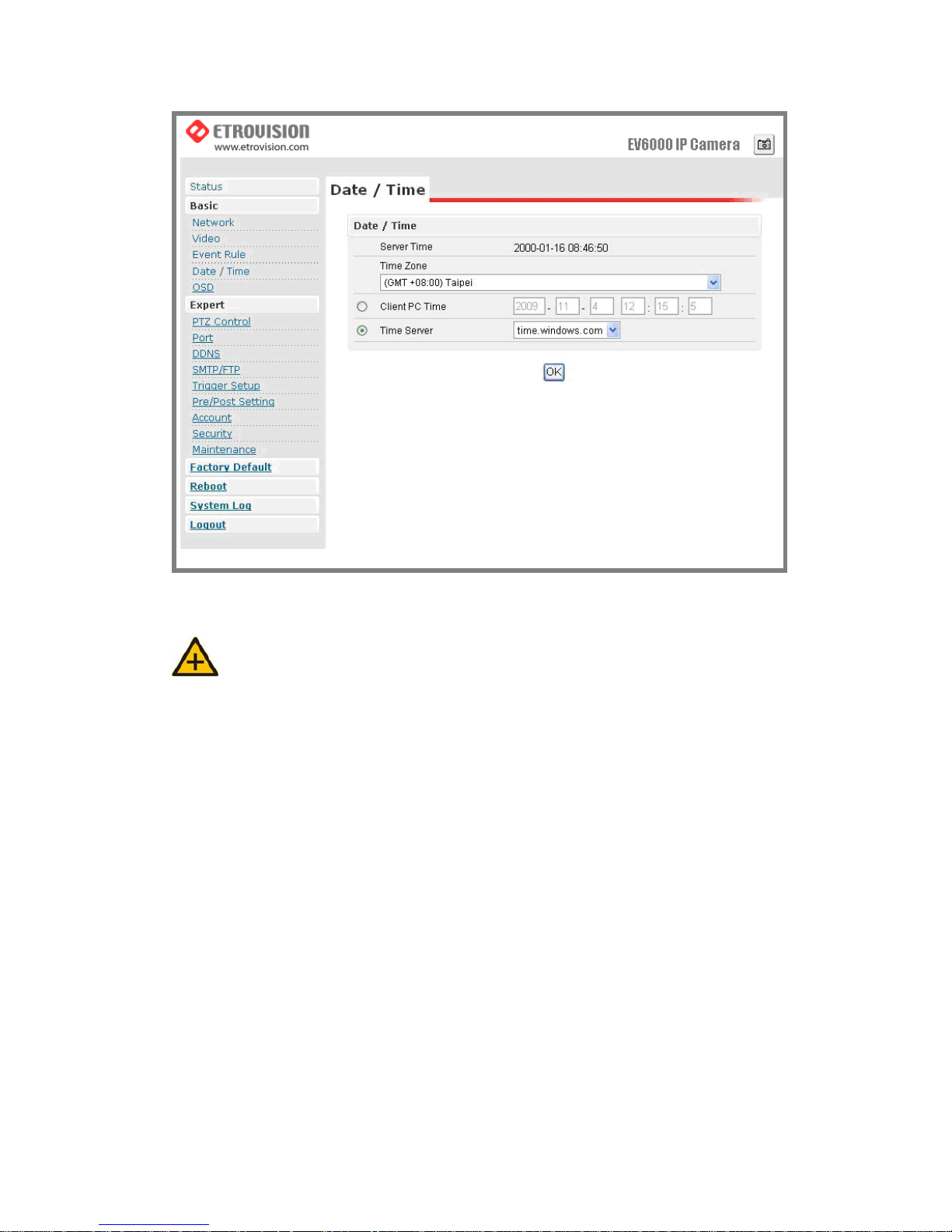
Date & Time
1. Press the “Client PC time” check box, Date and time setting can be
synchronized with PC directly. Press “OK
” after you have the setting
done.
2. Time zone can be chosen from the two listed time servers.
3. After selecting, the time server can be set to synchronize the time of
video server.
Press “OK” after you have changed settings.
4. If you want to manually input time server, choose “Other” then you can
find a manually input edit box. Key in your preferred time server and
press “OK
”.
Page 32
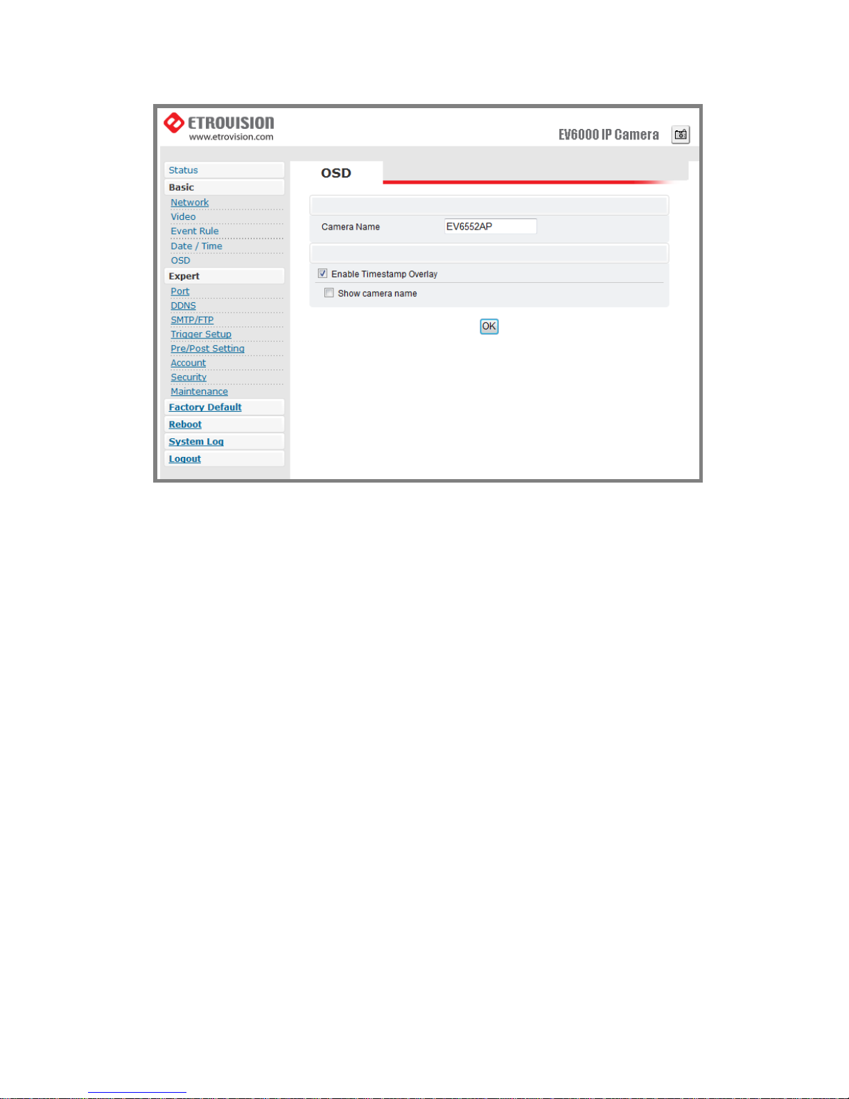
OSD
Note: The OSD and Camera Info. displays are independent.
If “Enable” checkbox is checked, the channel name will be shown on OSD.
If not, this information will be shown on the Camera Info. only.
Page 33
Page 34
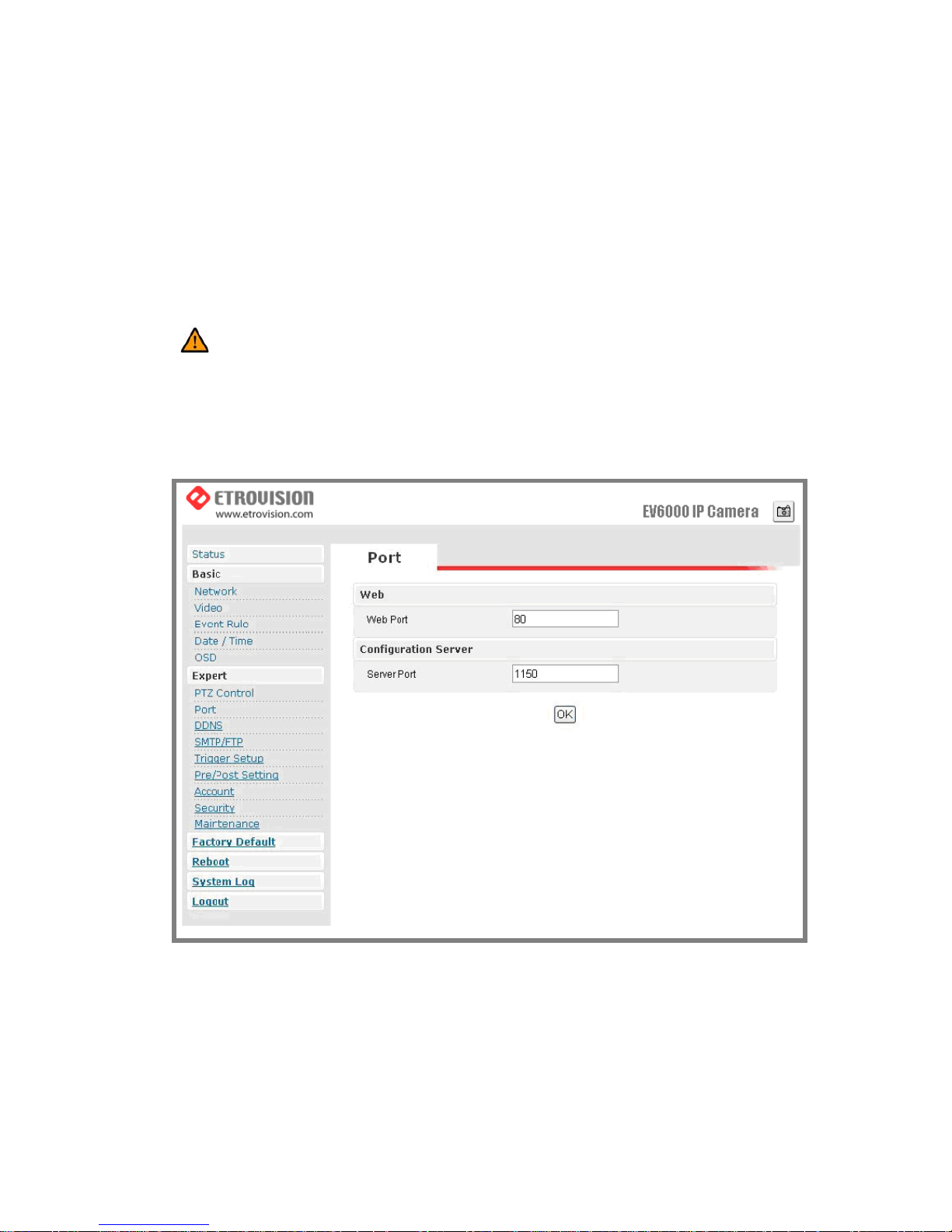
6. WEB INTERFACE SETTINGS EXPERT
Port
Caution: The default port value is 80. Users may change the value. Please pay
attention that if the port is changed (e.g. 80) users have to put: 80 in the end of the
IP address.
The value of WEB and AV port can be changed.
1. Web: The default value of Web Port is 80.
2. Configuration Port: The default port is 1150. (Contacting with your
NVR vendor to check this feature is recommended.)
Page 35
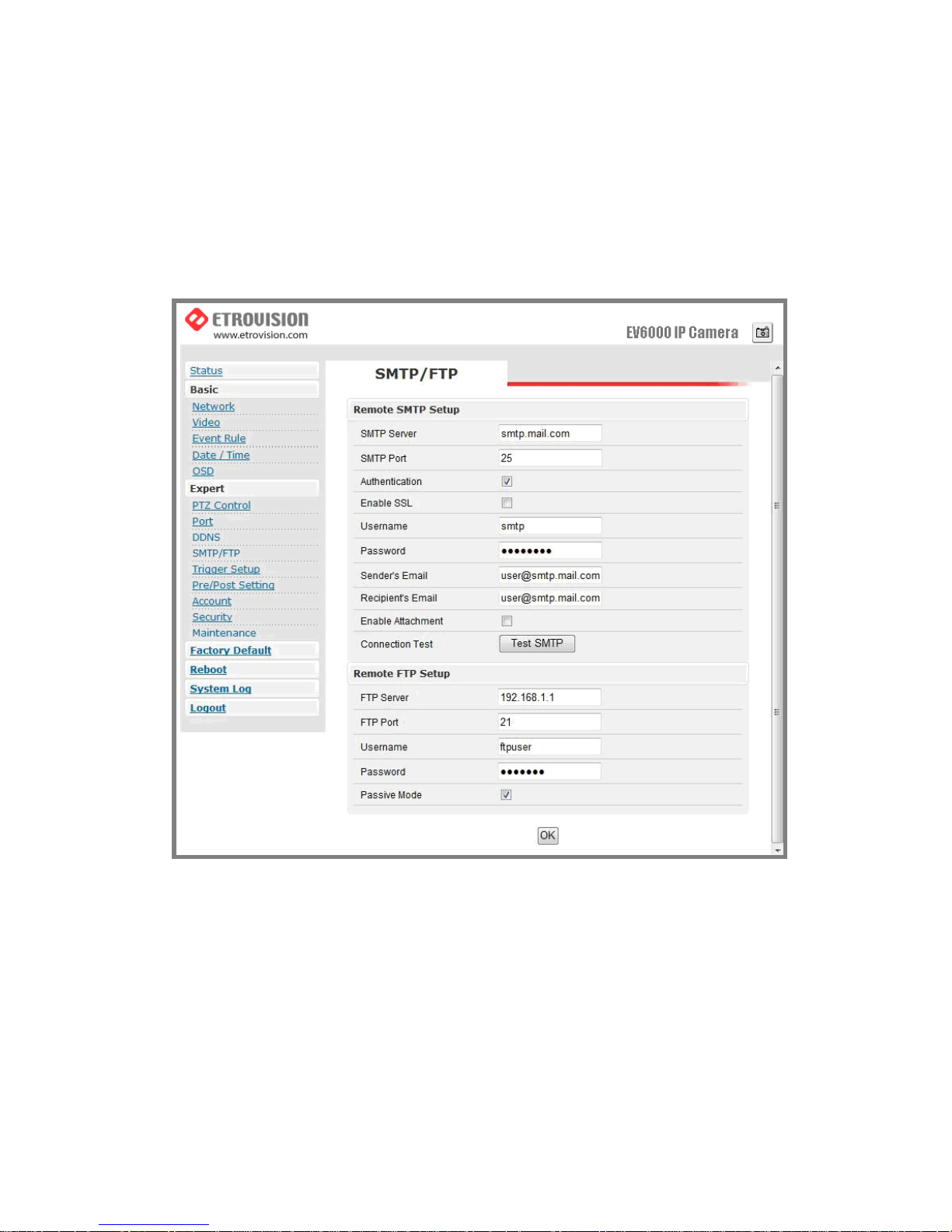
DDNS
The function is used to map an IP address with the host name. If the IP
camera is set a dynamic IP address, the host name must be provided by
DDNS (Dynamic Domain Name Service).
IPv4 DDNS
Check “Enable” and select one from the two options.
Page 36
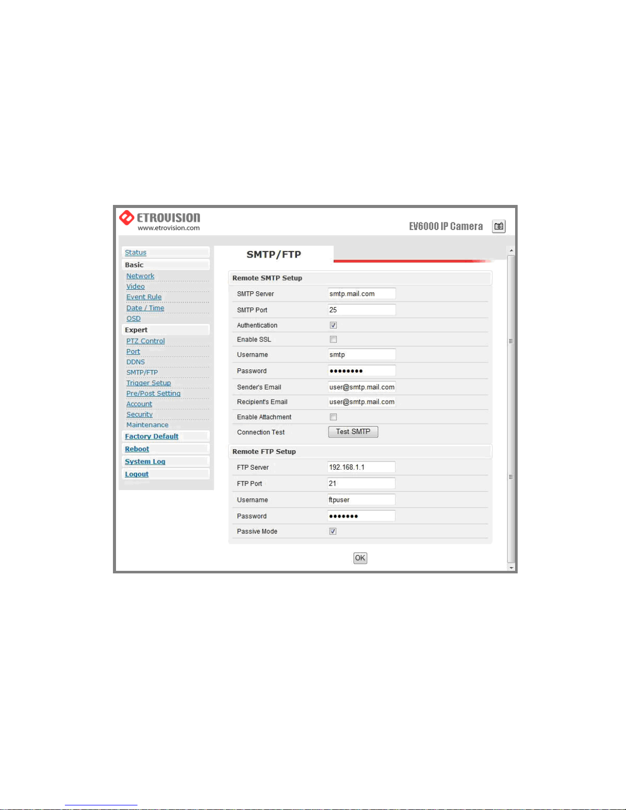
Registrations on DDNS service sites are required for the two
options.
Please go to dyndns.org for registration and further information.
SMTP / FTP
Video Server / Full Function of Video Server support e-mail notification & FTP upload
E-mail – SMTP Setting
Enter the port number, user name, password, and server name informat ion
of the SMTP server. If you’d like to receive the attached snapshots, please
enable the appropriate check box. Authentication is not a mandatory
Page 37
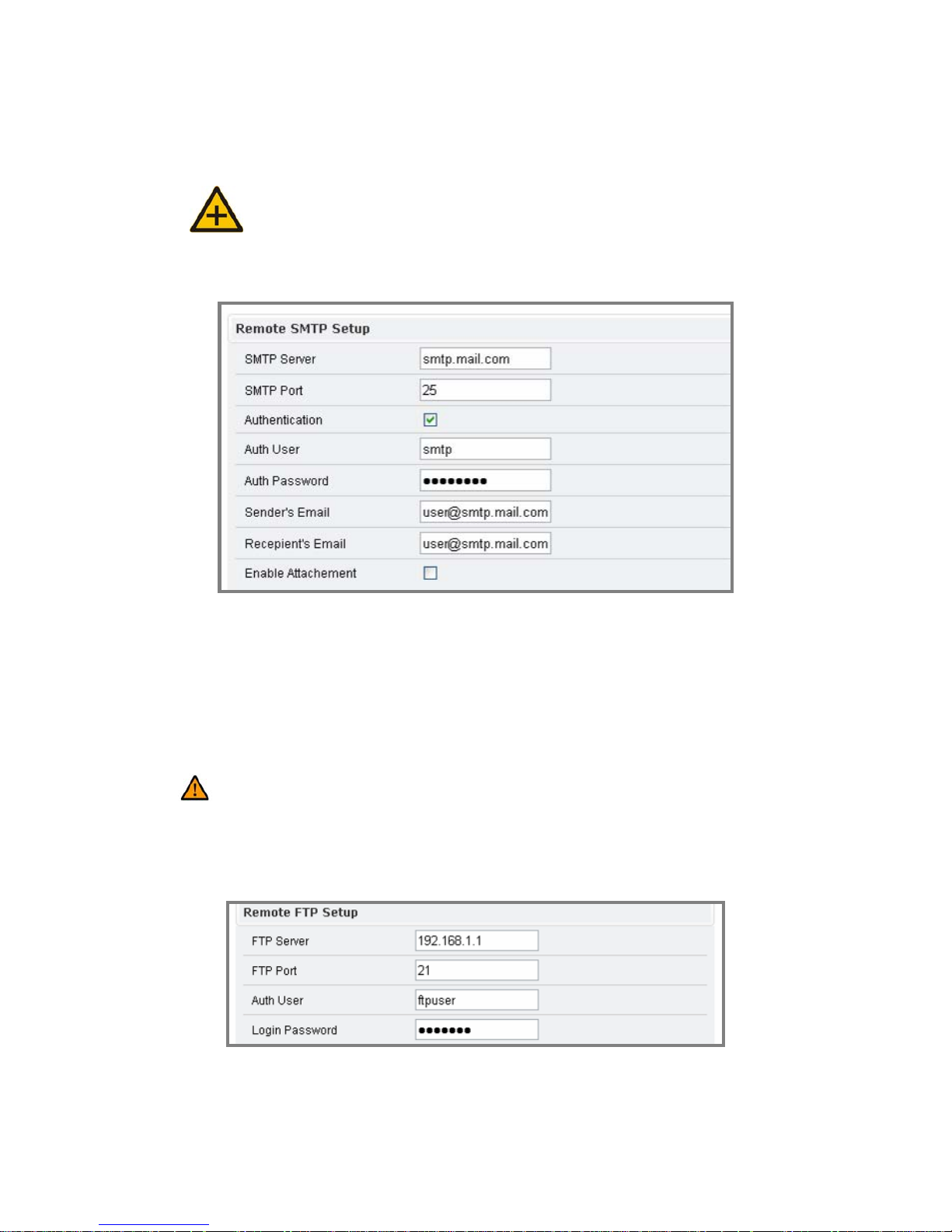
requirement by SMTP servers. In some situations, the required information
includes the SMTP server name and e-mail address only.
Note: Users may define the following parameters.
FTP Setting
Please fill in the address of remote FTP server, port number, user name,
and password.
Caution: Users may assign the port value (e.g.30). Please pay attention that
if the port is changed (e.g.80), users have to put: 80 in the end of the IP address to
facilitate the operation.
Page 38
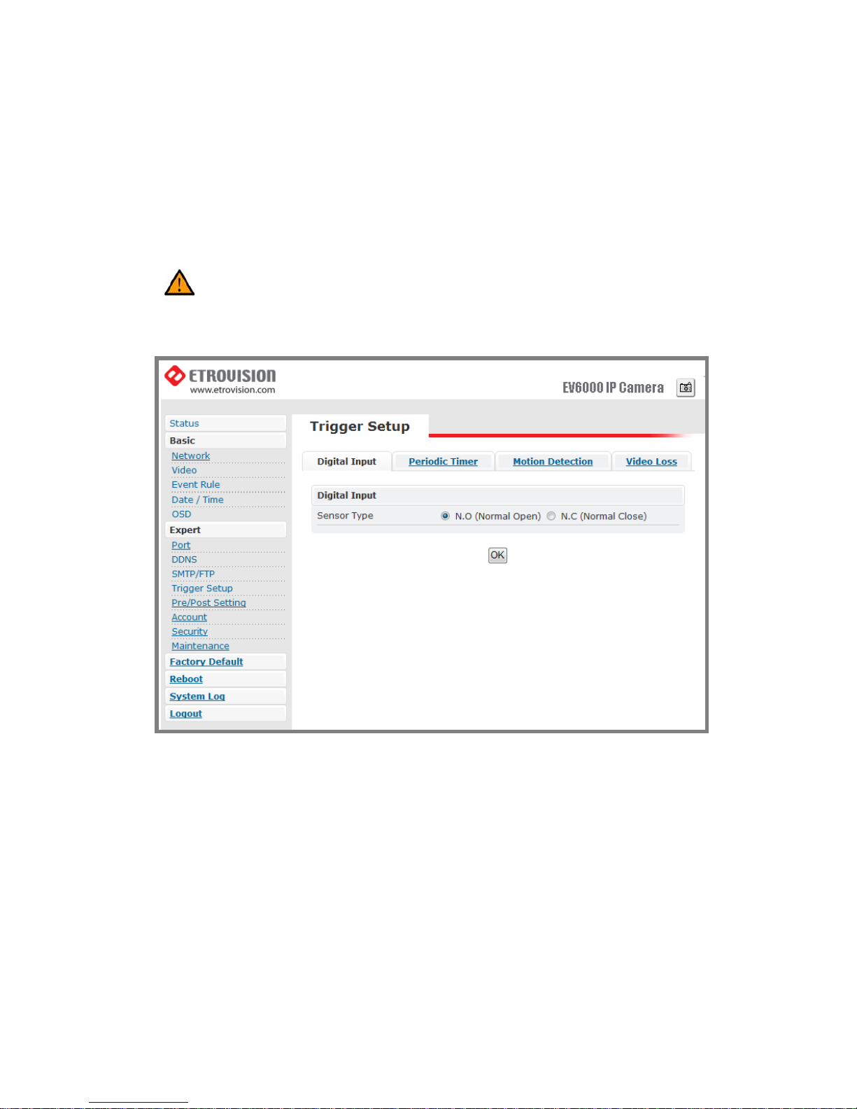
Trigger Setup
Caution: The anode of Mini DIN has to be connected to the anode of the
device to facilitate the operation. So does the cathode.
Three different types of EVENT can be triggered
Digital Input (DI)
There are two selectable options: Normal Open (N.O.) and Normal Close
(N.C.)
Users may choose the proper option depending on the input type. Be sure to
press “OK” to save the setting.
Page 39
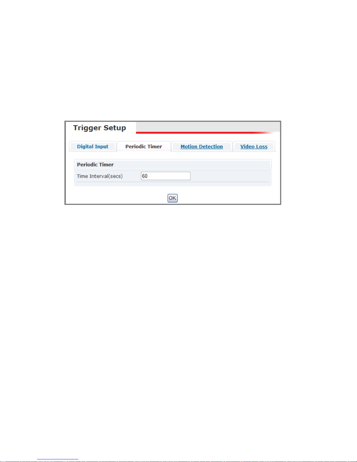
Periodic Timer
Timer interval can be set in terms of seconds. An event will be triggered
according to the schedule.
Motion Detection
Type
a. There are two selectable options: “always” and “schedule” mode.
b. Users can define the schedule as assigning “schedule”.
Page 40

Detection Area: Check the check box to enable Motion Detection;
administrator can self-configure 1~3 detection areas. Click area enable
check box and draw icon, then draw desired area within top preview window;
draw area will be changed into a specific color.
Page 41
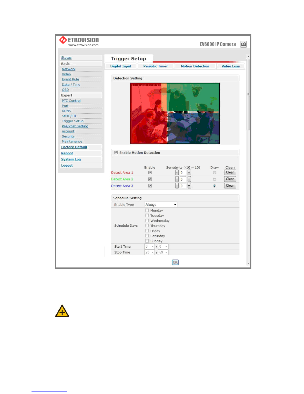
Sensitivity value: Defines the sensitivity of motion detection. The range of
the value is -10 to 10.
*Note: Lower sensitivity value, higher sensitivity level
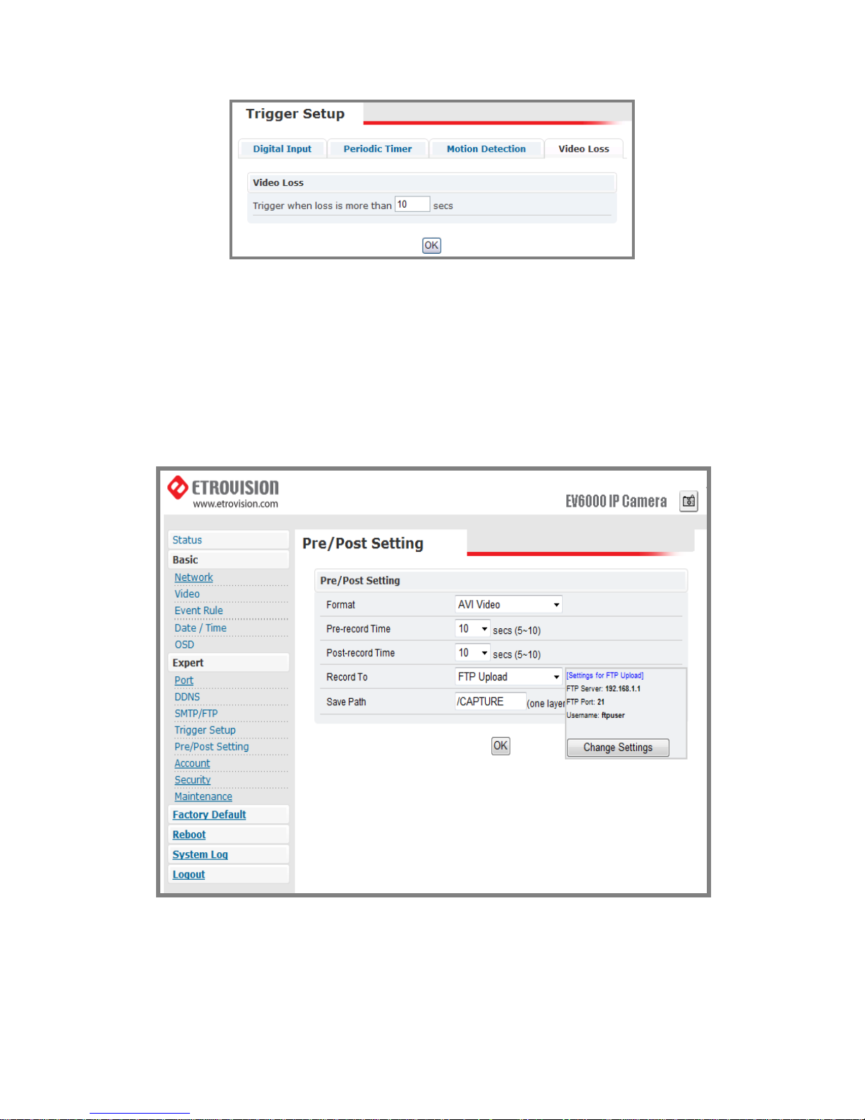
Video Loss
Users may assign the time interval of the event trigger after video loss.
Page 42
Pre/Post Setting
This function is designed for setting the stream format type and time
duration of Pre/Post buffer.
Format options include “A VI” (for video file) and “JPEG ”(for picture file).
Account
Page 43
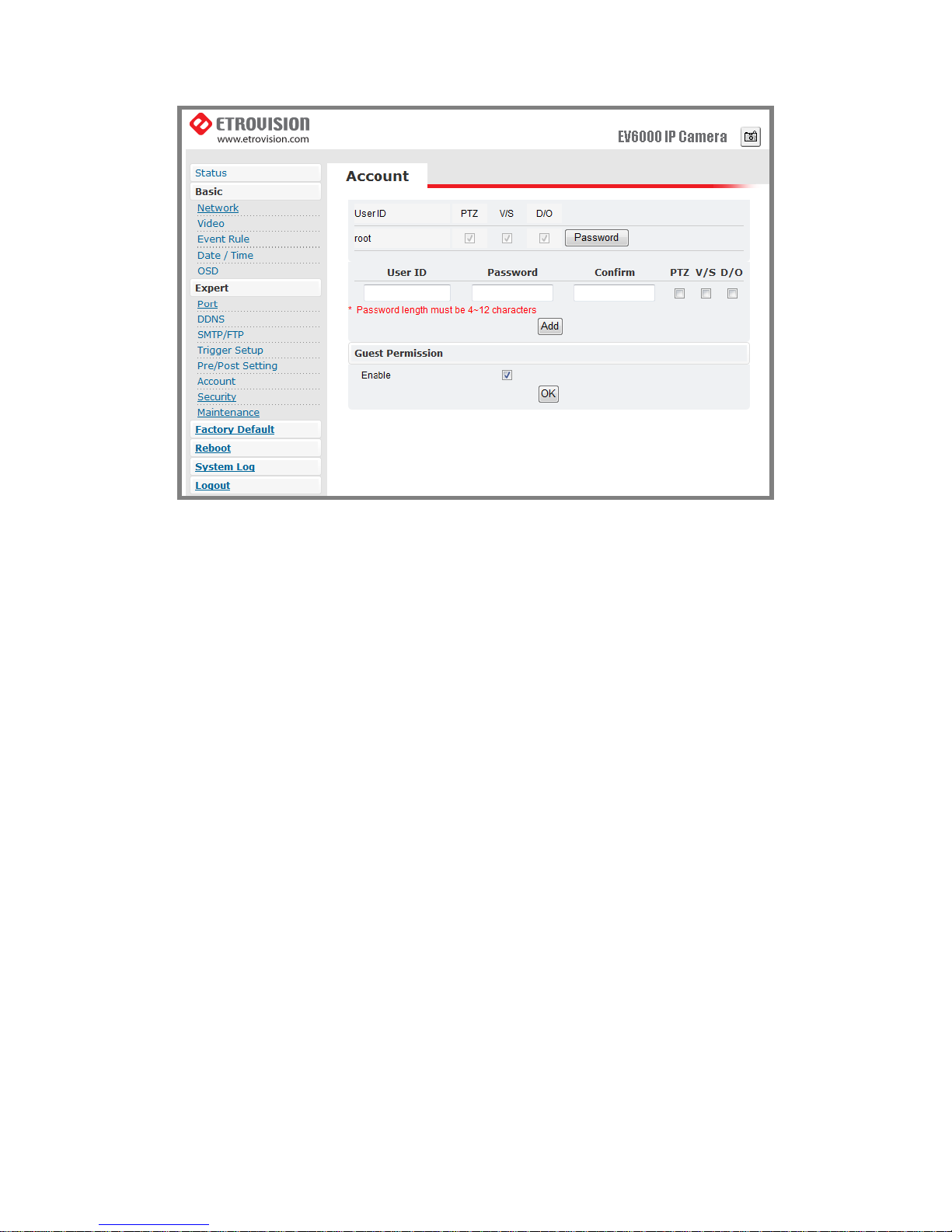
Administrator can create new user accounts. Login as the administrator
and create user accounts by clicking on “Add”. Administrator can assign
different combinations of authorities for each user account. The options
include video settings, and digital out. Administrator may alter the
combination of authorities anytime.
There are limits to the length of user’s name and password. If the length
exceeds the limit, a dialog box will pop out for notification. Guest
permissions can be turned ON/OFF by each individual account.
Page 44
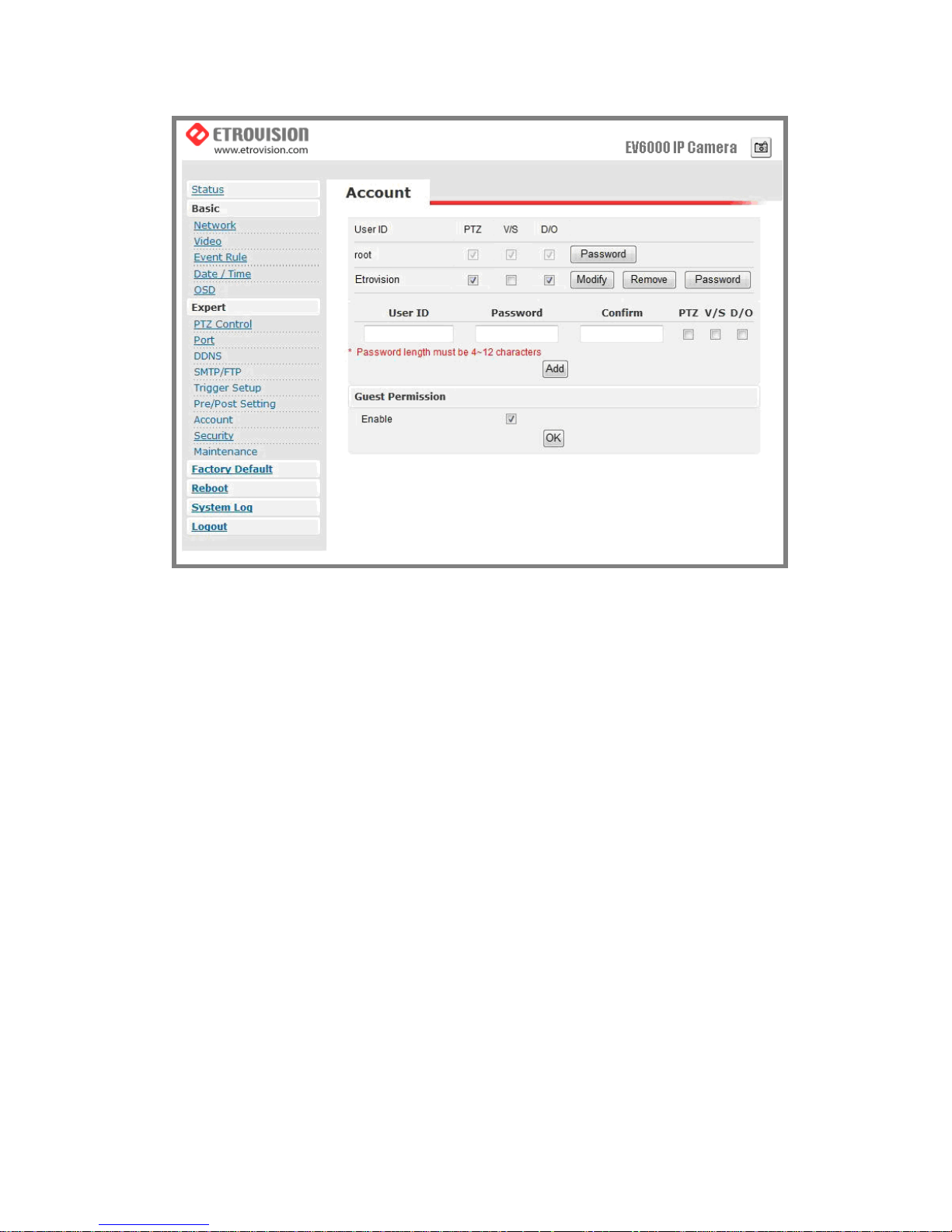
The account name” root” of administrator can not be changed or deleted.
Only the password is changeable. Confirmation will be requested as
changing the password.
Account Limitations
Administrator can add up to 5 users and assign different authorities to each
individual account.
Guest Permissions
Guest account can be turned ON/OFF anytime.
Page 45
Security
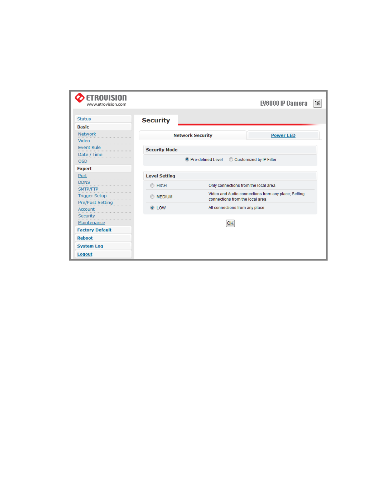
The default setting of security is LOW.
1. Definition of Each Security Level
a. HIGH: ONLY LAN connections are permitted.
b. MEDIUM: Video and audio connections from any location and
settings from LAN are permitted.
c. LOW: All connections from any location are permitted.
2. Power LED
a. Turn On: As the default setting, power LED will always be on during
the operation.
b. Turn Off: Config power LED as off during operation.
Page 46
Maintenance
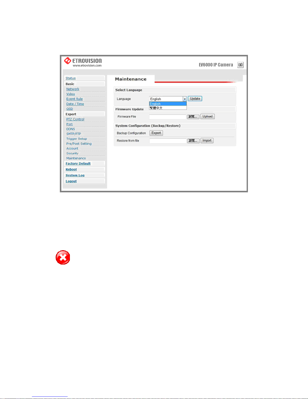
Language
The default setting is English.
Language options include: Traditional Chinese and English.
Firmware Update
Warning: The power supply must be steady as upgrading the firmware. The
power failure during the upgrade process results in serious damage
to the machine.
Users can download the firmware file from Etrovision official website.
Choose the specific one and press upload. When uploading is finished,
reboot will be requested and automatically triggered.
System Configuration (Backup / Restore)
Yo u can backup the current configuration setting and save it as a file.
Page 47
7. FACTORY DEFAULT
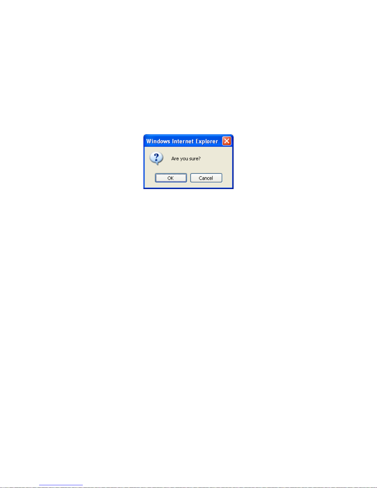
While the confirmation dialog box appearing, press OK button to load
default setting and do reboot. You will see the countdown timer running. The
login page will appear as finishing. Please login with root/pass.
Page 48
8. REBOOT
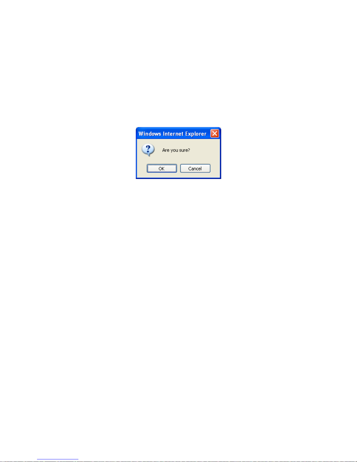
Press Reboot and one dialog box will pop up. Press OK on the dialog box;
the reboot countdown timer will start running. After finishing, the login page
will appear. Please login with the correct account name and password.
Page 49

9. LOGOUT
Press logout to return to the login page. The login page should appear within few
seconds.
Page 50
10. ETROLINK™ CONFIG PORT –
FIRST TIME EXPERIENCE
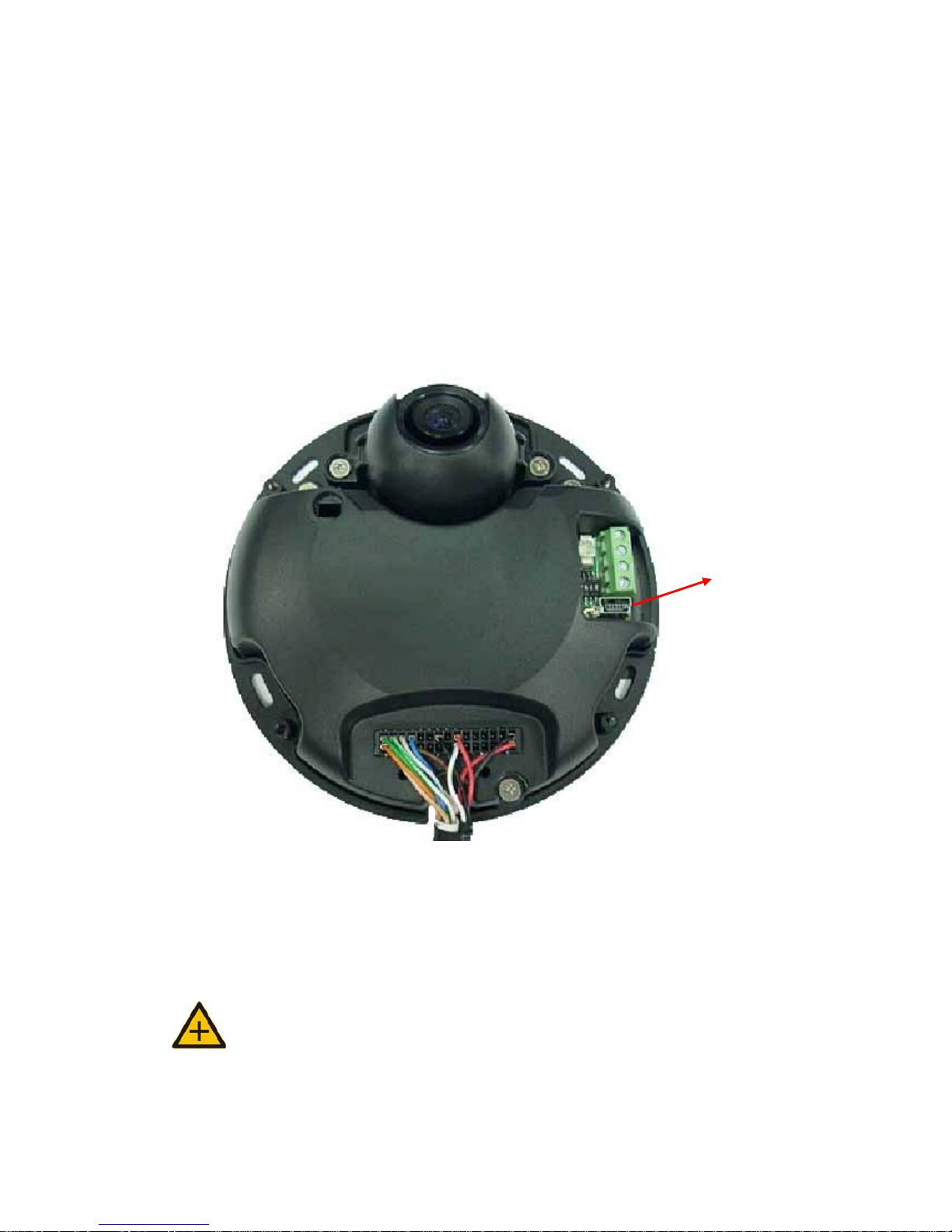
EtroLink™ is designed for quick configuration or factory default. There is
EtroLink config port, a special USB port, on each product of Etrovision.
Connect the IP camera and PC via mini USB cable through EtroLink config
port. Please pay attention that if the IP camera is powered on, EtroLink
will not be operant. After finishing the configuration or factory default,
please unplug the USB cable.
NOTE: Remove USB CABLE when the quick configuration is completed.
Unplug USB cable
Page 51
OS Requirement
Capability of auto/manually run of Quick Config application depends on the
OS of PC.
1. Windows XP (all editions) - auto run.
2. Windows 2000 (all editions) – manually run is required.
3. Windows 98 (SE) – manually run is required.
Note: (Generic USB mass storage class driver (Microsoft) will be
requested –if you plan to use EtroLink™ based device recovery on Windows 98,
please prepare one in advance)
NO Software installation Required
There is no requirement of installation or setup of any software on Windows
XP/2000 platforms.
Steps for Using EtroLink™ Config Port (Windows XP OS)
1. Unplug the power cable from the IP camera.
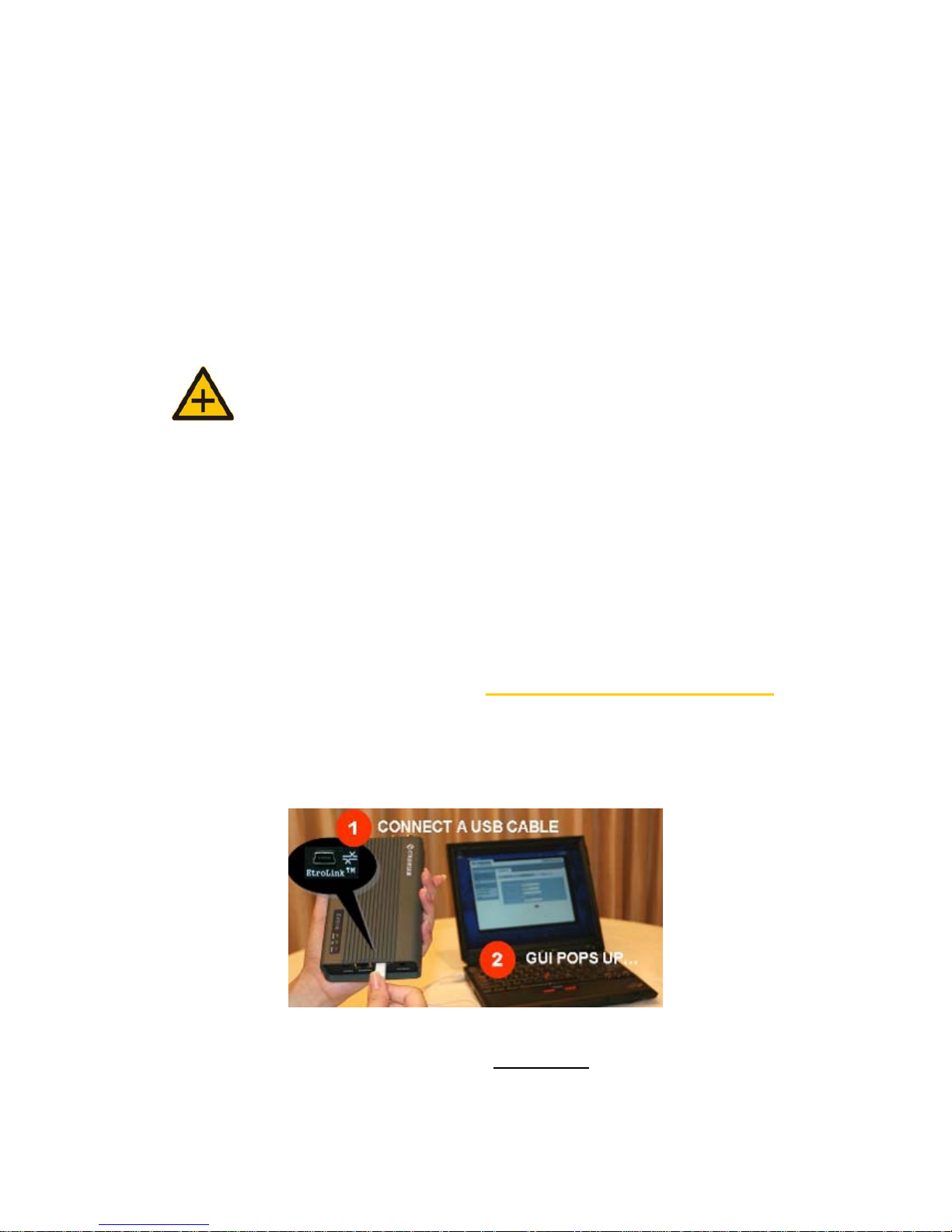
2. Connect EtroLink™ and PC via the mini USB cable.
3. After 5 ~ 10 seconds, the “Disk drive” will be detected. The
detecting speed is determined by the processing speed of your PC.
Page 52
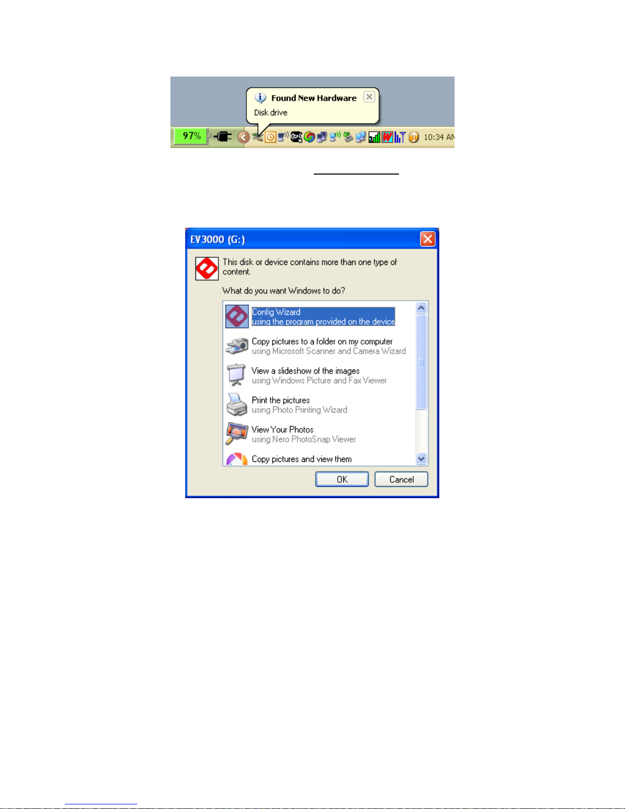
4. A POP-UP dialog indicates “Config Wizard” being ready to run.
Please press OK.
5. Double click on the Config Wizard. You will see the following page:
Page 53
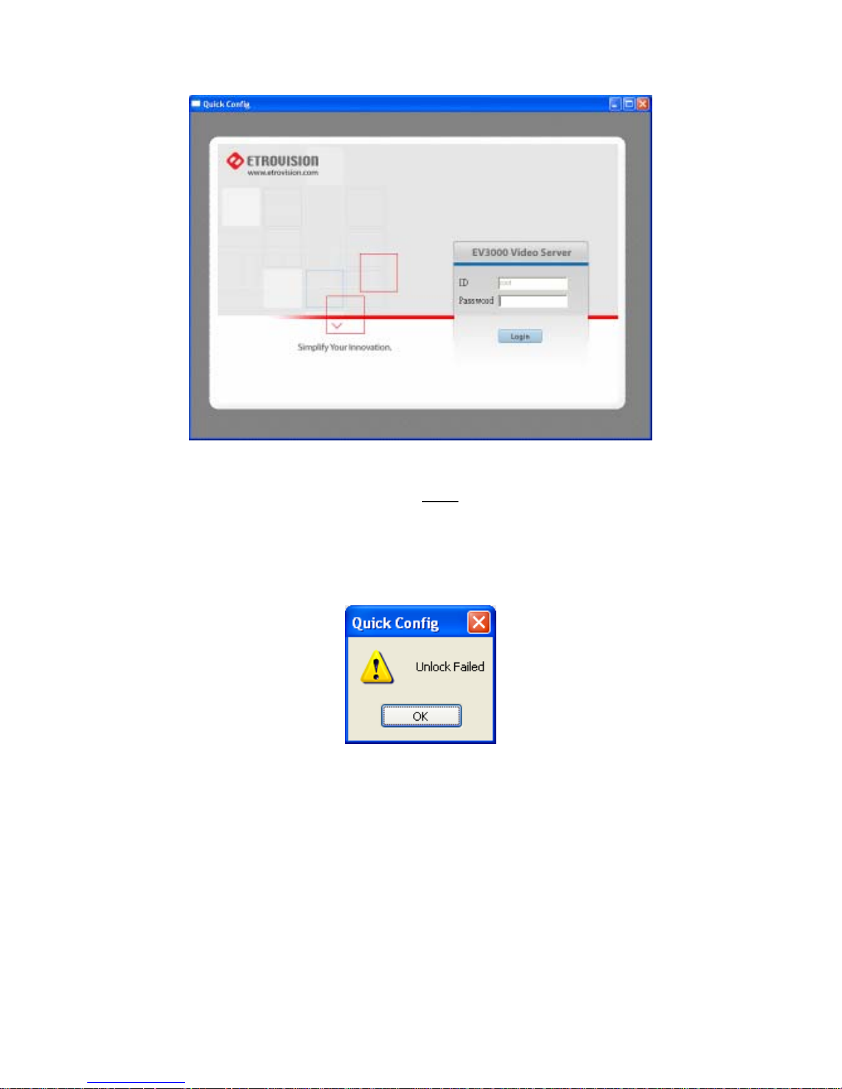
The password is required. If you didn’t change the default
password, please type in pass
. Then press the login button. The
following dialog box will pop up if you don’ t type in the proper
password.
Page 54
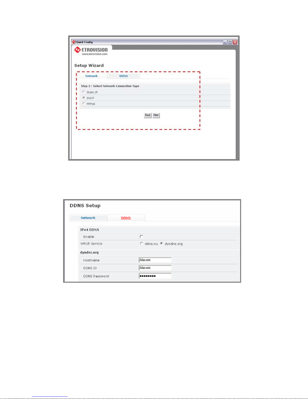
If you’d like to setup DDNS, please fill in the required
information.
Return to Network page to set other network setting. Please press next to
go to detailed configuration setting page. The following page is an example
of STATIC network configuration page.
Page 55
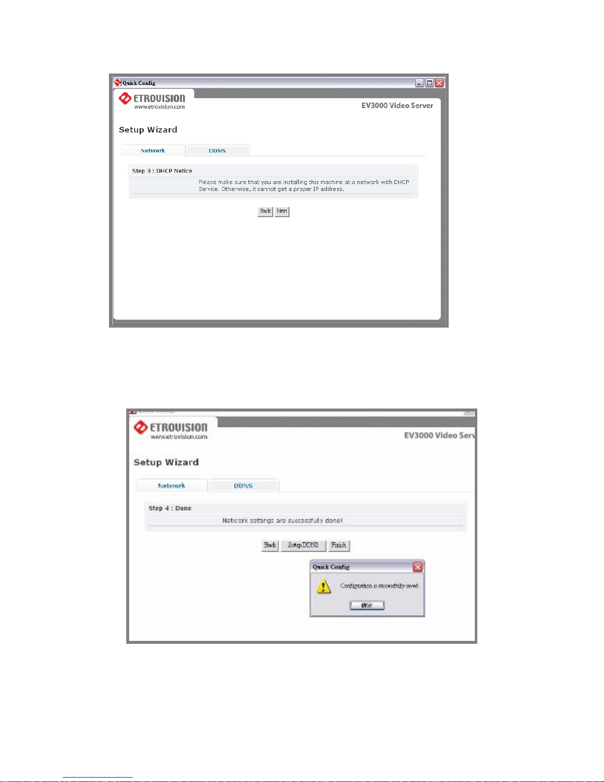
After pressing next, the setting will be saved. You can press finish or
continue to do other setting.
Page 56

Page 57
11. TROUBLESHOOTING
What If Quickconfig does not Auto run?
In some situations, Quick Config application may not auto run after
connecting to EtroLink™ via the mini USB cable.
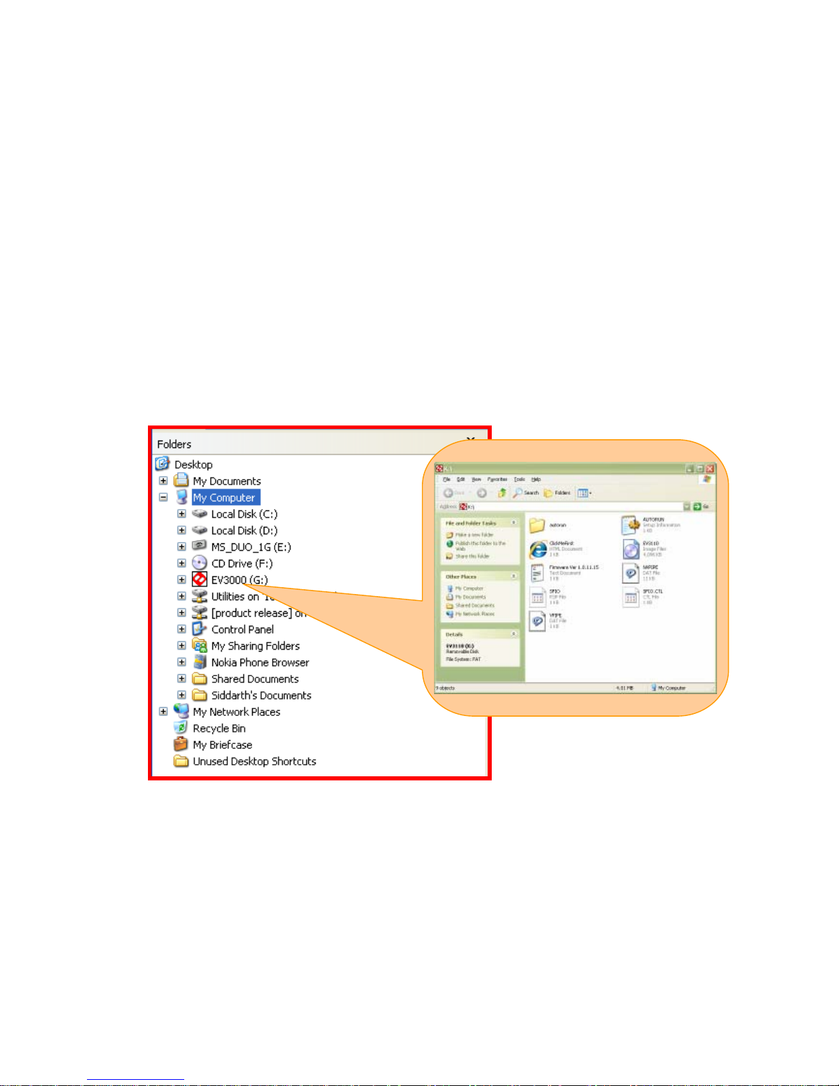
In that situation, you may open the disk drive page (the following is the
example image). The icon starts with EV should appear.
Open the folder named “autorun” . This folder contains a HTML executable
file named “autorun”. Double click the file to enab le the operation. You
will find that it is the same “Quick Config” application is running. See the
screenshots below to find that file on the disk drive.
Page 58
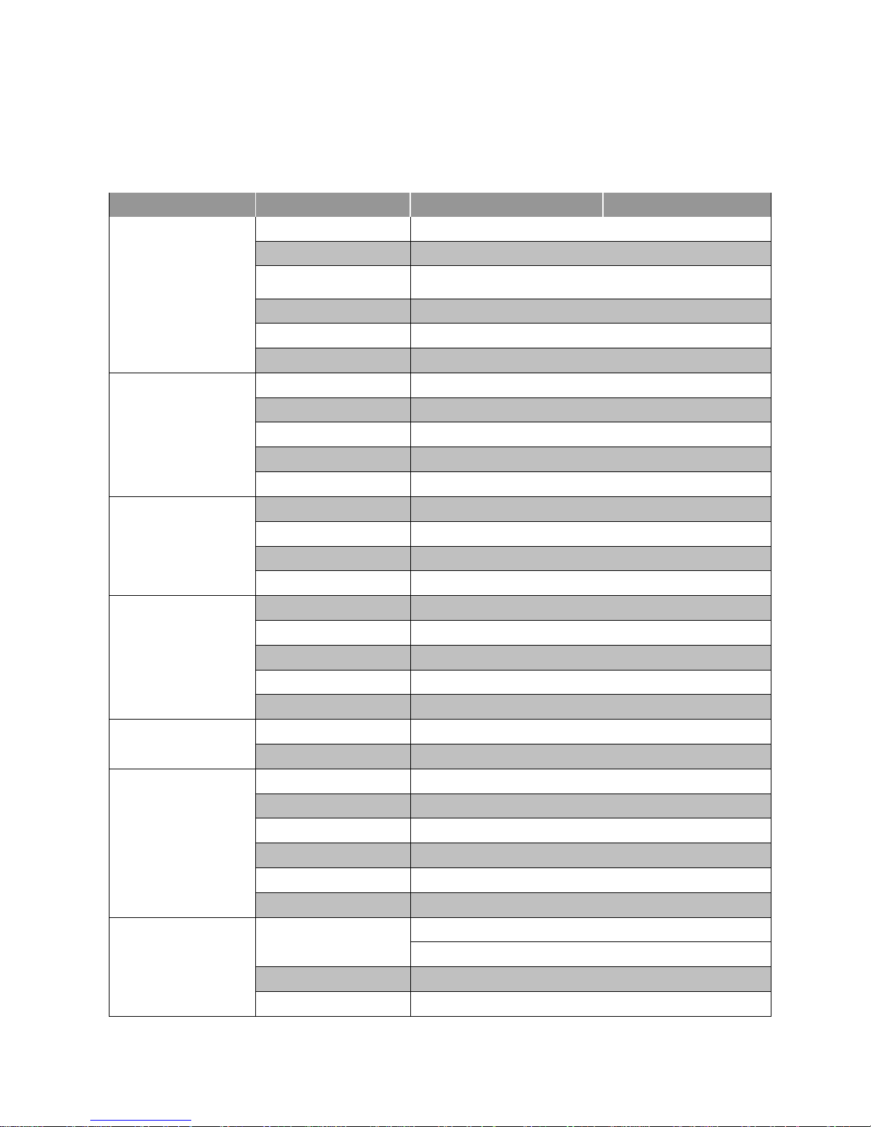
12. SPECIFICATIONS
Model EV6552A EV6552AP
Lens / Sensor
Sensor
1/4” Low-Light Sensitive CMOS
Lens Mounted
3.6mm Fixed Lens
Number of Effective Pixels (HxV)
640 x 480
Electronic Shutter
1/30~1/50,000
Gain
Auto
White Balance
Auto
Analog Video Output
Scanning System
Progressive Scan
Sync System
Internal
Resolution
640 X 480 VGA
S/N Ratio
38dB
Minimum Illumination
0.5 Lux
System
CPU
ARM 9 Based 32 Bit RISC
SDRAM
64 MB
Flash
16 MB
Embedded OS
Linux 2.6
Compression–Video / Audio
Format
M-JPEG, MPEG-4, H.264 Dual Stream Simultaneously
Frame Rate
Up to 30fps @ VGA Resolution
Video Resolution
VGA (640X480), QVGA (320X240), QQVGA (160X120)
Bit Rate
M-JPEG: 5 Video Quality Level Selectable; MPEG-4/H.264 : 64K~4Mbps
Audio
2-Way (Built-in High Sensitive MIC, Line Out Cable)
IP Network
Ethernet
10/100 Base-T
Protocol
TCP/IP, DHCP, PPPoE, HTTP, DDNS, NTP, FTP, SMTP, UDP, RTP, RTSP, 3GPP, UPnP
I/O Connector
Network
1 x RJ-45 (Female Type)
Power
1 X DC Jack (Female Type)
Audio
Line Out x 1
Alarm In/Out
Onboard Terminal Block (Digital In x 1 / Digital Out x 1)
Configuration
EtroLink™, Onboard Mini-USB Female Socket
Video Out
Onboard 2-Pin Wafer for Additional BNC Cable
Mechanical Info.
Housing Construction
Compact, Flat Design Housing
Tilt 0~90 / Pan +/-10 / Rotation +/-10
Dimension
114 (Ø) x 39 (H) mm
Weight
330g
Page 59
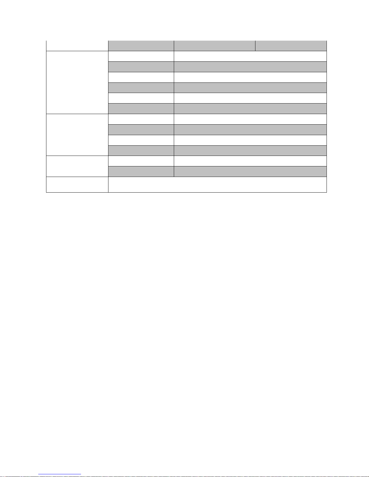
Optional
PoE (IEEE 802.3af)
N/A YES
Minimum System
Requirements
CPU
Pentinum 4, 2.4GHz and Above
Hard Disk
40 GB or Above
Memory
512 MB or Above
Operating System
Windows XP with SP2 or Above / Windows 2000 with SP4 or Above
Video Resolution
SVGA or XGA with 1024x768 Resolution
Software
DirectX 9.0C or Above
Management & Support
Configuration
EtroScan™ Utility
Integration
EtroSDK™ 3.0 Support (Windows, Linux, CGI)
Web Browser
Microsoft Internet Explorer 6.0, or Above
Security
Password Protection
Operating Environment
Temperature
0 ºC ~ 40 ºC (32 ºF ~ 104 ºF)
Humidity
20% ~ 80% RH
Supplied Accessories
Power Adapter, CD-ROM (User Manual, Free Bundle NVR), USB Cable, BNC Cable
 Loading...