

Page 1

EV6250A Series
Speed Dome IP Camera
Assembly Guide – Version 6.3
Page 2

About This Guide
Model
• EV6250A-[B, C, D] – e.g. EV6250A-CI
• EV6250A-[E, F, G] – e.g. EV6250A-GO
Purpose
The Assembly Guide provides instructions on the physical assembly and installation
for the EV6250A indoor and outdoor models.
Before Using the EV6250A
Check the PC requirements
Review the OS platform requirements
Read an special and import precautionary information
Having basic knowledge of network setup and configuration will be helpful
Disclaimer
© 2011 Etrovision Technology. All rights reserved.
Information contained in this document may be superseded by updates. No
representation or warranty is given and no liability is assumed by Etrovision
Technology with respect to the accuracy or use of the information, or infringement of
patents or other intellectual property rights. No licenses are conveyed, implicitly or
otherwise, under any intellectual property rights.
Page 3

1 EV6250A-[B, C, D] OUTDOOR HOUSING ....................................... 4
1.1 Components Checklist ................................................................................ 4
Camera Components .................................................................................. 4
Additional Components ............................................................................... 4
1.2 Required Tools & Material ........................................................................... 4
1.3 Assembly Instructions ................................................................................. 4
Bracket Setup .............................................................................................. 4
Camera Assembly Instructions .................................................................... 6
2 EV6250A-[B, C, D] INDOOR HOUSING ......................................... 16
2.1 Components Checklist .............................................................................. 16
Camera Components ................................................................................ 16
Additional Components ............................................................................. 16
2.2 Required Tools .......................................................................................... 16
2.3 Assembly Instructions ............................................................................... 16
3 EV6250A-[E, F, G] OUTDOOR HOUSING ..................................... 24
3.1 Components Checklist .............................................................................. 24
Camera Components ................................................................................ 24
Additional Components ............................................................................. 24
3.2 Required Tools & Material ......................................................................... 24
3.3 Assembly Instructions ............................................................................... 24
4 EV6250A-[E, F, G] INDOOR HOUSING ......................................... 31
4.1 Components Checklist .............................................................................. 31
Camera Components ................................................................................ 31
Additional Components ............................................................................. 31
4.2 Required Tools .......................................................................................... 31
4.3 Assembly Instructions ............................................................................... 31
5 EV6250A-[E, F, G] ID CONFIGURATION ....................................... 37
Page 4
4
1 EV6250A-[B, C, D] OUTDOOR HOUSING
1.1 Components Checklist
The packaging will include the following materials.
Camera Components
• Outer Housing
• Inner Housing (includes a camera module fixed within the housing)
• Dome Cover
• Camera
Additional Components
• Power Adapter x 1
• Product CD x 1
• Screws x 3
• Combo Cable
1.2 Required Tools & Material
• Thread seal tape
1.3 Assembly Instructions
Choose a sturdy, stable place for the camera location to avoid camera shaking
which can affect the video.
Bracket Setup
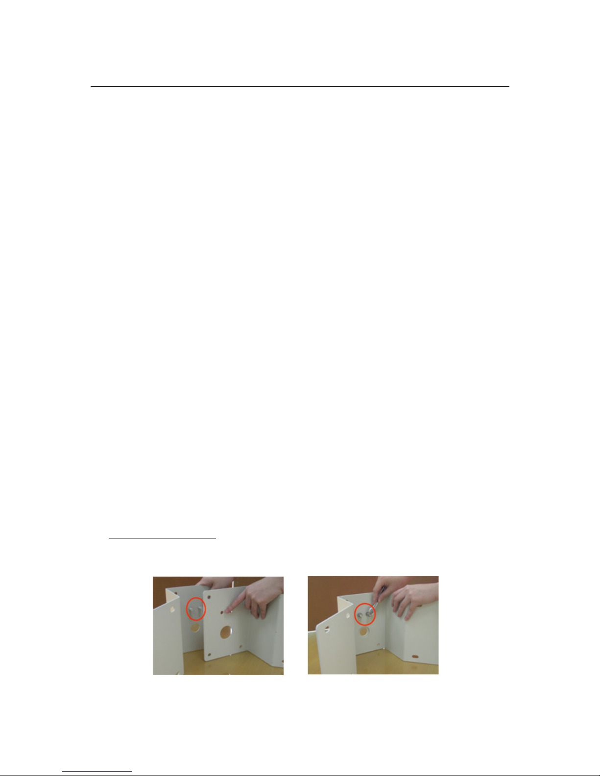
90° Corner Bracket
Combine the 2 brackets, and use the spanner to fix the screws
Page 5
5
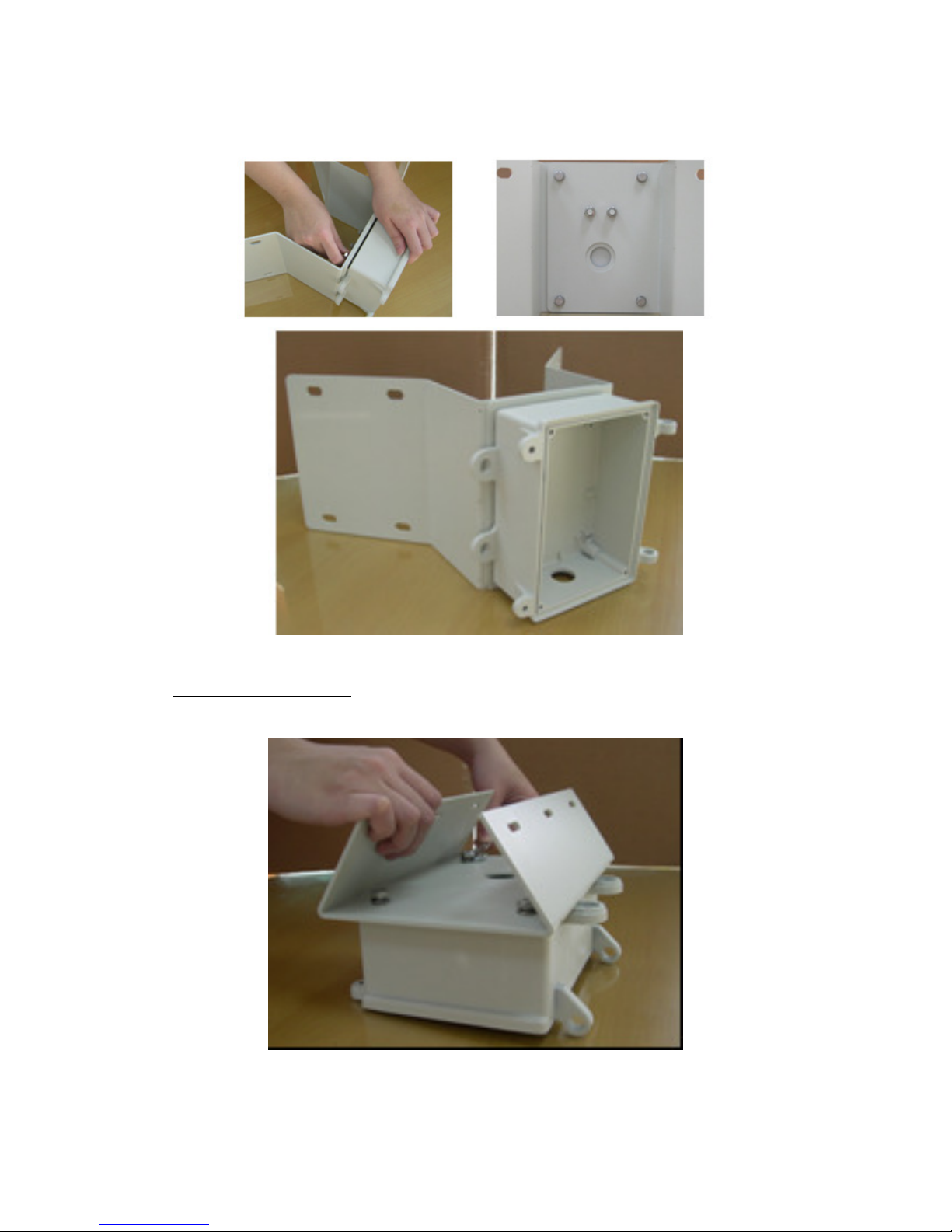
Align the screws and power box, and tighten the screws to connect the brackets
and power box.
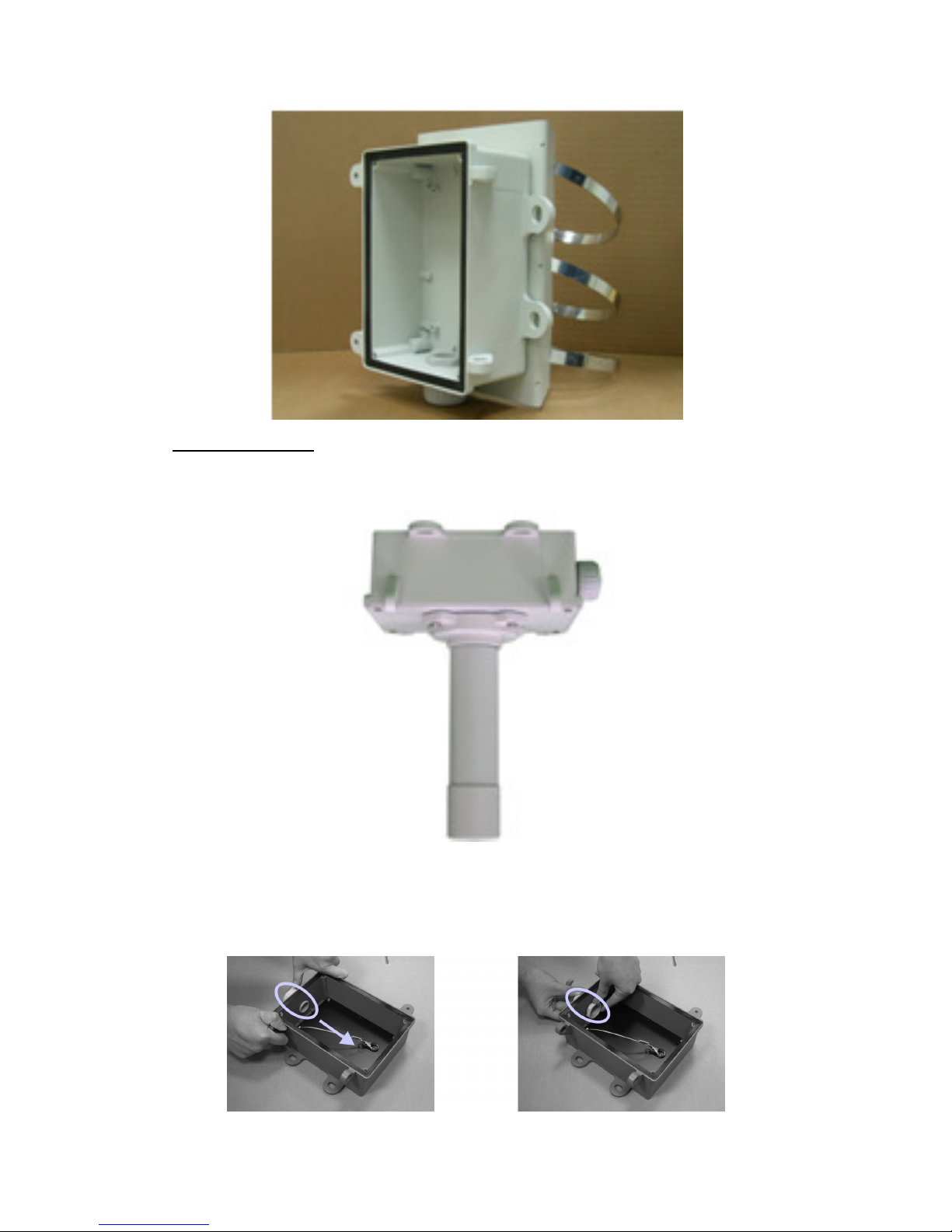
Pole Mount Bracket
Fix the bracket on the rear of the power box.
Loop the stainless steel rings through the bracket slots to complete.
Page 6
6
Pendant Mount
Fix the iron tube on the top of the power box.
Camera Assembly Instructions
Insert the plastic, cable conduit into the opening in the power box. Using the
accompanying plastic bolt, tighten bolt to secure the conduit.
Page 7
7
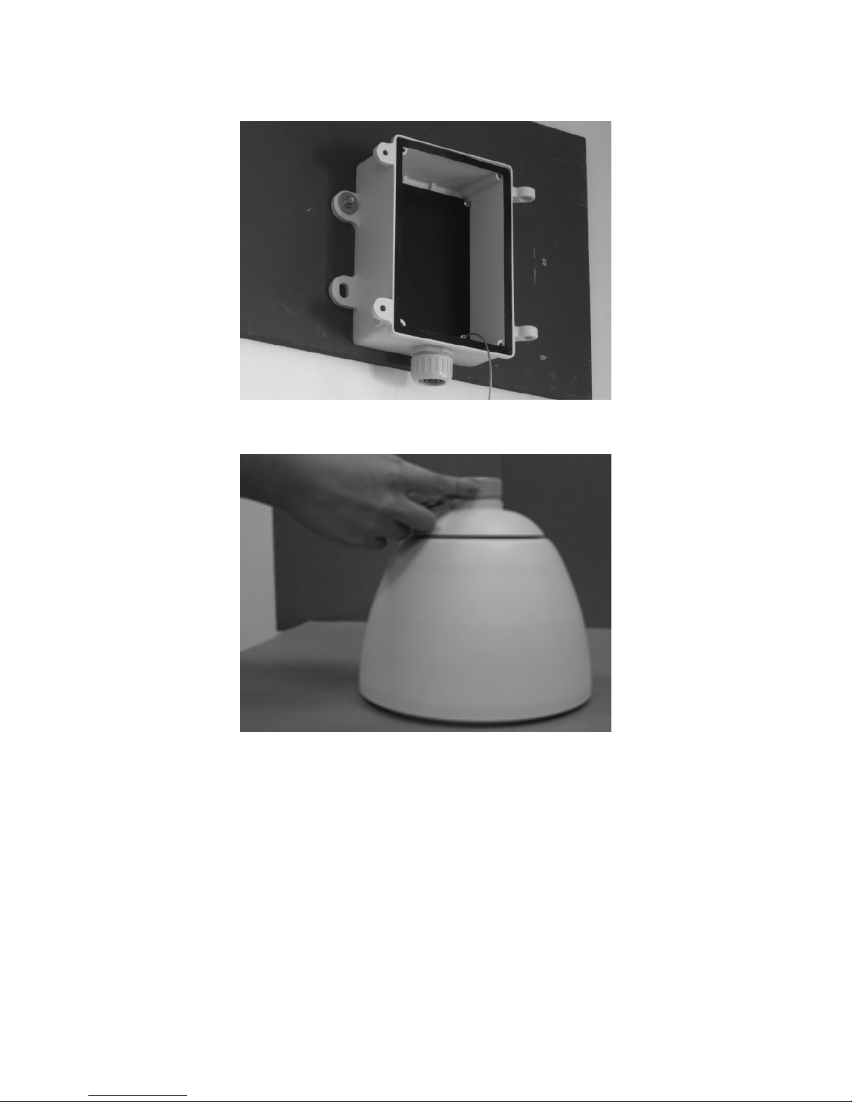
Affix the power box to the wall or mounting.
To prevent water getting into the camera housing, apply the thread seal tape to
the threading on the top of the outer housing.
NOTE: Please follow the sequence of steps as outlined below. To avoid pulling
cables loose during installation, do not connect cables to the camera board until
the bracket arm and housing have been joined together.
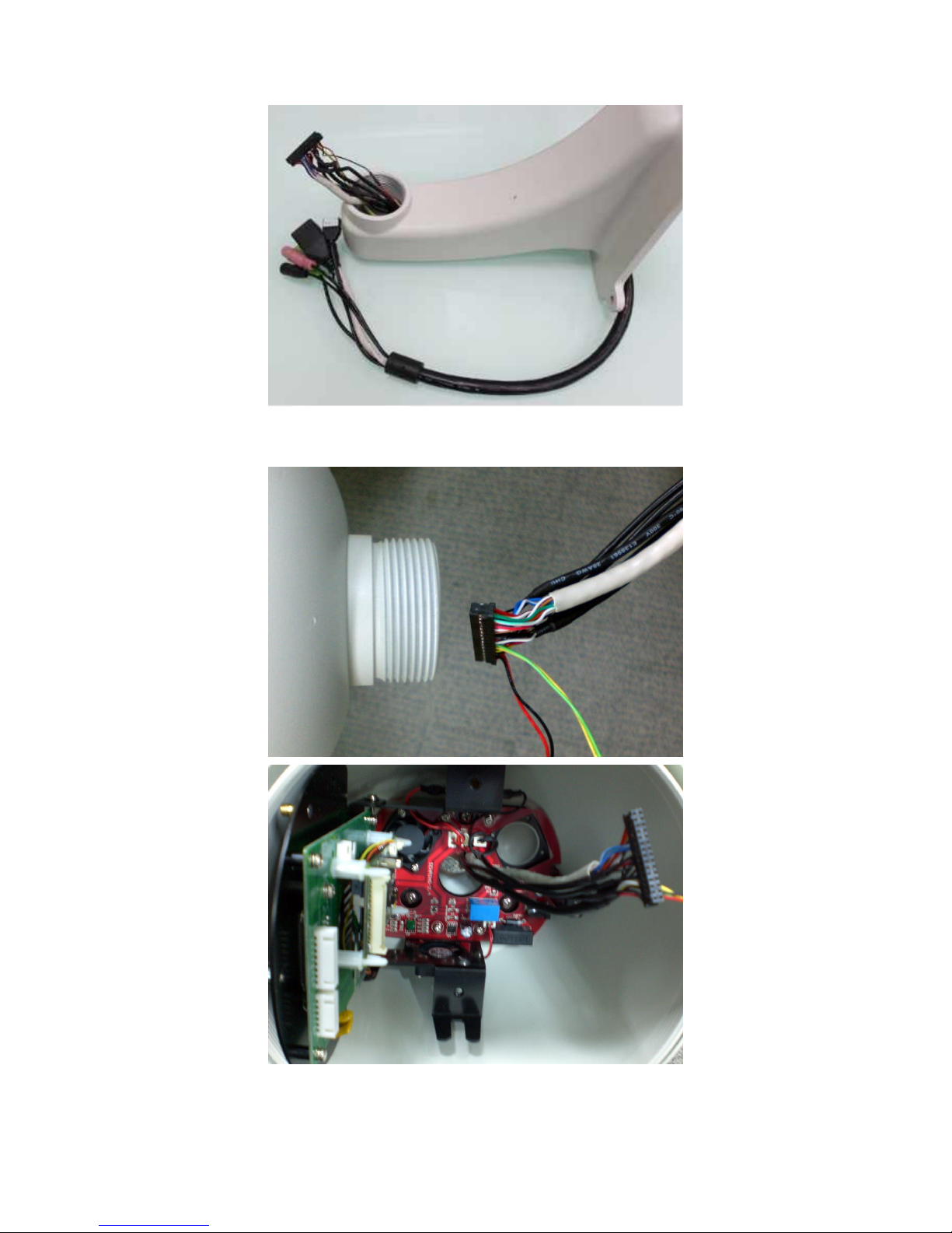
Run the combo cable through the bracket arm as seen below.
Page 8
8
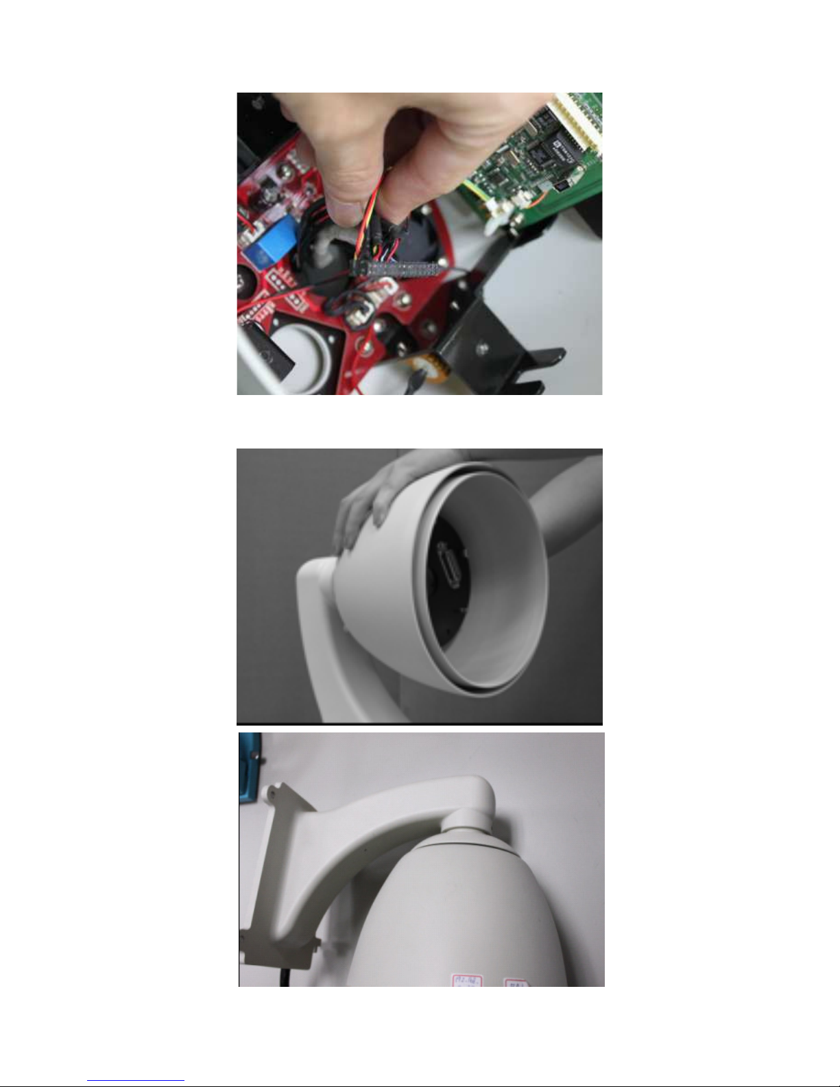
Insert the combo cable connectors into the top of the outer housing into the
camera module.
Page 9
9
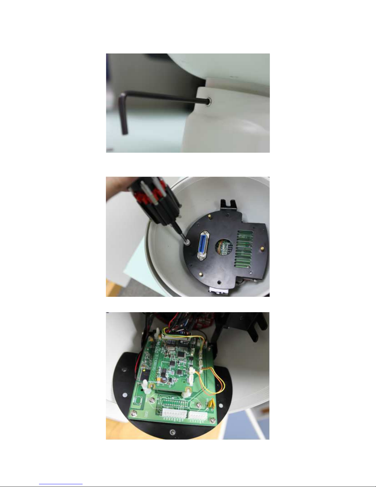
Screw the outer housing into the bracket arm by turning the housing from left to
right.
Page 10
10
Using a hex key, secure the outer housing to the bracket arm.
Within the outer housing, unscrew the fastening screw on the camera module’s
faceplate.
Gently pull open faceplate to expose the module.
Page 11
11
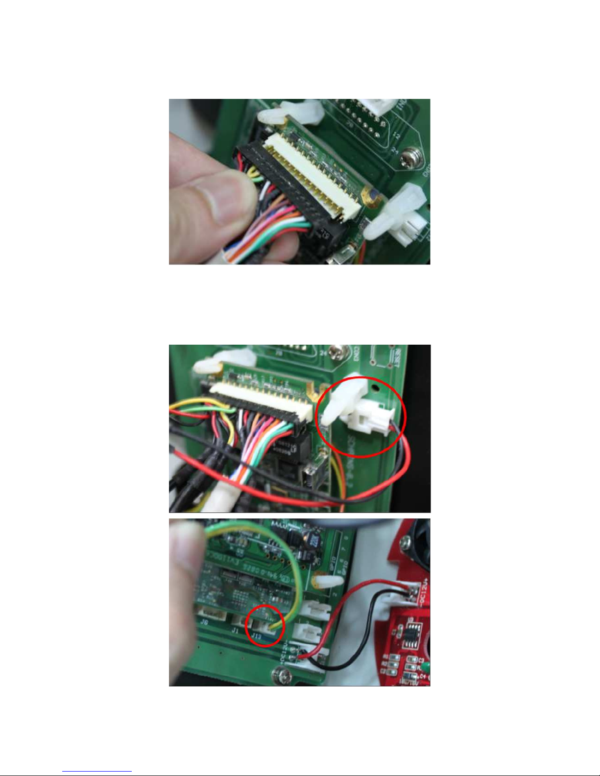
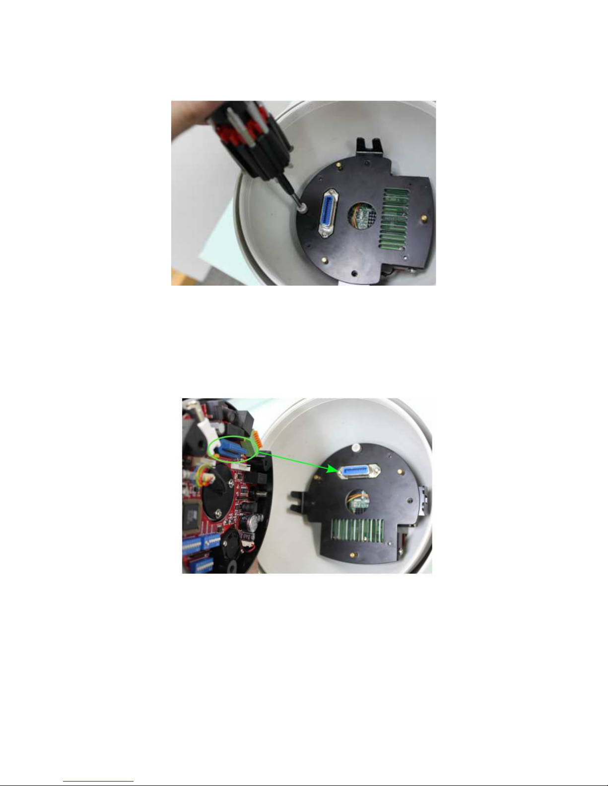
Connect the 30 pin connector to the 30 pin port. The connector has 2 slots on one
side which must be aligned with the 2 ridges on the port.
The 30 pin connector will have 2 additional connectors (both 2 pins) which must
be connected to the J12 and J13 ports. Both connector types are different, which
can be used identify whether the cabling should use the J12 or J13 port. Find the
board ports labeled J12 and J13.One side of the board has a J13 port and the other
side has a J12 port.
Page 12
12
Close the camera module and screw the fastening screw to secure the module’s
faceplate.
Remove all packaging material from the within the camera dome. Ensure all
packaging has been removed; a failure to do so will prohibit camera movement
and potentially damage the camera.
Insert the camera into the inner housing. The camera’s blue connector must be
aligned with the blue port on the camera module’s faceplate within the inner
housing.
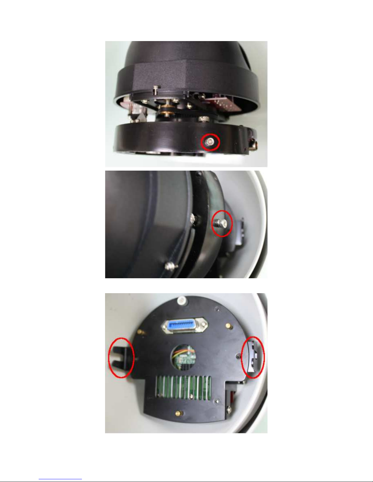
Ensure the 2 camera mounts slide into the inner housing’s camera saddle.
The 2 mounts are on the side are located at the base of the camera.
Page 13
13
The housing’s camera saddle points are highlighted below.
Page 14
14
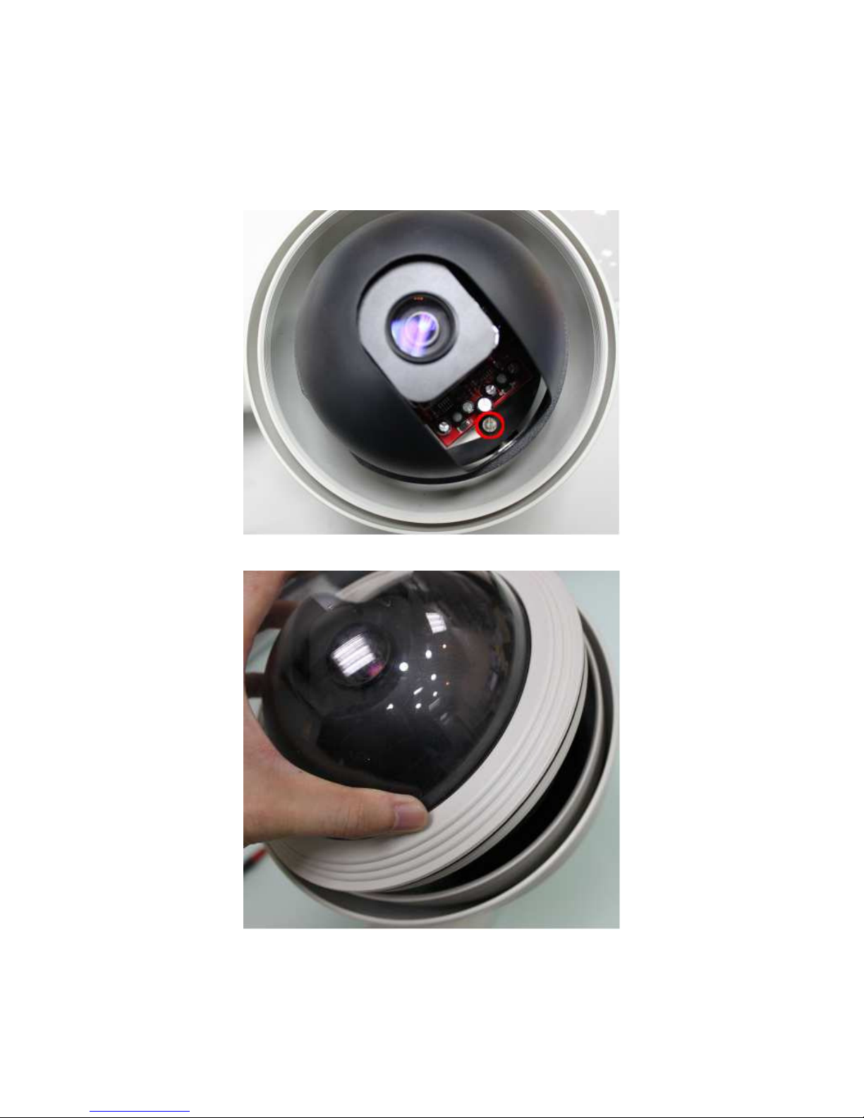
While not pushing too firmly, push down to make sure the connector is inserted
into the port. Verify the camera mounts are settled properly into the saddle.
Spin the camera dome to find the 2 slotted screw heads on the base inside of the
camera; using a slotted screwdriver tighten the screws to secure the camera to the
inner housing camera plate.
Screw the dome cover into the inner housing
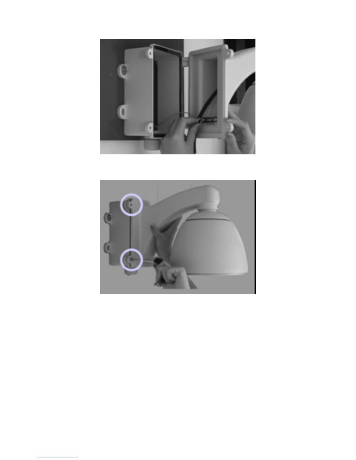
Set the bracket arm into the power box hinges and hook the power box safety
clasp to the loop in the base of the bracket arm.
Page 15
15
Run the combo cable through the power box cable conduit.
Using the two screws provided, screw shut bracket arm/power box housing.
Connect the power cable to the combo cable power connector.
The camera will perform a test scan movement during startup. If the camera
doesn’t move or there is no power, then likely the camera module cabling needs
to be verified. Unplug the power before disassembling and verifying cabling.
Page 16

16
2 EV6250A-[B, C, D] INDOOR HOUSING
2.1 Components Checklist
The packaging will include the following materials.
Camera Components
• Outer Housing
• Inner Housing (includes a camera module fixed within the housing)
• Dome Cover
• Camera
Additional Components
• Power Adapter x 1
• Product CD x 1
• Anchor Clips x 3
• Screws x 3
• Combo Cable
2.2 Required Tools
• Slotted Screwdriver
2.3 Assembly Instructions
Remove the contents from packaging, but don’t remove the plastic covering from
the dome cover until assembly and installation has been completed. This helps
protect the cover from scratches, fingerprints, etc.
Unplug the power and any other cabling from the combo cable if applicable.
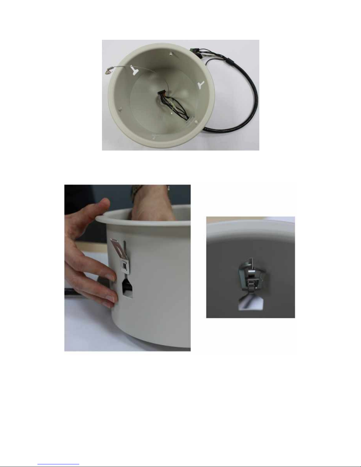
Insert the combo cable into the outer housing via the cable conduit on the side of
the housing. The 30 pin connector cable can be folded to get the connector
through the conduit.
Page 17
17
Slide the anchor clips into the outer housing slots and secure the clasp. A gap
should exist between the clip and the outer housing rim; this gap is where the
clip will rest on the ceiling for support.
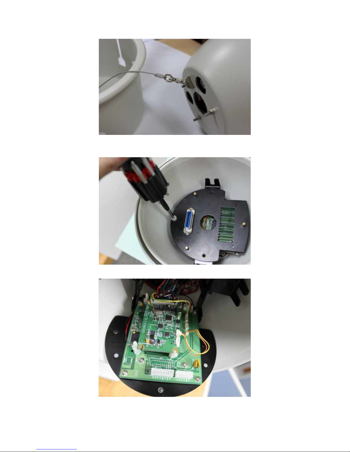
Using the securing cable within the outer housing, secure the inner housing to
the outer housing by affixing the securing cable to the loop on top of the inner
housing. The securing cable will prevent the inner housing from falling during
installation.
Page 18
18
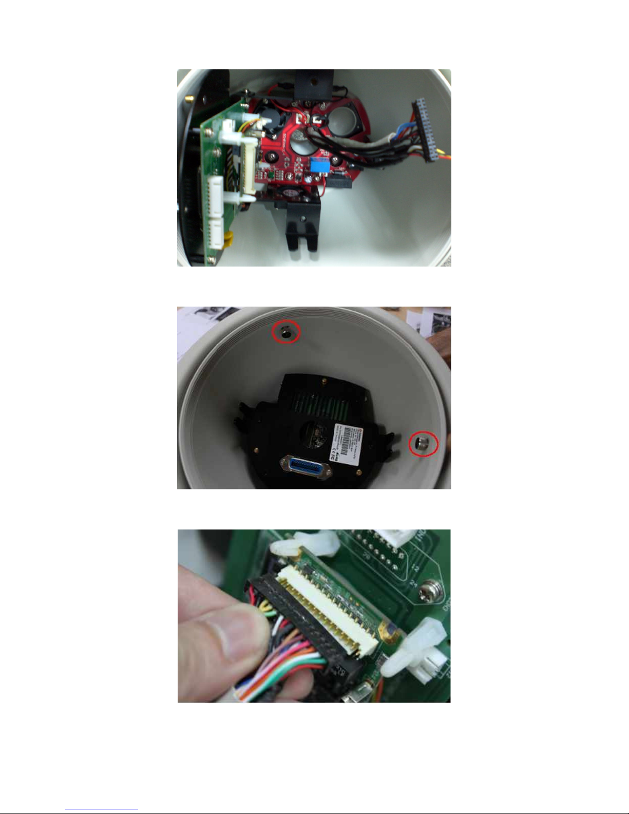
Within the inner housing, unscrew the fastening screw on the camera module’s
faceplate.
Gently pull open faceplate to expose the module.
Insert the combo cable into the top of the inner housing into the camera module.
Page 19
19
Place the inner housing into the outer housing. Secure the inner housing to the
outer using the 3 screws provided.
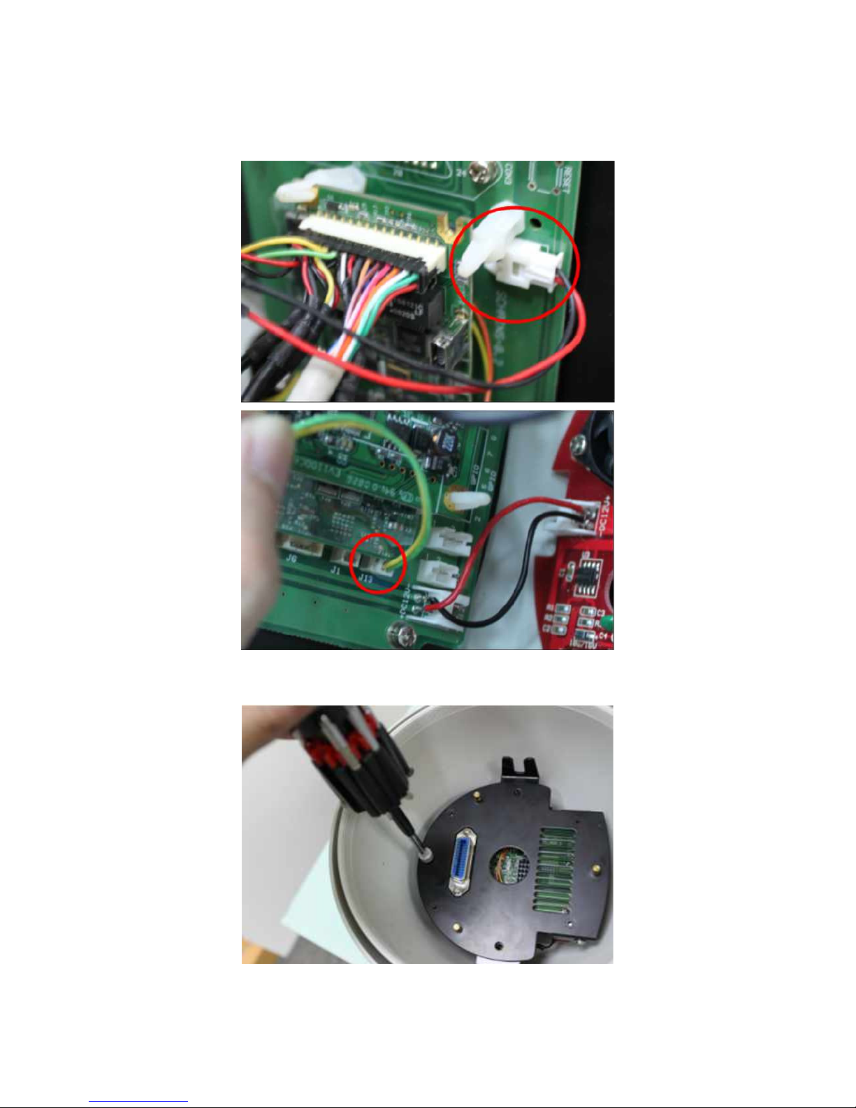
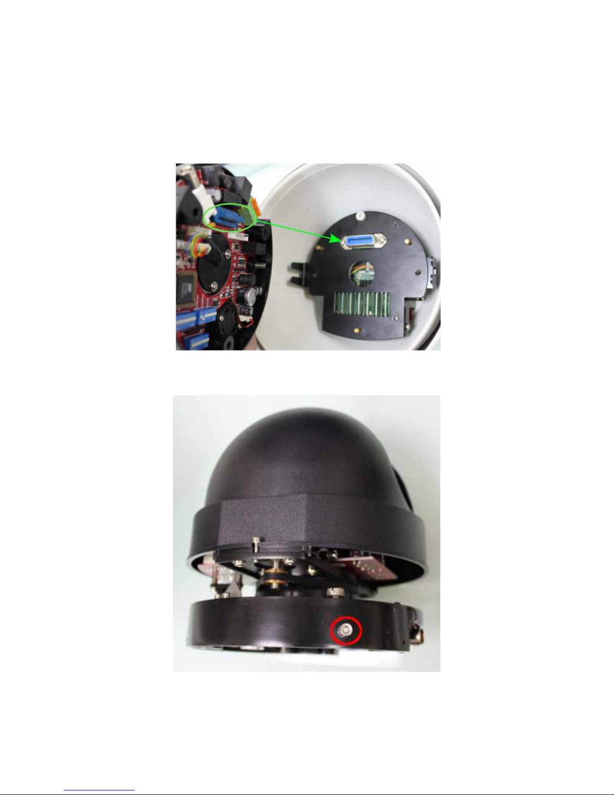
Connect the 30 pin connector to the 30 pin port. The connector has 2 slots on one
side which must be aligned with the 2 ridges on the port
The 30 pin connector will have 2 additional connectors (both 2 pins) which must
be connected to the J12 and J13 ports. Both connector types are different, which
Page 20
20
can be used identify whether the cabling should use the J12 or J13 port. Find the
board ports labeled J12 and J13.One side of the board has a J13 port and the other
side has a J12 port.
Close the camera module and screw the fastening screw to secure the module’s
faceplate.
Place the inner housing into the outer housing.
Page 21
21
Remove all packaging material from the within the camera dome. Ensure all
packaging has been removed; a failure to do so will prohibit camera movement
and potentially damage the camera.
Insert the camera into the inner housing. The camera’s blue connector must be
aligned with the blue port on the camera module’s faceplate within the inner
housing.
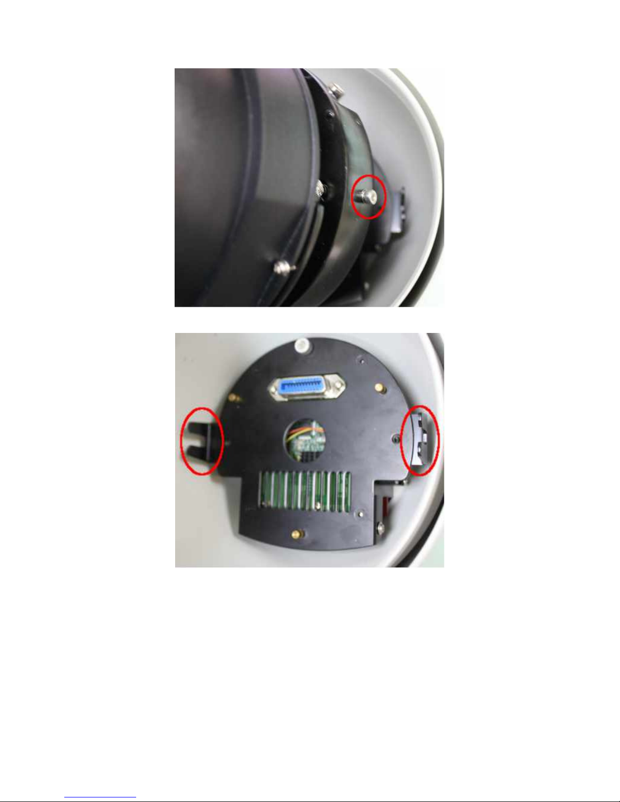
Ensure the 2 camera mounts slide into the inner housing’s camera saddle.
The 2 mounts are on the side are located at the base of the camera.
Page 22
22
The housing’s camera saddle points are highlighted below.
Push down gently to insert the connector into the port and verify the pins have
settled properly into the mounts.
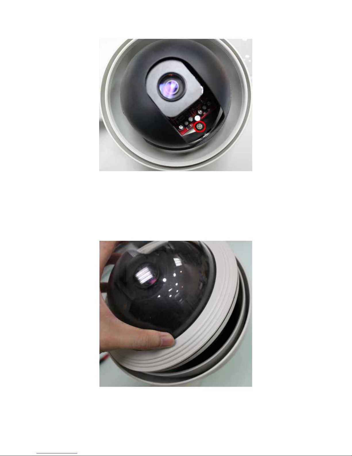
Spin the camera dome to find the 2 slotted screw heads on the base inside of the
dome camera. Using a slotted screwdriver, tighten the screws to secure the dome
camera to the inner housing camera faceplate.
Page 23
23
The camera will perform a test scan movement during startup. If the camera
doesn’t move or there is no power, then likely the camera module cabling needs
to be verified. Unplug the power before disassembling and verifying cabling.
Slide the camera into the hole in the ceiling. Make sure the clips are set back far
enough from the outer housing lip and ceiling to catch the ceiling and prevent
the camera from falling through the hole.
Screw the dome cover into the inner housing.
Connect the power cable to the combo cable power connector.
Page 24
24
3 EV6250A-[E, F, G] OUTDOOR HOUSING
3.1 Components Checklist
The packaging will include the following materials.
Camera Components
• Power Junction Box
• Tube Arm
• Outer Housing
• PTZ Camera
• Plastic Camera Cover
Additional Components
• RS-485/DI-DO Adapter Cable
• Product CD x 1
• Screws x 4
• Screws x 4
• Hex x 2
3.2 Required Tools & Material
• May require screws/bolts/anchors for mounting
3.3 Assembly Instructions
: Insure that electrical power has been disconnected before beginning the
installation.
Choose a sturdy, stable place for the camera location to avoid camera shaking
which can affect the video.
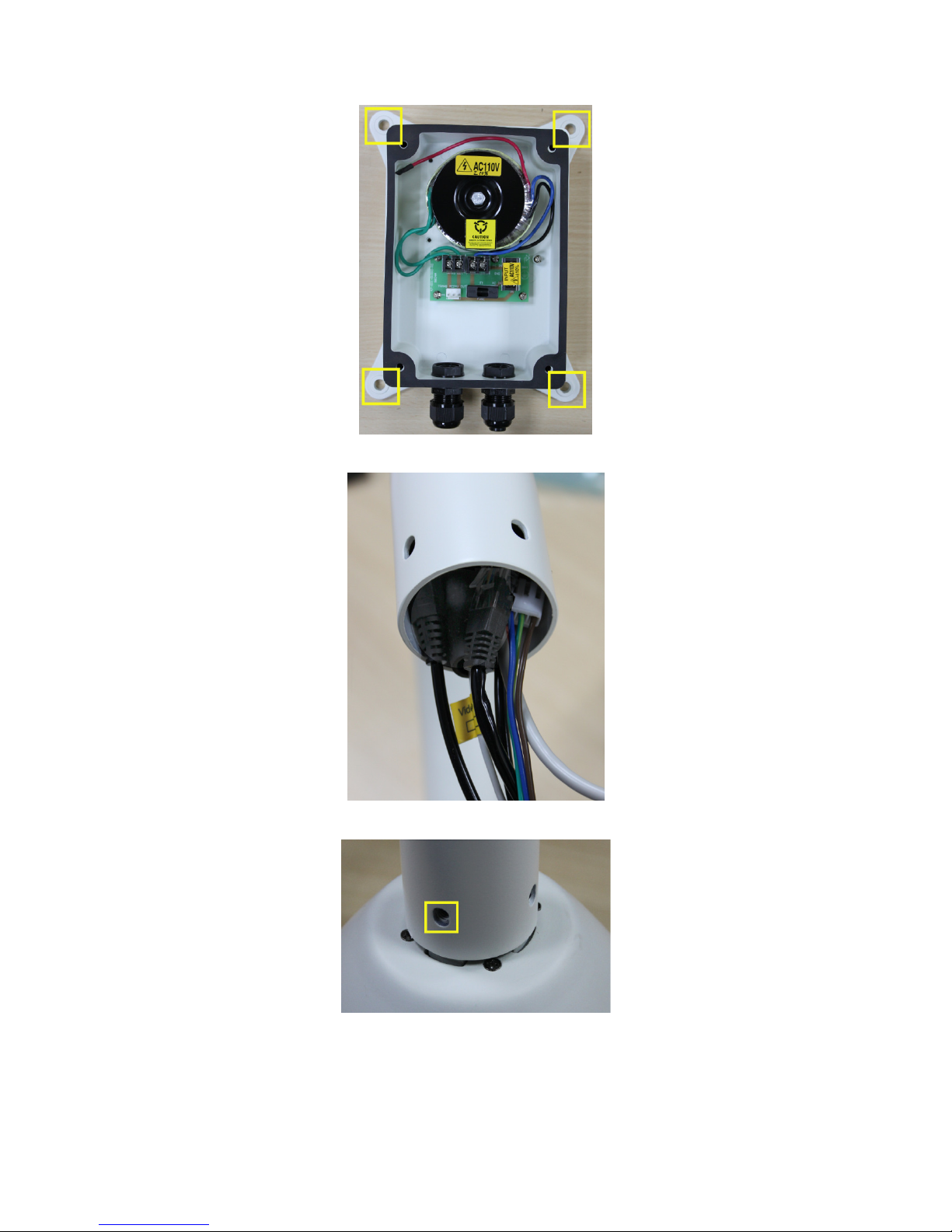
Drill pilot holes and affix the junction box to the installation surface.
Bolts/screws, washers, etc may be need to be procured.
Page 25
25
Run the cabling from the dome housing into the arm tube.
Using the 4 screws, secure the tube and dome housing.
Run cabling into the junction box.
Page 26
26
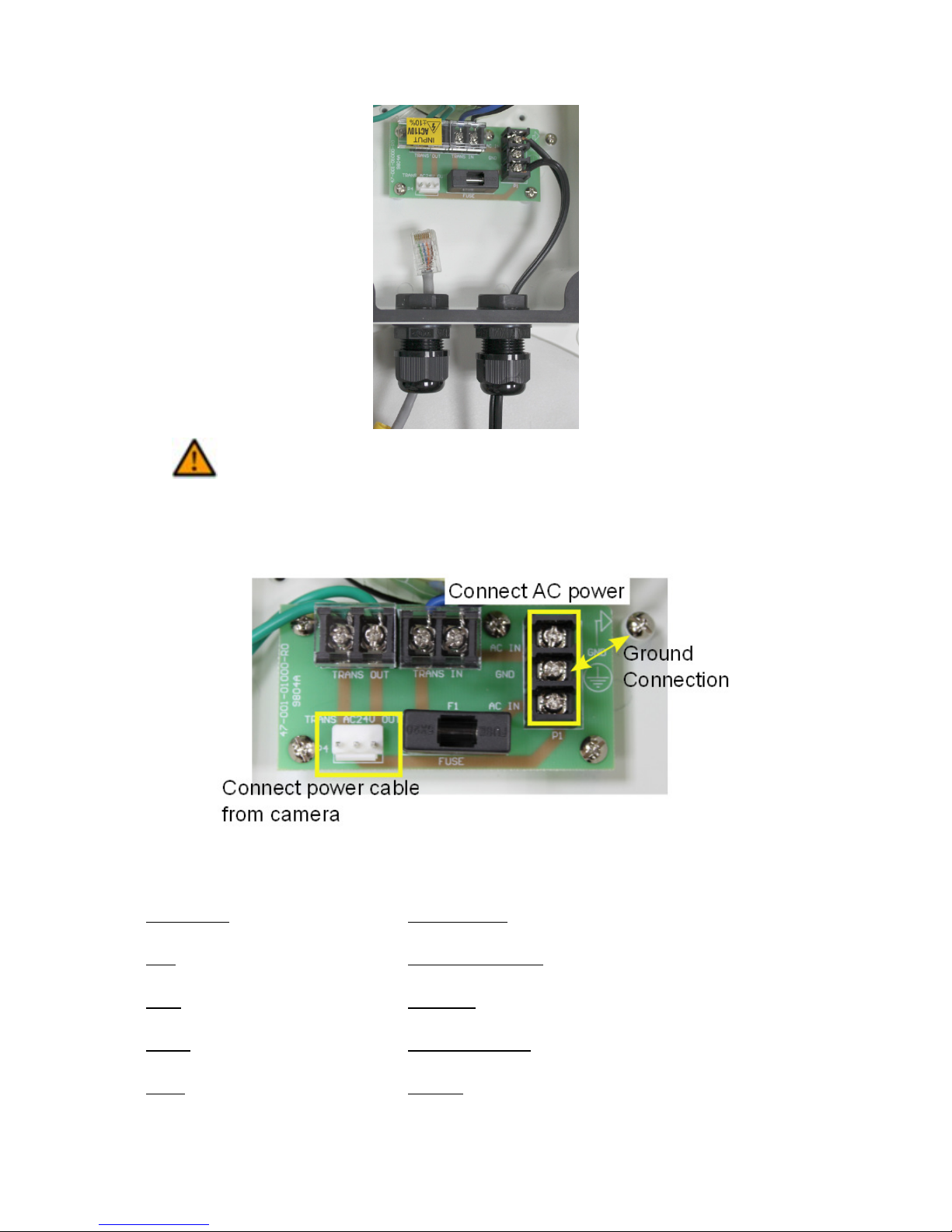
: Insure electrical power has been disconnected before proceeding with the
electrical wiring and junction box configuration.
Connect AC power to AC IN, ground, and camera power cable to power block
terminal.
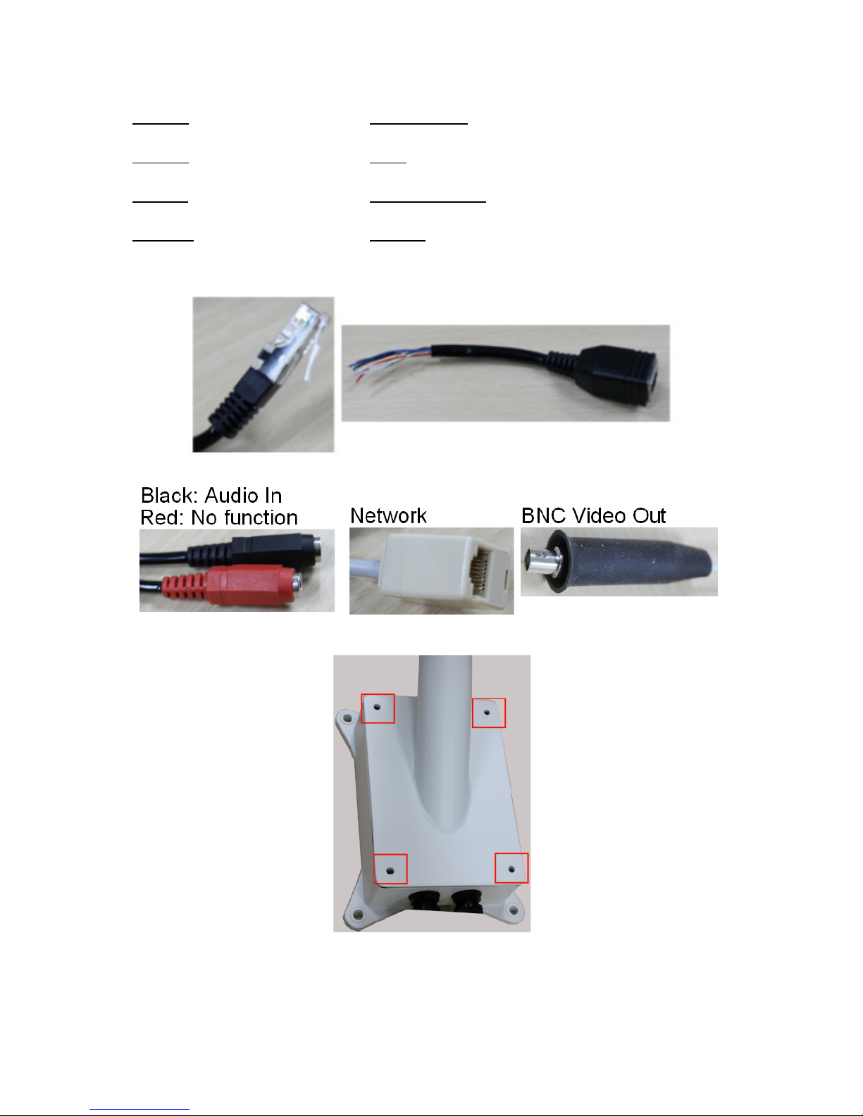
Connect remaining cabling. The table below describes the DI/DO & RS485
cabling using the adapter.
Function Line Color
DI- Orange/White
DI+ Orange
DO+ Green/White
DO-
Green
Page 27
27
NONE Blue/White
NONE Blue
RS485- Brown/White
RS485+ Brown
The adapter should be connected to the black line.
Using the 4 screws provided, secure tube arm to the junction box.
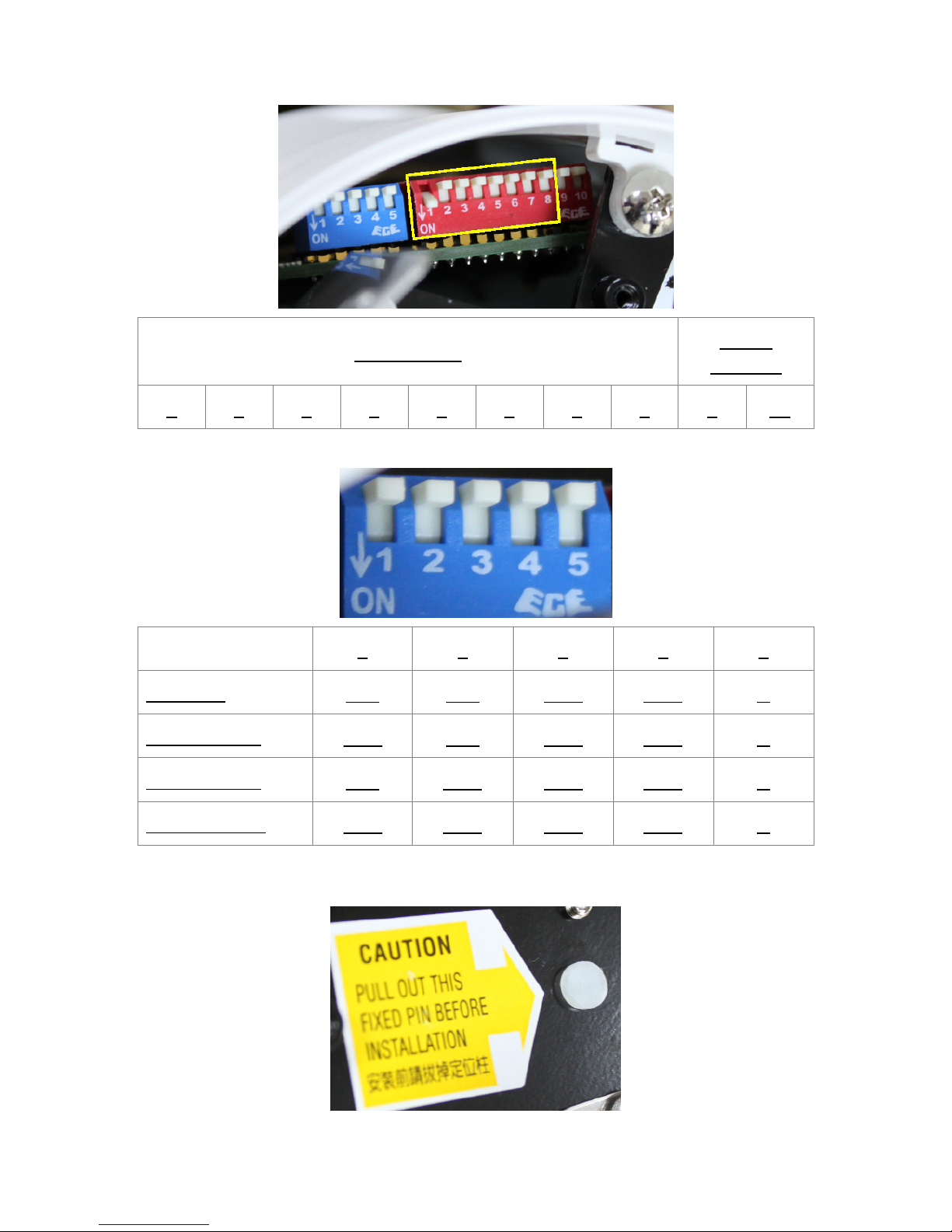
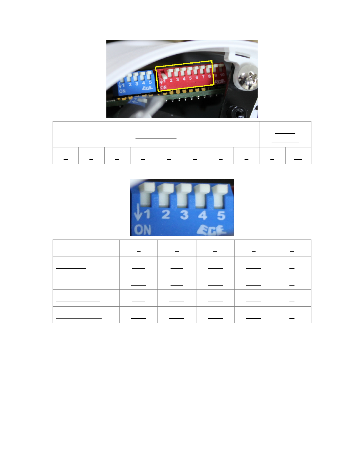
If the device address requires modification, adjust the dip switch settings located
on the base of the PTZ camera. Refer to section 5 for dip switch settings.
Page 28
28
Address ID
Don’t
Change
1 2 3 4 5 6 7 8 9 10
Protocol and baud rate can be changed using the blue panel dip switch.
1 2 3 4 5
Eyeview
ON ON OFF OFF X
Pelco P-9600
OFF ON OFF OFF X
Pelco P-4800
ON OFF OFF OFF X
Pelco D-2400
OFF OFF OFF OFF X
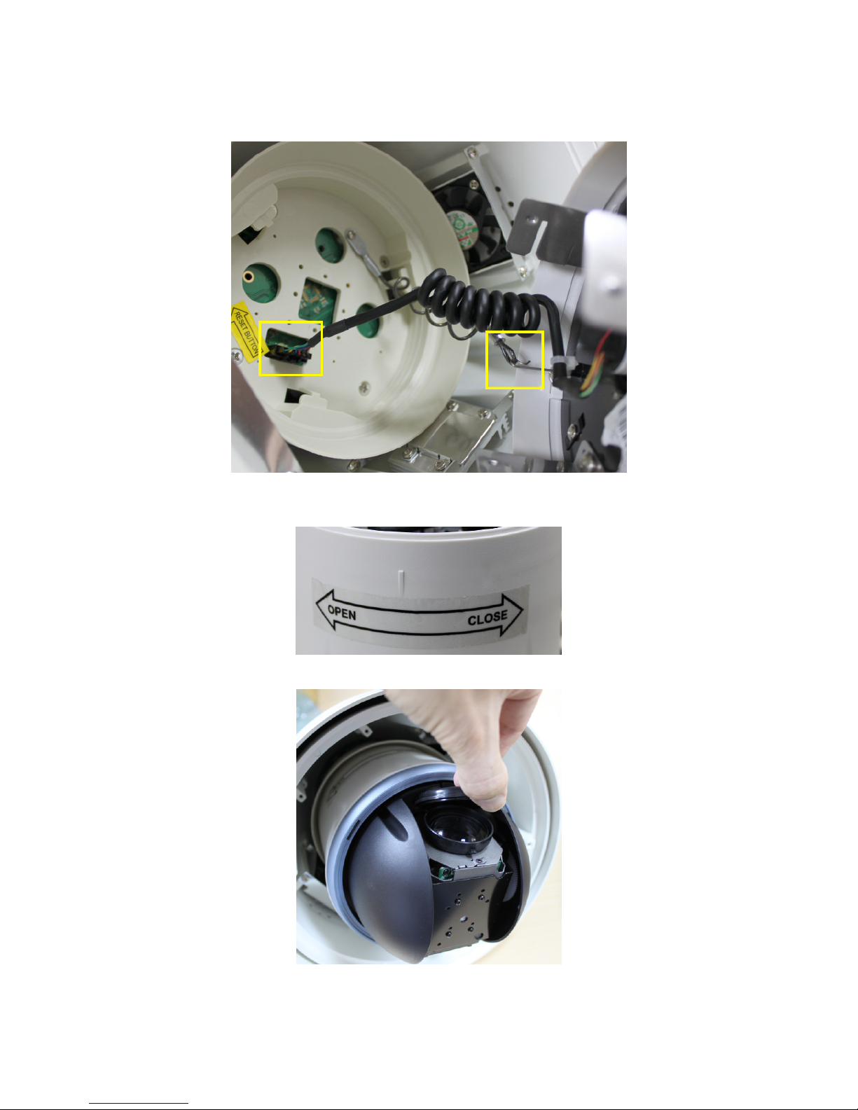
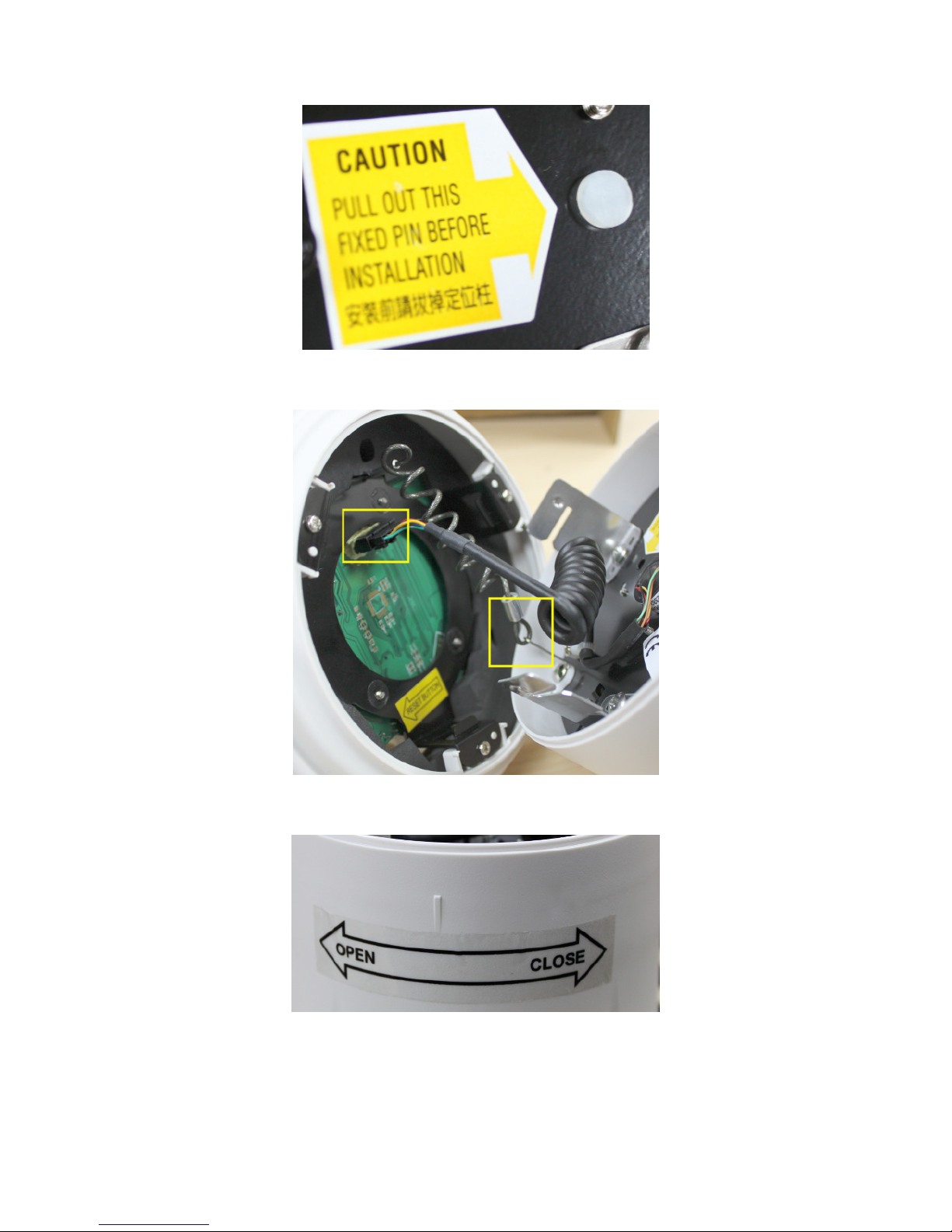
Before installing the PTZ camera into the dome housing, remove the plastic pin
from the base of the PTZ camera.
Page 29
29
Connect the safety catch wire from the dome house to the hook PTZ camera. Also
connect the camera’s 6-pin connector to the dome housing.
Insert the camera into the dome housing, turn the camera in the direction of
“CLOSE” label to lock the camera into the dome housing.
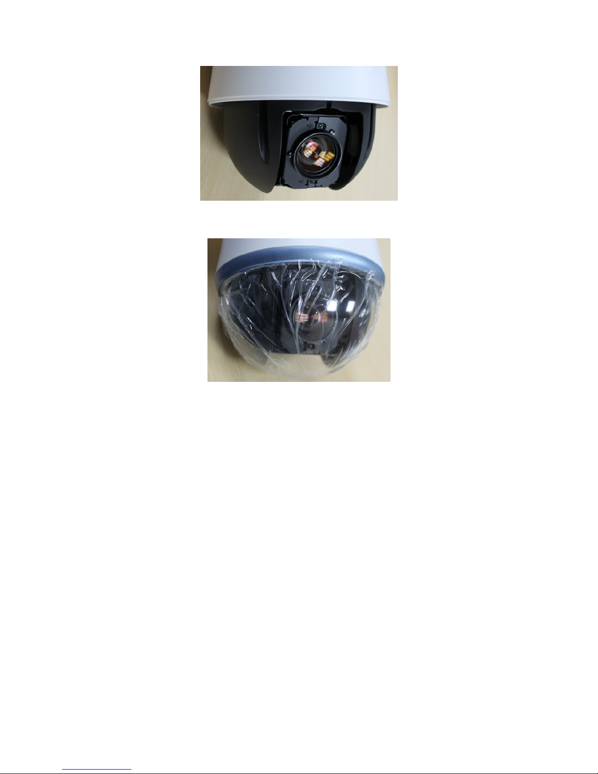
Remove the lens cover.
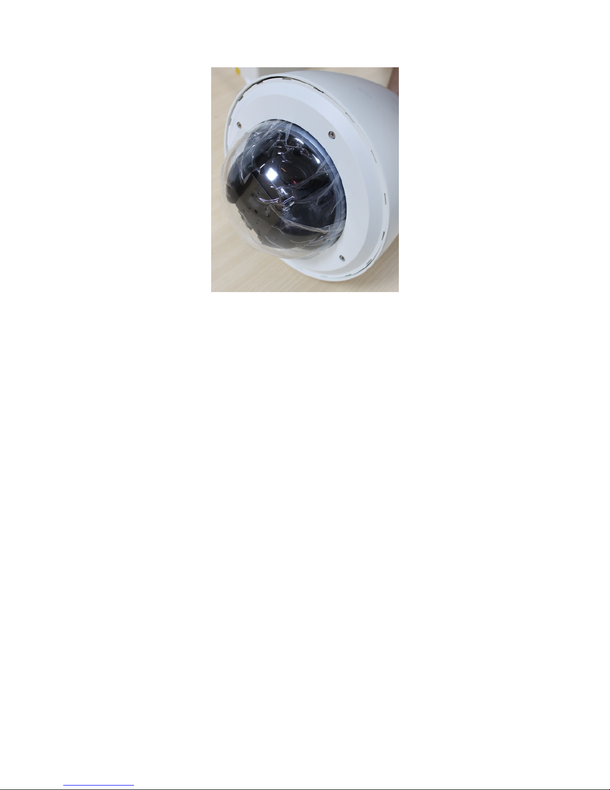
Affix the plastic dome cover on to the bottom on the dome housing, and remove
the protective plastic covering.
Page 30
30
Page 31

31
4 EV6250A-[E, F, G] INDOOR HOUSING
4.1 Components Checklist
The packaging will include the following materials.
Camera Components
• Camera Base
• PTZ Camera
• Combo Cable
• Plastic Cover
Additional Components
• Power Adapter x 1
• Product CD x 1
• Screws, washers and nuts x 3
• Combo Cable
• Hanging bracket with drill hole template
4.2 Required Tools
• Phillips screwdriver
4.3 Assembly Instructions
Decide where the speed dome camera will be mounted, and cut a hole if
necessary.
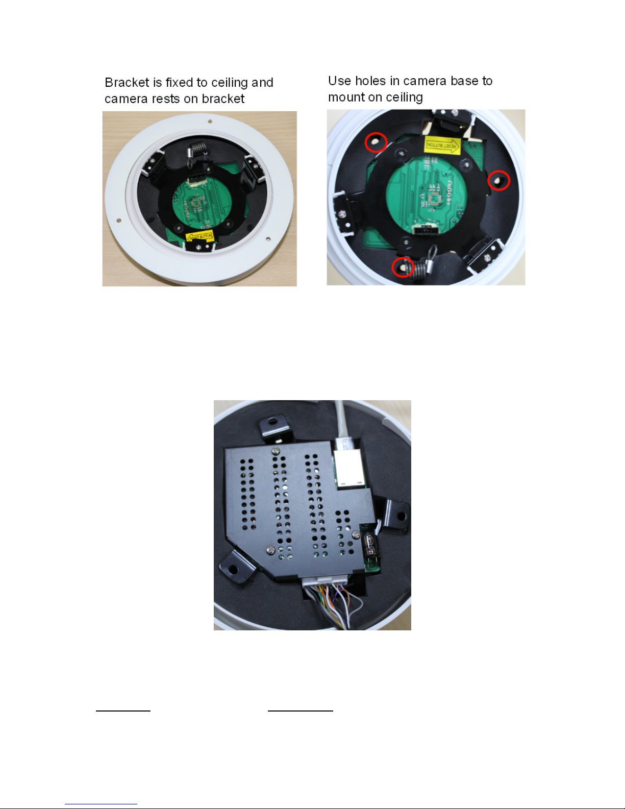
The camera can be directly mounted to the ceiling, or the hanging mounting
bracket can be used to the included hanging bracket.
Page 32
32
If the camera will be mounted in the hanging bracket, then use the drill hole
template to drill pilot holes. The included screws, washers & nuts can be used for
mounting the hanging bracket.
Otherwise drill pilot holes to mount camera directly on the ceiling.
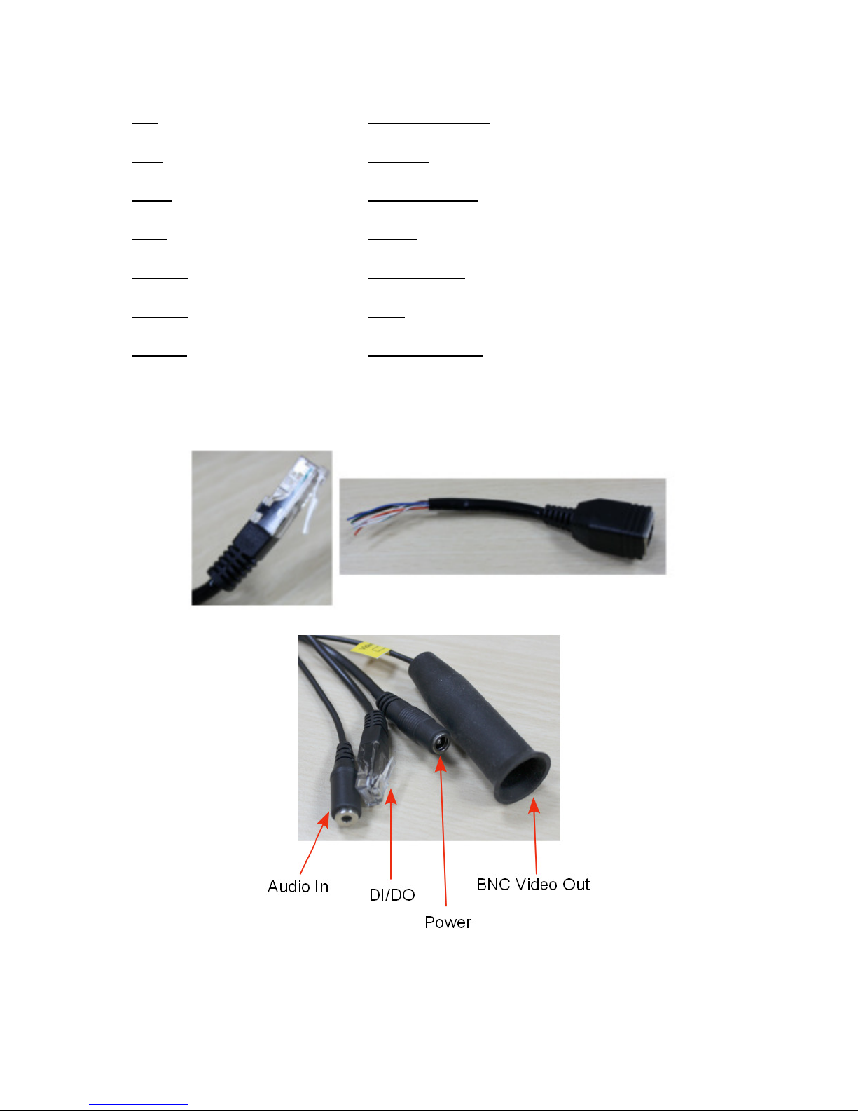
Connect the combo cable and network cable. The foam padding can be pushed
down to insert the cabling.
Connect the combo cable with respective cabling (e.g. DI/DO, audio in).
Connect remaining cabling. The table below describes the DI/DO & RS485
cabling using the adapter.
Function Line Color
Page 33
33
DI- Orange/White
DI+ Orange
DO+ Green/White
DO- Green
NONE Blue/White
NONE Blue
RS485- Brown/White
RS485+ Brown
The adapter should be connected to the black line.
If the device address requires modification, adjust the dip switch settings located
on the base of the PTZ camera. Refer to section 5 for dip switch settings.
Page 34
34
Address ID
Don’t
Change
1 2 3 4 5 6 7 8 9 10
Protocol and baud rate can be changed using the blue panel dip switch.
1 2 3 4 5
Eyeview
ON ON OFF OFF X
Pelco P-9600
OFF ON OFF OFF X
Pelco P-4800
ON OFF OFF OFF X
Pelco D-2400
OFF OFF OFF OFF X
Before installing the PTZ camera into the dome housing, remove the plastic pin
from the base of the PTZ camera.
Page 35
35
Connect the safety catch wire from the dome house to the hook PTZ camera. Also
connect the camera’s 6-pin connector to the dome housing.
Insert the camera into the dome housing, turn the camera in the direction of
“CLOSE” label to lock the camera into the dome housing.
Remove the lens cover.
Page 36
36
Affix the plastic dome cover on to the bottom on the dome housing, and remove
the protective plastic covering.
Page 37
37
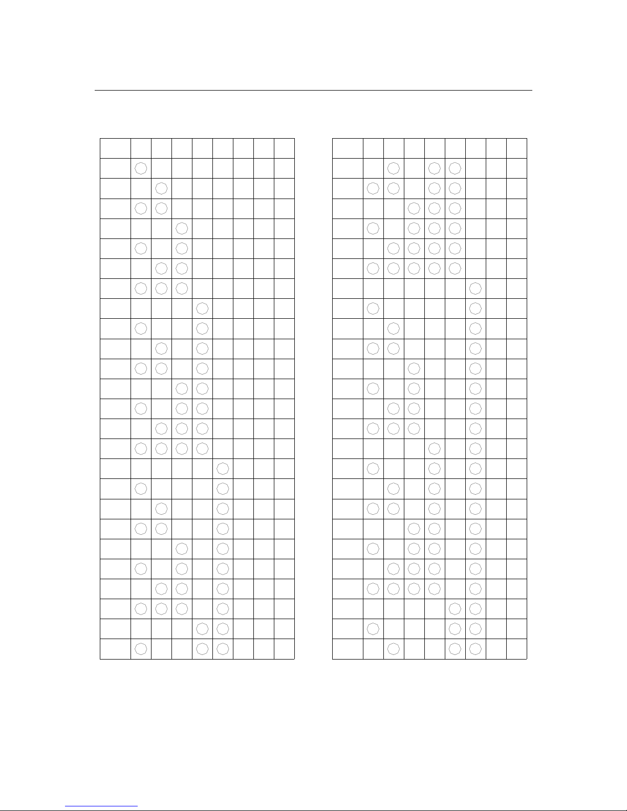
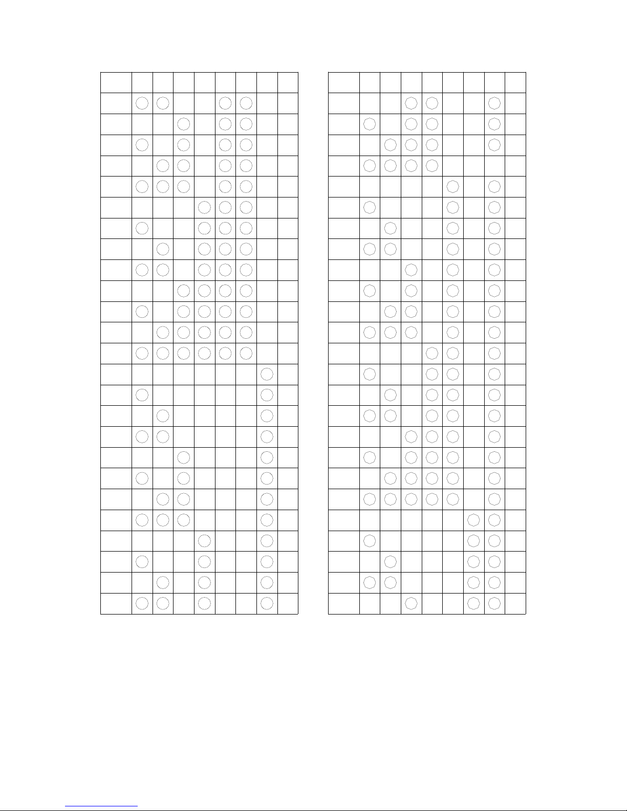
5 EV6250A-[E, F, G] ID CONFIGURATION
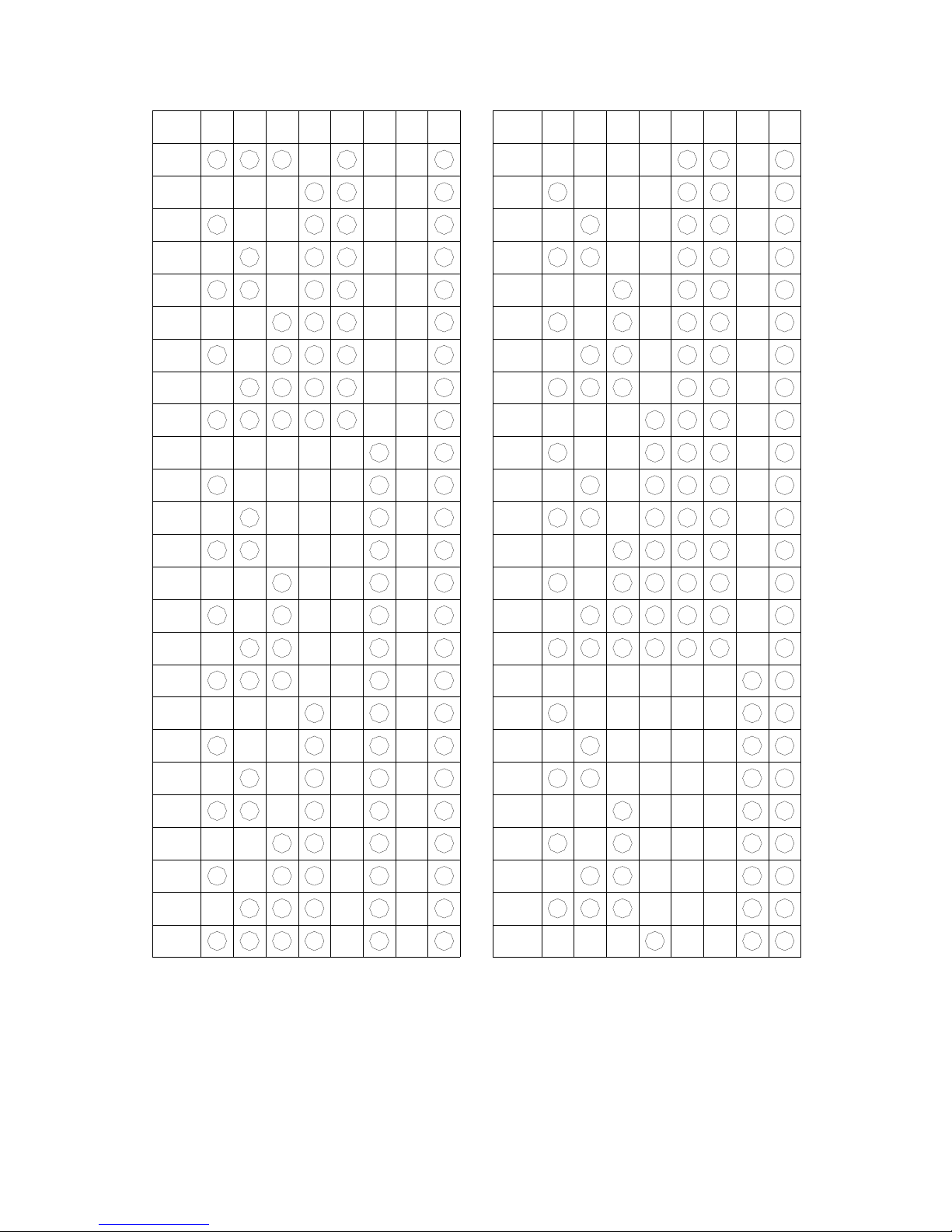
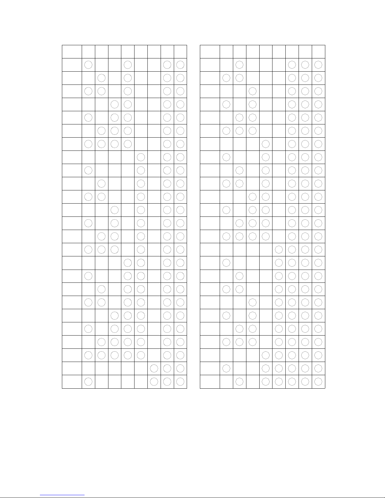
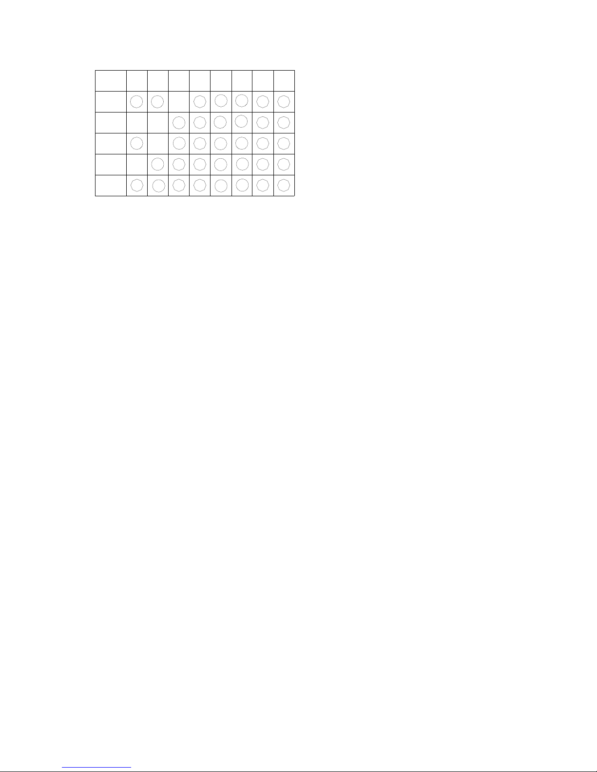
Symbol “○” in the following tables denote setting “ON”
1
2 3 4 5 6 7 8
1
2
3
4
5
6
7
8
9
10
11
12
13
14
15
16
17
18
19
20
21
22
23
24
25
4
50
44
47
49
48
46
45
41
43
42
40
39
27
33
36
37
38
34
35
30
31
32
29
28
26
213 65 7 8
Page 38
38
1
2 3 4 5 6 7 8
51
52
53
54
55
56
57
58
59
60
61
62
63
64
65
66
67
68
69
70
71
72
73
74
75
4
100
94
97
99
98
96
95
91
93
92
90
89
77
83
86
87
88
84
85
80
81
82
79
78
76
213 65 7 8
Page 39
39
1
2 3
4 5
6
7
8
151
152
153
154
155
156
157
158
159
160
161
162
163
164
165
166
167
168
169
170
171
172
173
174
175
4
200
194
197
199
198
196
195
191
193
192
190
189
177
183
186
187
188
184
185
180
181
182
179
178
176
213 6
5 7
8
Page 40
40
1
2 3
4 5
6
7
8
201
202
203
204
205
206
207
208
209
210
211
212
213
214
215
216
217
218
219
220
221
222
223
224
225
4
250
244
247
249
248
246
245
241
243
242
240
239
227
233
236
237
238
234
235
230
231
232
229
228
226
213 6
5 7
8
Page 41
41
1
2 3 4 5 6 7 8
251
252
253
254
255
 Loading...