

EtroVISION EV6250A Series, EV6250A-BI, EV6250A-BO, EV6250A-CI, EV6250A-CO User Manual
...
EV6250A Series
Speed Dome IP Camera
User’s Manual Ver. 6.1

About This Guide
Model
l EV6250A
Before Using the EV6250A Speed Dome IP Camera
ü Check PC requirement
ü Check OS platform requirement
ü Install EtroStation™ 3.0 software before you start using the video
server.
ü Read speci al and important precautionary information.
ü Basic knowledge of network setup and configuration will be helpful.
Icon Descriptions
Notes: This icon represents a tip for operation.
Caution: This icon stands for an action that probably impairs the
operation.
Warning: This icon stands for an action that can cause damage to the
operation.
Disclaimer
© 2007 Etrovision Technology. All rights reserved.
Etrolink™ & AnyUSB™ are trademarks of Etrovision Technology; other
product or service names mentioned herein are the trademarks of their
respective owners. Information contained in this document may be
superseded by updates. No representation or warranty i s given and no
liability is assumed by Etrovision Technology with respect to the accuracy or
use of the information, or infringement of patents or other intellectual
property rights. No licenses are conveyed, implicitly or otherwise, under any
intellectual property rights.

TABLE OF CONTENTS
1. PRODUCT OVERVIEW......................................................................5
Package Checklist ....................................................................................5
Look ......................................................................................................6
Connector...............................................................................................6
Operational Instructions ............................................................................7
2. SETTING AND INSTALLATION..........................................................8
Product CD .............................................................................................8
Power on IP Camera .................................................................................8
Connect to Network..................................................................................8
Connect I/O ............................................................................................8
Enable Audio Function ...............................................................................9
Easy Installation ......................................................................................9
Bracket Installation ..................................................................................9
3. USING EV 6250A FOR THE FIRST TIME ...........................................16
Before You Install Software ...................................................................... 16
Language Support.................................................................................. 16
Install EtroStation™ 3.0 .......................................................................... 16
Browser for Live Viewing and Video Settings ............................................... 16
Factory Setting – Initial IP Address............................................................ 16
Network Domain .................................................................................... 17
Use EtroScan™ ...................................................................................... 17
Change Network Setting via EtroScan™ ..................................................... 19
4. ACCESS IP CAMERA ....................................................................... 20
Browser................................................................................................ 20
Initial Username & Password .................................................................... 21
Control Panel Settings ............................................................................. 22
5. WEB INTERFACE SETTINGS – BASIC .............................................. 24
Status.................................................................................................. 24
Network ............................................................................................... 25
Video ................................................................................................... 30
Event Rule ............................................................................................ 33
Date & Time .......................................................................................... 36

OSD .................................................................................................... 38
6. WEB INTERFACE SETTINGS - EXPERT............................................. 39
Port ..................................................................................................... 39
DDNS .................................................................................................. 39
SMTP/FTP............................................................................................. 40
Trigger Setup ........................................................................................ 42
Pre/Post Setting ..................................................................................... 46
Account ................................................................................................ 46
Security ............................................................................................... 48
Maintenance.......................................................................................... 50
7. FACTORY DEFAULT........................................................................ 52
8. REBOOT........................................................................................ 53
9. LOGOUT........................................................................................ 54
10. ETROLINK ? CONFIG PORT - EIRST EXPERIENCE…………………………..55
OS Requirement .................................................................................... 55
NO Software installation Required............................................................. 56
Steps for Using EtroLink™ Config Port (Windows XP OS) ............................... 56
11. TROUBLESHOOTING ......................................................................60
What If Quickconfig does not Auto run? ..................................................... 60
12. SPECIFICATIONS .......................................................................... 61
13. APPENDIX……………………………………………………………………………….62
1. PRODUCT OVERVIEW
EV6250A support dual streams simultaneously.
Combination options include:
Stream 1 Stream 2
H.264 M-JPEG
H.264 MPEG-4
H.264 H.264
M-JPEG MPEG-4
M-JPEG H.264
M-JPEG M-JPEG
MPEG-4 H.264
MPEG-4 M-JPEG
MPEG-4 MPEG-4
Note: If users assign MPEG- 4 for both Stream1 and 2, the image will be unable
to reach real -time performance. M-JPEG for both Stream 1 and 2 leads to
the same result. This is system limitation.
l Package Checklist
Ø EV6250A IP Speed Dome Camera x 1
Ø Power Adapter x 1
Ø USB Cable x 1
Ø Product CD x 1
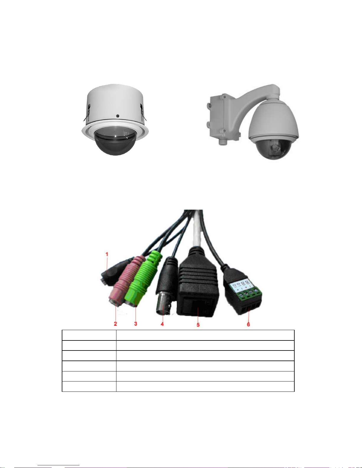
l LOOK
Indoor Housing Outdoor Housing
l
l
l
l
l
l
l
l
l
l Connectors
1 Connect Power Adapter
2 Audio Input
3 Audio Output
4 Video Output
5 RJ-45 Ethernet Connector
6 Digital Input & Digital Output

l OPERATIONAL INSTRUCTIONS
1. Follow the operational instructions for correct use.
2. Please don’t place the product on unstable desk or bracket.
3. Please avoid any liquid permeate inside of the machine in case damage
the product.
4. Before wiring, please follow all electronic safety standards, and using
the original attached power supply adapter.
5. Do not let the camera aim at sun or other lighting objects no matter the
camera is operating or not, otherwise it might damage the CCD camera
permanently.
When the product is out of order, please do not try to fix it by yourself, please
refer to the trouble shooting section of this instruction to figure out the
problems in advance. If the probl em is not found, please contact us or our
authorized dealers directly.

2. SETTING AND INSTALLATION
Note:
l Connect EV6250A to your network by using a standard Cat -5 cable.
l Connect the video output of your camera with video in of video server, using
standard 75O coaxial cable with BNC type connector.
l Connect speaker and active microphone to Audio In / Out.
l Product CD
Product CD in th e package contains:
ü EtroStation™ 3.0 NVR management software
o 16CH Live View / Recording / 4CH Playback
ü EtroStation™ Pro 3.0 NVR management software
o 36CH Live View/Recording/4CH Playback
ü User’s Manual
l Power on IP Camera
Use the power adapter, provided in the package, to power on the IP
camera. The adapter should be connected to 110v~22Ov AC socket.
l Connect to Network
Connect EV6250A and network hub/switch via a standard CAT5 Ethernet
cable and RJ-45 socket. Please pay attention that the PC must be on the
same network domain with the IP camera.
l Connect I/O
Users have to make pin-to-pin correctly to enable this function.
l Enable Audio Function
n The video flicker may occur when enabling or disenabling audio
in and audio out. The situation normally lasts for a second.
l Easy Installation
Step 1: Use the special screw driver to take off the burglar-proof screw.
Prepare the scre ws to mounting on the suitable place.
Caution: Please be sure to follow all the steps of the instructions. Wrong
installation may damage the product.
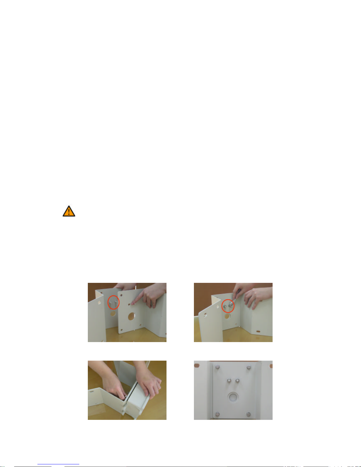
l Bracket installation
- Outdoor 90° Corner Adapter:
1. Combine two brackets, and use the spanner to fix the screw.
2. Turn the screw to tighten the brackets and power box .
3. Complete the assembly
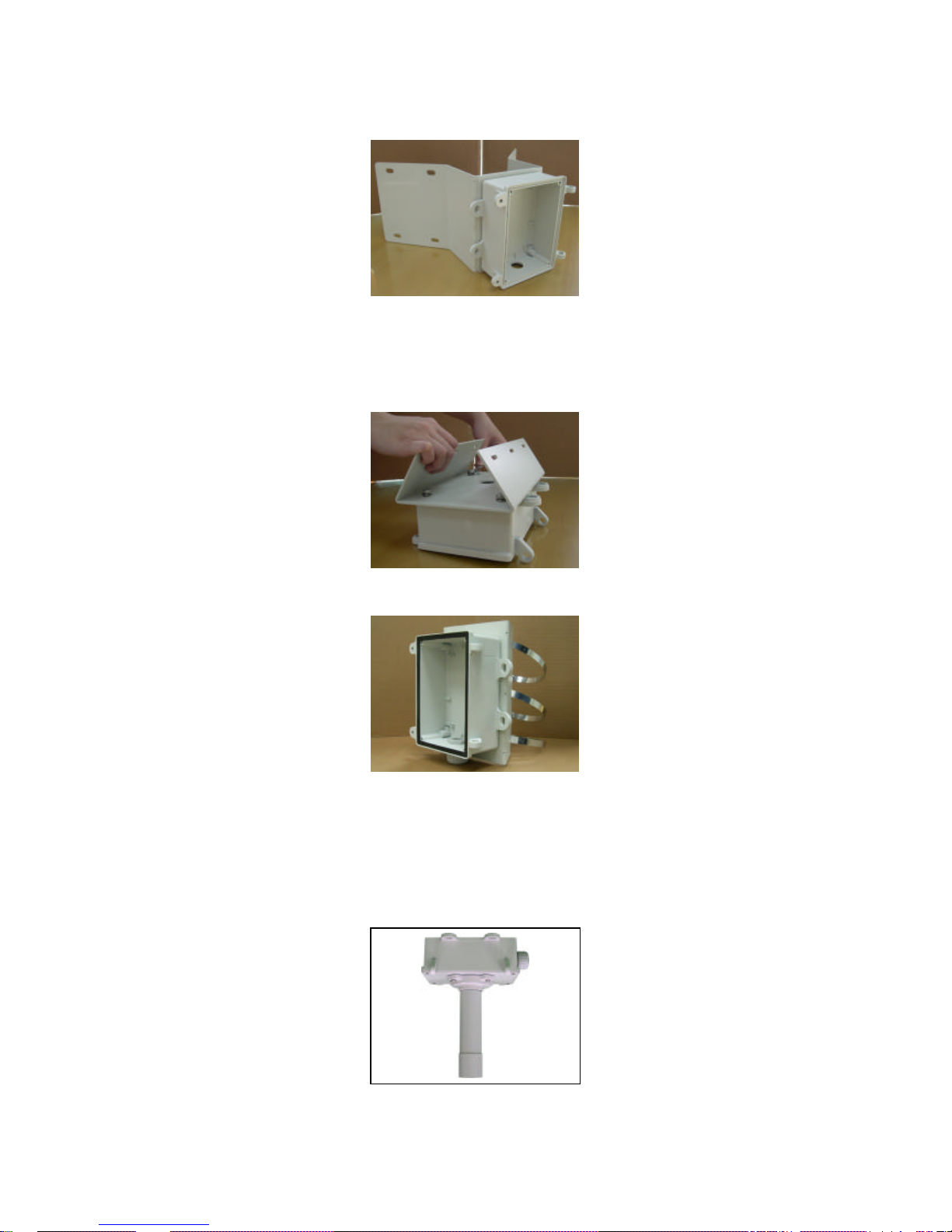
- Pole Mount Bracket:
1. Fixed the bracket on the rear of power box
2. The assembly will be done after the stainless ring is hooped
3. Pendant Mount Bracket:
4. Fixed the iron tube at the above cover of power box
5. Fixed the above cover to the power box namely completes the assembly
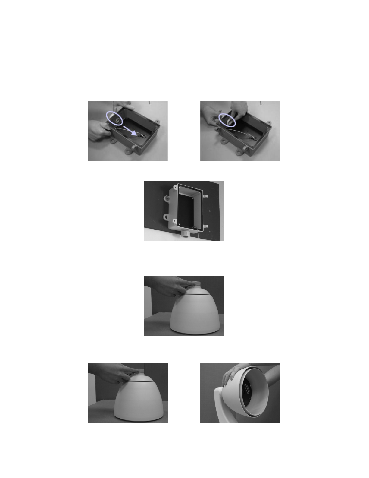
l Outdoor Housing installation
The installed spot must and can hold the product firmly, in case the
image shaken while the camera operates.
1. Put the cable tube into the power box, and screw it
2. Fixing power box on the wall
3. Before assembling housing and bracket, please paste on the
water-repellent tapes. Then revolve the housing from left to right for
fixing
4. Insert comb o cable into bracket to let it pass to housing, then revolve the
housing from left to right for fixing
5. Using hexagon screw driver to fix the housing and bracket
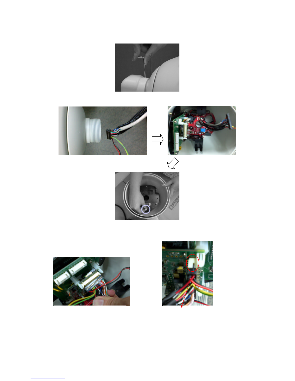
6. Install combo cable, unscrew the bottom screw first
7. Carefully and correctly connect 30-pin main connector, 2-pin video
connector and 2-pin power connector as following pix showed
Proof thinking device 30-pin con nector
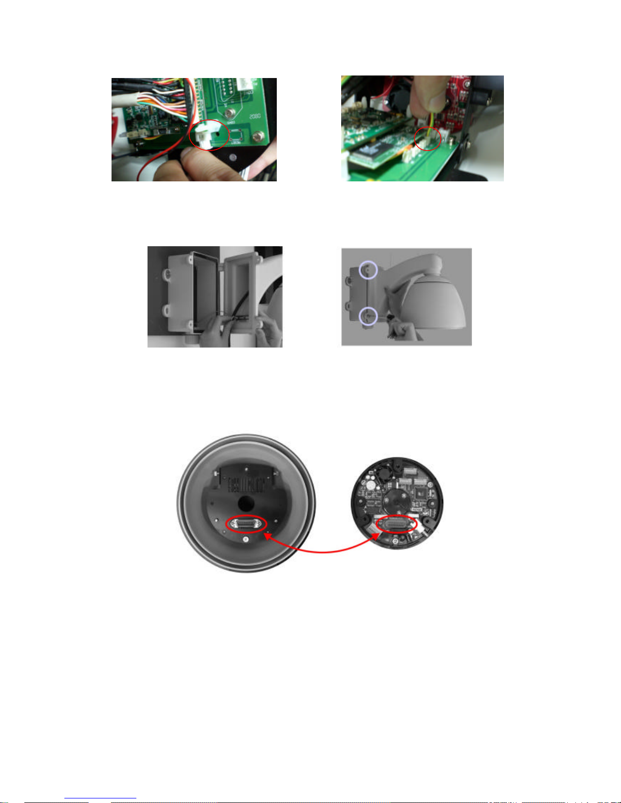
8. Hook up the safety buckle, and screw the two screws to fix the power box
l Camera Installation
1. Aim the camera plug to the bottom socket to connecting
2. You can also follow the triangle in front of camera and aim at the bottom
screw to fixing
Connect video connector with J13 Connect power connector with J12
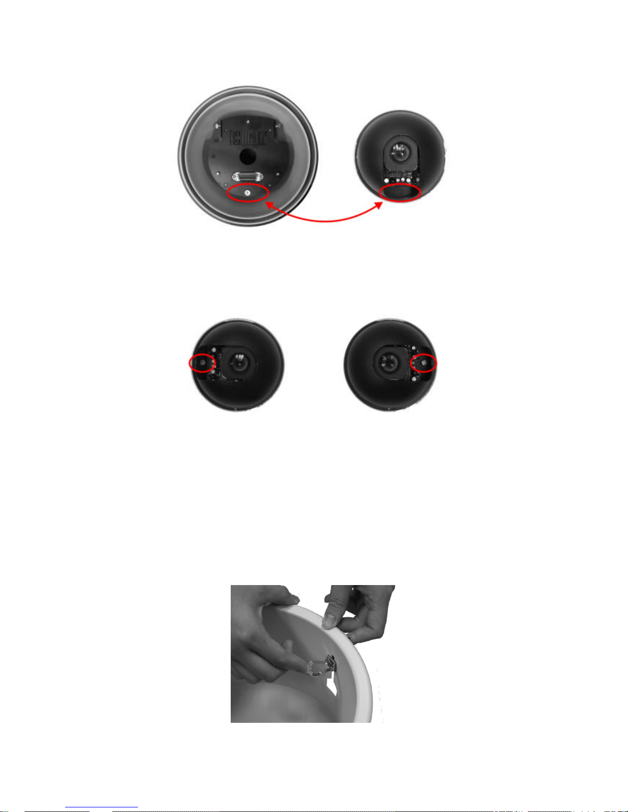
3. After the camera is installed, please turn the camera and fixing the two
side screws.
4. Finally cover up the smoked cover to accomplish the install ation. Please
be sure hands are clean while cover up, or it may dirty the cover. It’s
recommended to tear off the protect membrane after installation is
finished, or wear on gloves
l Indoor Housing installation
1. Outer housing fixing as below, click down the iron slice then pull it up
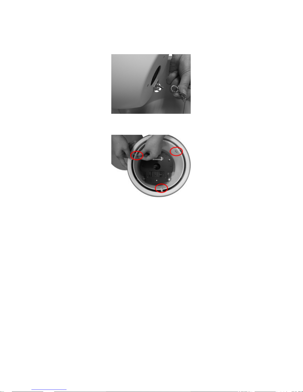
2. Before install inner housing, please hook the safety lock of outer housing
on the fixing socket of inner housing, in case of installation accidents
3. Please fix the three screws on the side before install the camera
4. Combo cable and camera installation same as steps mentioned above in
outdoor part

3. USING EV6250A FOR THE FIRST TIME
l Before You Install Software
ü Please check PC OS platform. Microsoft Windows 2000 or
Windows XP is capable of running EtroStation™ 3.0 software.
ü PLEASE read EtroStation™ 3.0 user’s manual before installation .
l Language Support
ü English
l Install EtroStation™ 3.0
User can easily find the specific IP camera on the network via this
software.
l Browser for Live Viewing and Video Settings
Microsoft IE browser version 6 or higher is recommended. Currently
Mozilla Firefox and others are not compatible.
l Factory Setting – Initial IP Address
Default IP Address: 192.168.1.2
Gateway: 192.168.1.1
Subnet Mask: 255.255.255.0
l Network Domain
Alter the IP address of the PC to the same domain of default value
(192.168.1.2). Users may alter the IP address of the IP camera to the
same of PC via EtroScan™ . Please refer to page 45 to check detailed
information.
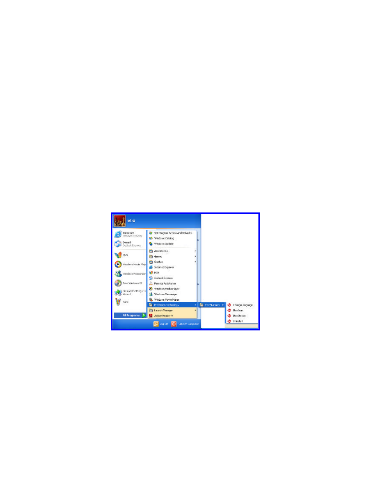
l Use EtroScan™
The software allows users easily and quickl y find the specific IP camera on
the network. Run EtroStation™ 3.0 setup and install the two applications.
The following is the brief instruction:
Select EtroScan™ from the start menu. User can see the following image:
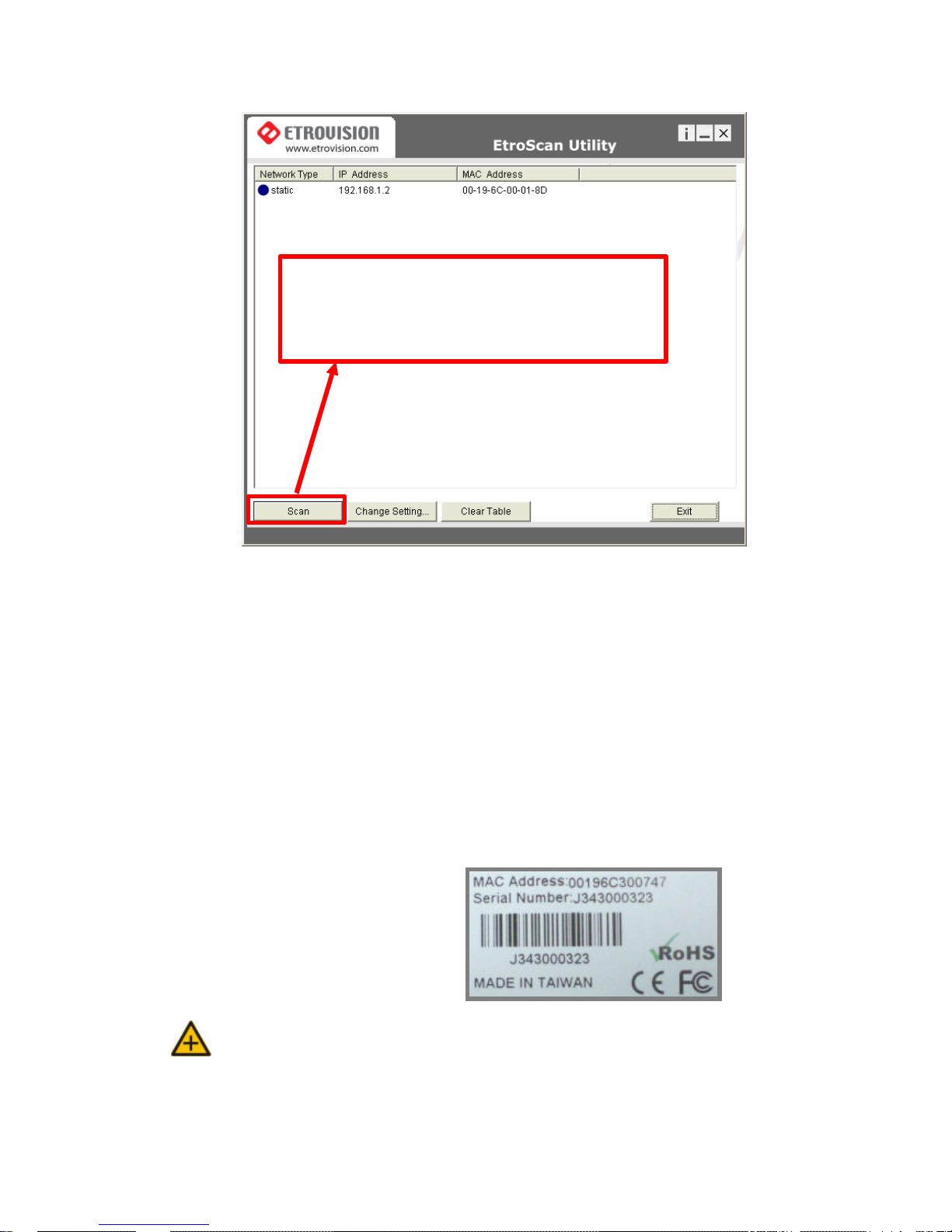
Press Scan button to check the IP and MAC address list. Press Clear
Table button and press Scan again to refresh.
You will find the list of IP and MAC address listed. To indentify your IP
camera you can flip over the IP camera and check the label for MAC
address on the bottom side.
Note: Please pay attention that a completed RMA form must contain the serial
number of the product. For more information, please refer to our
website.
Press Scan to automatically find online Video Server
or
Full Function of Video Server on the network domain
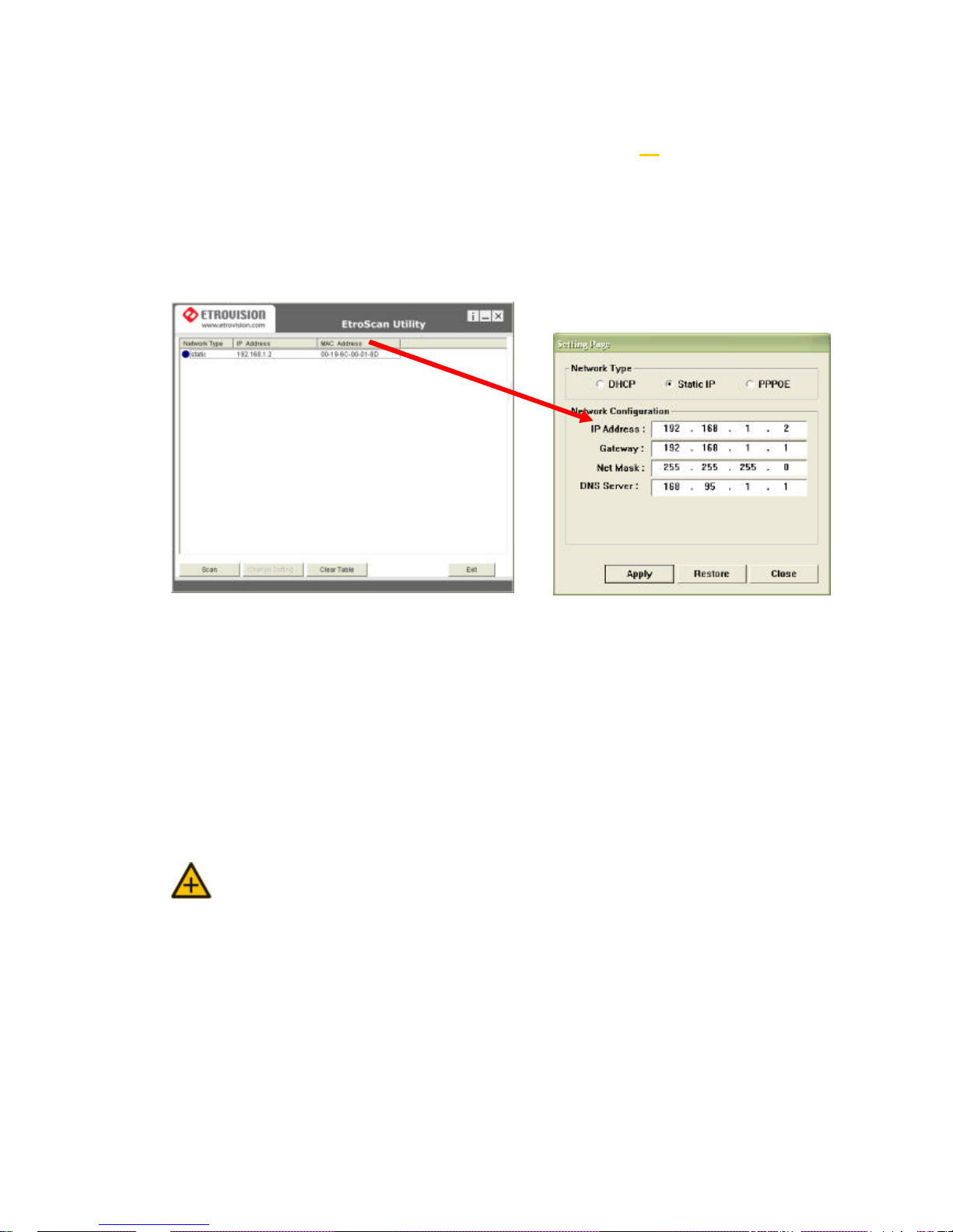
l Change Network Setting via EtroScan™
Double click on a specific IP address; the setting page will pop up. Users
may alter some basic network parameters in this page.
Be sure to press APPLY to enable the new setting
Within 10 seconds, the dialog box would disappear. This indicates that the
new settings are deployed. After typing in the new IP address, user may
close the setting page and wait for 45 seconds. It takes 45 seconds to
restart the system. After rebooting, user may press Scan to check the
new IP address.
Note: “DOUBLE Right Click Function” à Double right click on a specific IP
address on the list; user can quickly open the live viewing browser
page.
Press Exit to quit.
Double click
4. ACCESS IP CAMERA
l Browser
Ø Open an IE browser
Ø Type in the IP address of video server that you found via EtroSacn™ . For
example: 192.168.1.2 (default IP address)
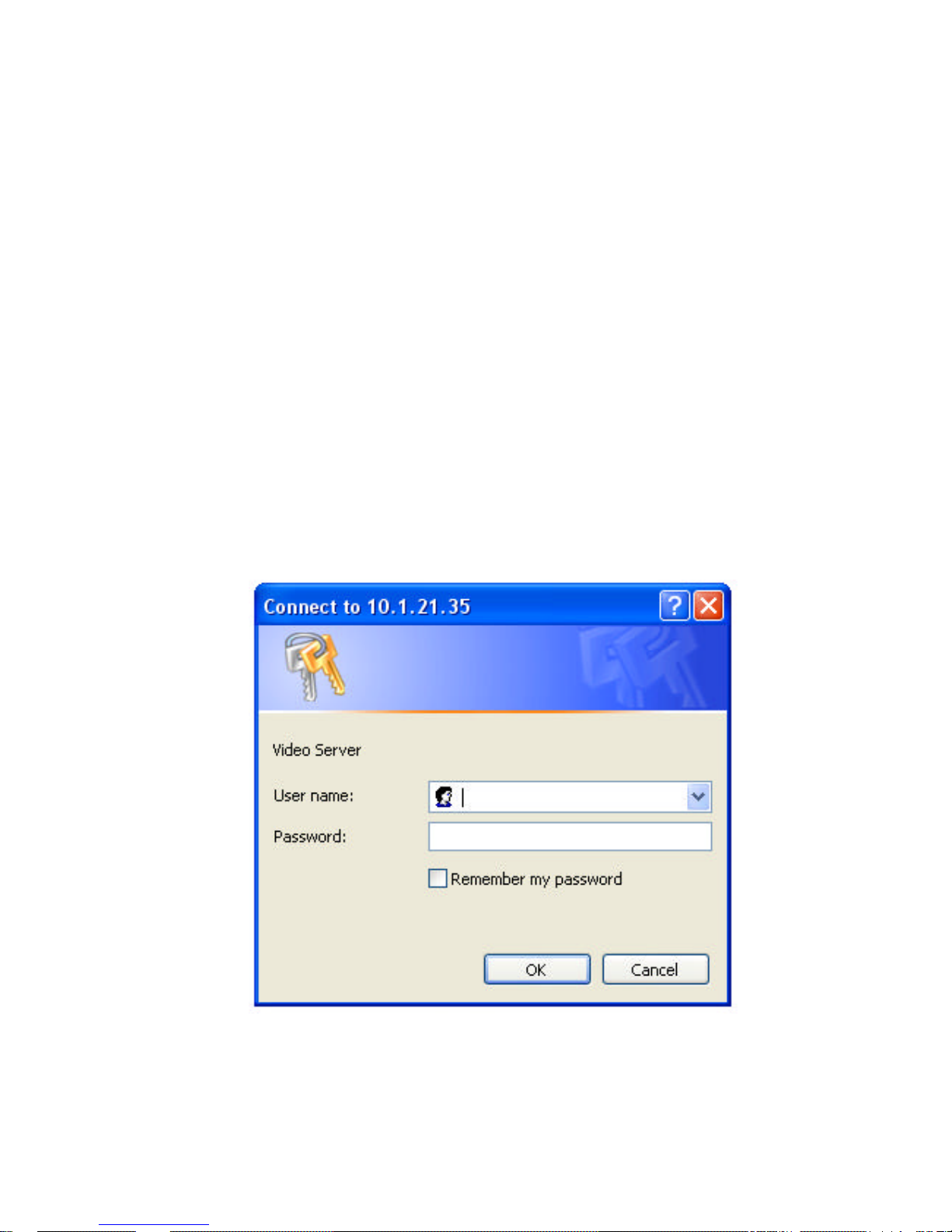
Ø A popup login dialog box will automatically display.
Ø Initial username and password (case-sensitive):
Login: root
Password: pass
Press OK button to access to the live viewing web page.
root
pass
l Initial Username & Password
à Administrator
Ø Default ID / Password = root / pass
Ø The ID of administrator can not be changed or deleted; only the
password is changeable.
Ø Administrator has the authority to view and control system settings.
After logging in with root / pass as administrator, user may see the live
viewing page.
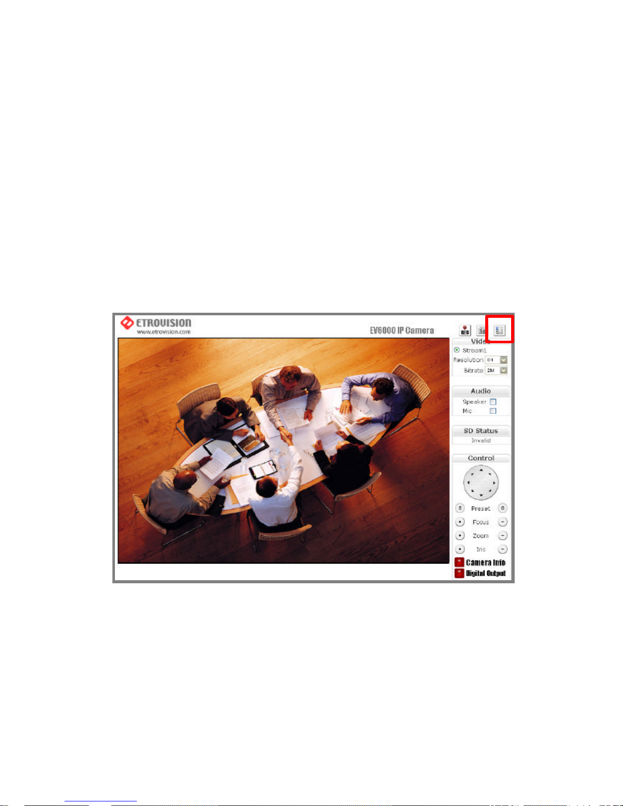
1. There is a toggle button on the top right corner of the live viewing
page.
2. User may press this button to switch from the live viewing page to
the web configuration page and vice versa.
3. Control options are listed on the right side.
4. OSD is displayed on top left corner of the screen .
The sequence is date (mm-dd-yyyy), time, and camera name.
(camera name is optionally displayed)
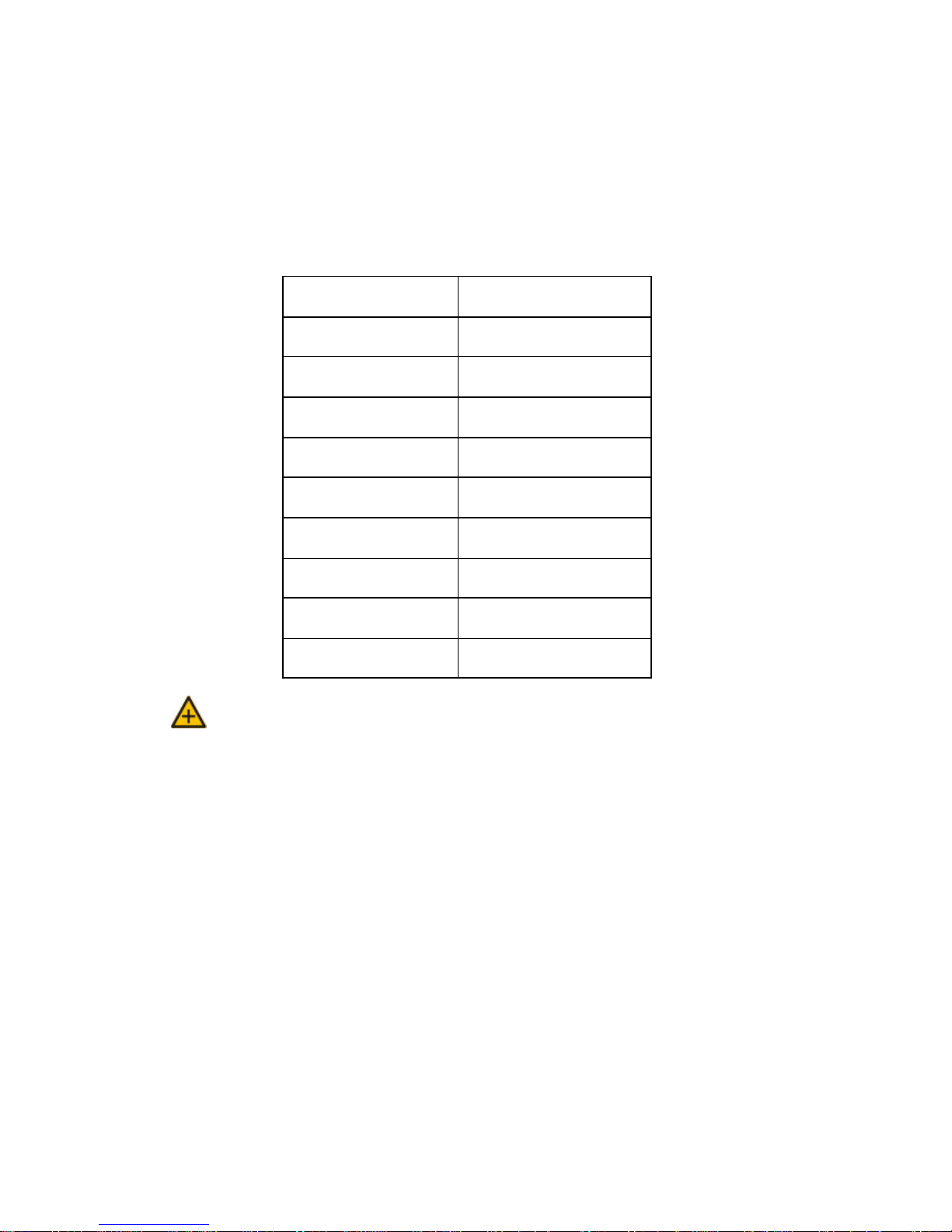
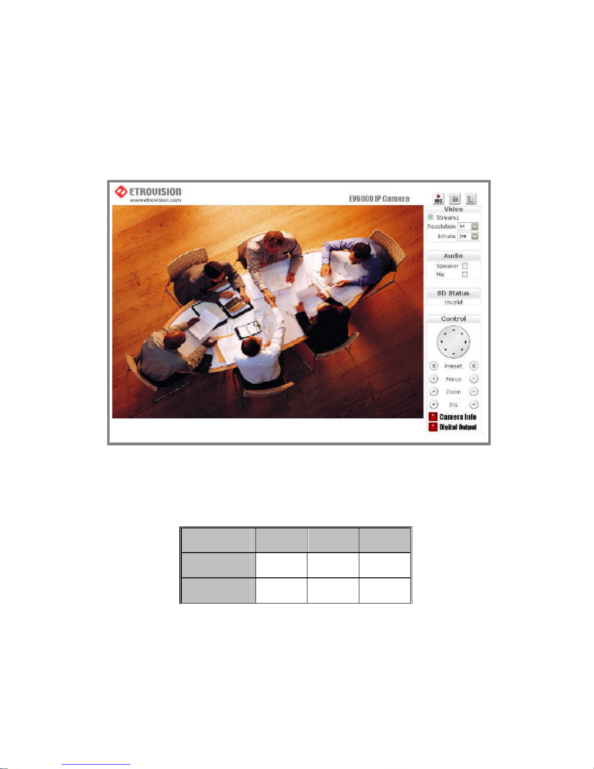
l Control Panel Settings
1. Video / Resolution
The following table shows common resolutions:
2. Video rates / Bit rates
The bit rate values ranges from 64k to 4M and are related with
bandwidth.
Resolution CIF QCIF D1
NTSC
352X240 176X120 720X480
PAL
352X288 176X144 720X576
3. Choose a specific value and the setting will be enable d within few
seconds. The image on the screen might briefly pause.
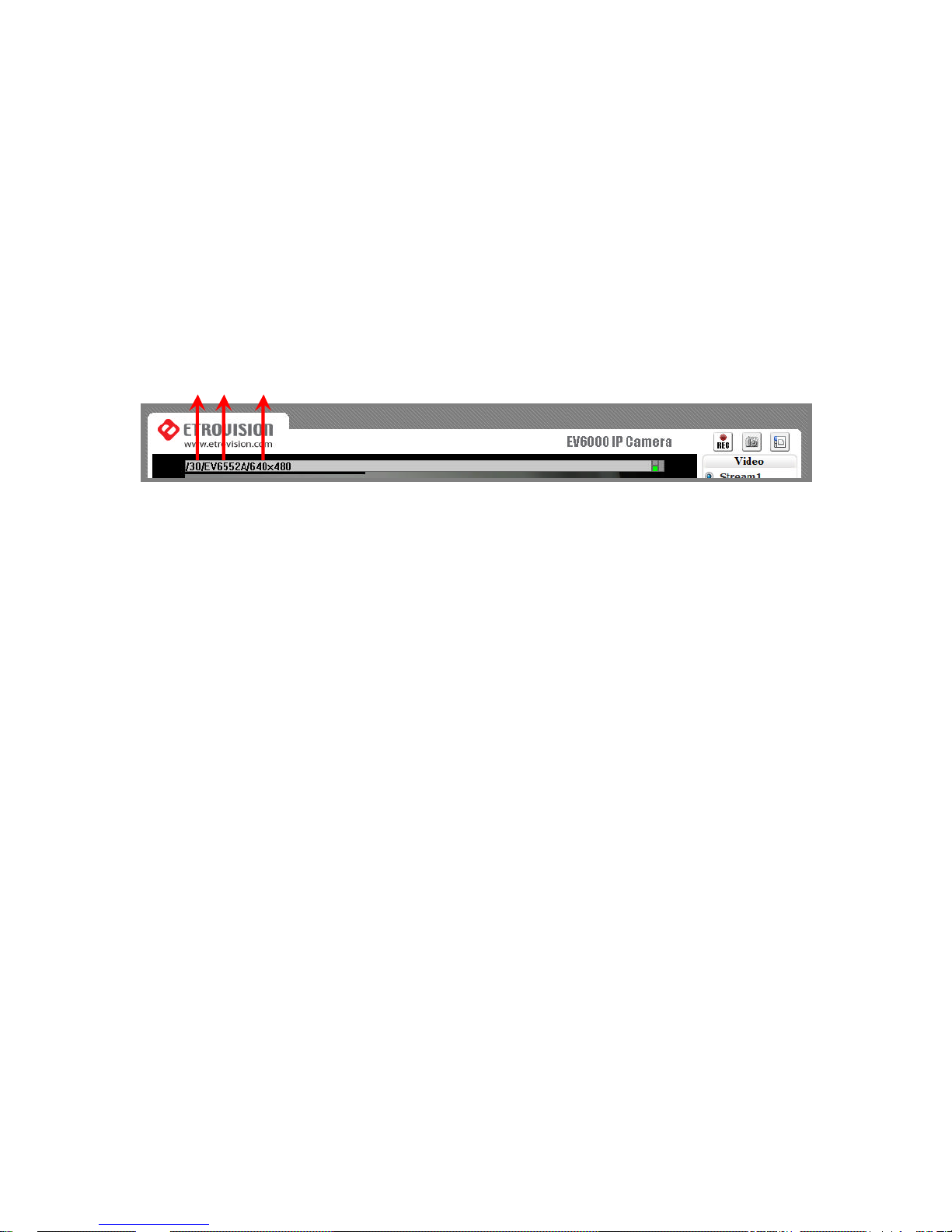
4. Camera information (Please refer to the picture)
The button is on the lower right corner of the living viewing image,
showing video information such as frame rate (fps), model name,
and resolution.
5. Digital Output (Please refer to the picture)
To enable this function, user has to connect the PIN via the Mini DIN
cable. The toggle button works as a switch to enable/disenable
Digital Out function.
FPS Name Resolution
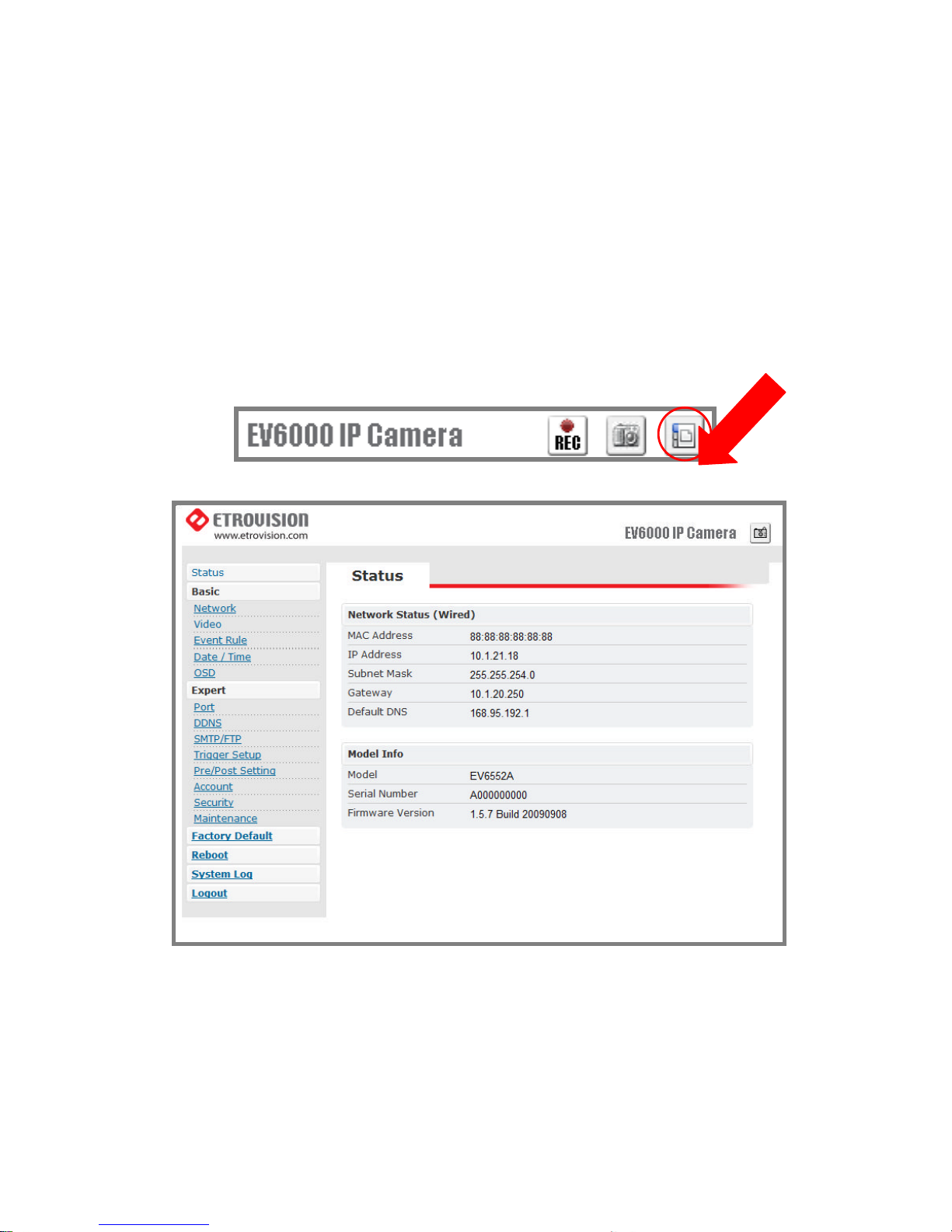
5. WEB INTERFACE SETTINGS – BASIC
EV6250A built-in web interface provides the access to further settings.
Enable the top -right side icon in the live viewing page to access to the
further settings. This button also works as a switch between
configuration and live viewing page. (Please refer to the picture in p.16)
l Status
1. Status is the first item of the setting options.
2. This page shows the IP address, MAC address of the video server,
hardware, firmware information , and other related information.
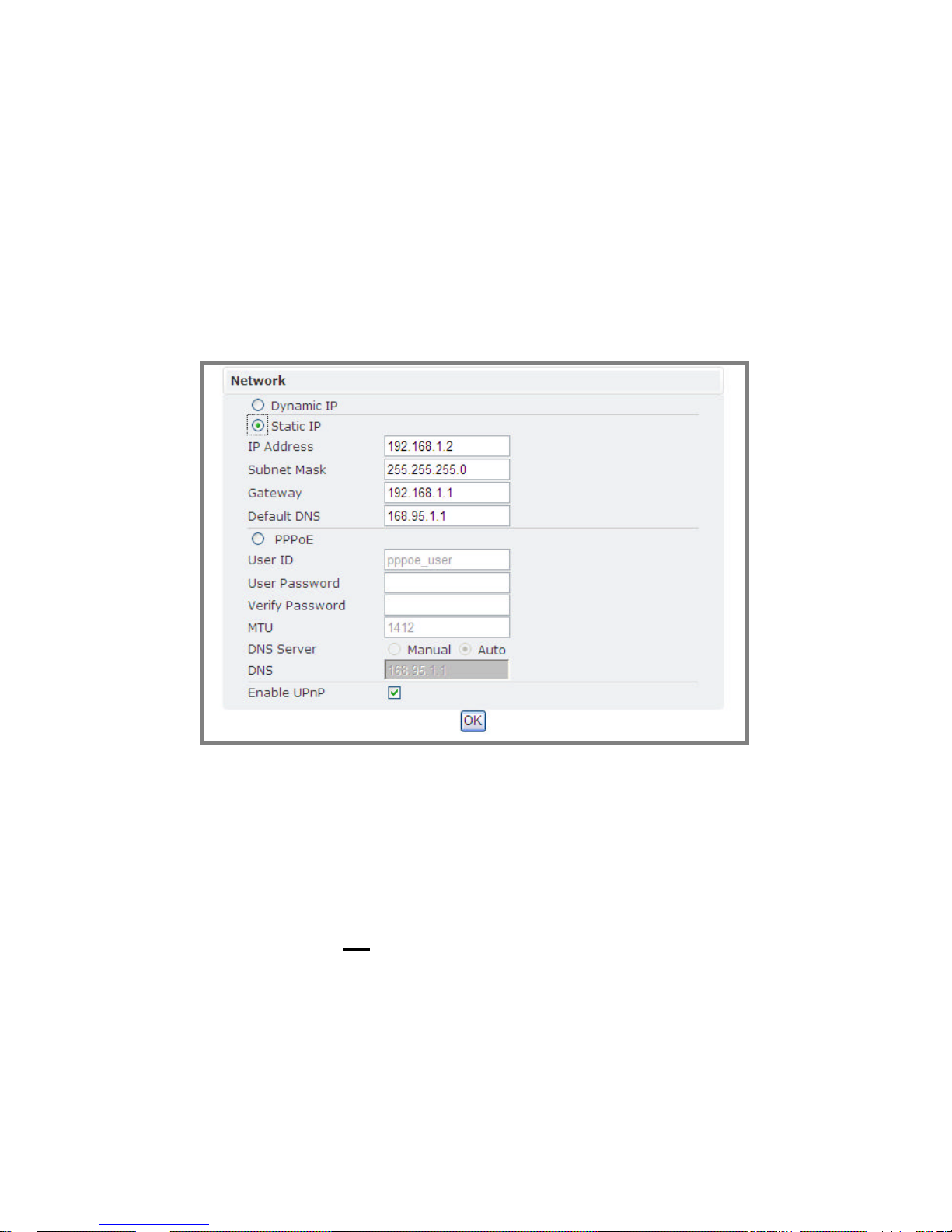
l Network
There are three types of network connection: STATIC, DYNAMIC and,
PPPoE.
à Static IP
1. IP Address
Please confirm with the network administrator.
2. Subnet Mask / Gateway / Default DNS
Please confirm with the network administrator.
3. Be sure to press “OK” to save the new setting.
4. Reboot will be required and automatically triggered after pressing OK.
Please wait for a moment to the count down timer stop. The page will be
redirected to the initial login one.
 Loading...