

EtroVISION EV6150A, EV6151A, EV6156A, EV6153A, EV6551A User Manual
...
IP Camera & Video Server
User’s Manual
Firmware Version 1.9.5
Document Version 1.4

About This Guide
The User’s Manual provides functionality and instructions for Etrovision’s IP
cameras and video servers employing firmware version 1.9.5.
Before Using the IP Camera/Video Server
Check the PC requirements
Review the OS platform requirements
Read an special and import precautionary information
Having basic knowledge of network setup and configuration will be helpful
Important Announcements
NOTE: This icon represents a tip for operation.
CAUTION: This icon stands for an action that could affect an operation or mildly
impair the system.
WARNING: This icon indicates an action that will likely impair the system.
Disclaimer
© 2007 Etrovision Technology. All rights reserved.
EtroLink™ & AnyUSB™ are trademarks of Etrovision Technology; other product or
service names mentioned herein are the trademarks of their respective owners.
Information contained in this document may be superseded by updates. No
representation or warranty is given and no liability is assumed by Etrovision
Technology with respect to the accuracy or use of the information, or infringement of
patents or other intellectual property rights. No licenses are conveyed, implicitly or
otherwise, under any intellectual property rights.

1 INTRODUCTION ...............................................................................1
1.1 Camera Model Differences.......................................................................... 1
2 THE LIVE VIEW.................................................................................2
2.1 OSD (On-Screen Display)........................................................................... 2
2.2 Setup, Snapshot and Record Video............................................................3
2.3 Video........................................................................................................... 3
2.4 Audio........................................................................................................... 3
2.5 SD Status.................................................................................................... 3
2.6 Control (PTZ Controls)................................................................................ 4
EV6250A Speed Dome...............................................................................5
2.7 Camera Info and Digital Output...................................................................5
Camera Info ................................................................................................ 5
Digital Output .............................................................................................. 6
3 THE SETTINGS PAGE – BASIC.......................................................7
3.1 Status.......................................................................................................... 9
3.2 Network....................................................................................................... 9
Static IP.......................................................................................................9
Dynamic IP Address .................................................................................. 10
PPPoE Settings......................................................................................... 11
UPnP.........................................................................................................11
3.3 Video......................................................................................................... 12
Stream 1....................................................................................................12
Video Setting.............................................................................................12
Max Client................................................................................................. 13
Stream 2....................................................................................................14
Color Setting ............................................................................................. 14
3.4 Audio......................................................................................................... 16
3.5 Event Rule................................................................................................. 17
Events Handled......................................................................................... 17
Actions Triggered......................................................................................17
Events and Actions....................................................................................18
Activating Events....................................................................................... 20
Modifying Activated Event Rules...............................................................20
Deleting Events.........................................................................................21
3.6 Date & Time .............................................................................................. 21
Client PC Time..........................................................................................21
Time Server............................................................................................... 22

3.7 OSD (On-Screen Display)......................................................................... 22
4 THE SETTINGS PAGE – EXPERT .................................................24
4.1 PTZ Control (Pan, Tilt, Zoom)................................................................... 24
4.2 Port............................................................................................................25
4.3 DDNS (Dynamic DNS).............................................................................. 25
4.4 SMTP/FTP ................................................................................................ 26
Remote SMTP Setup ................................................................................27
Remote FTP Setup....................................................................................28
4.5 Trigger Setup.............................................................................................28
Digital Input............................................................................................... 29
Periodic Timer...........................................................................................29
Motion Detection .......................................................................................29
Video Loss ................................................................................................ 31
4.6 Pre/Post Setting ........................................................................................32
4.7 SD Card .................................................................................................... 32
4.8 NAS Setting (Network Attached Storage).................................................. 33
4.9 Account..................................................................................................... 34
The Administrator Account........................................................................ 35
User Accounts...........................................................................................36
Guest Permission...................................................................................... 36
4.10 Security..................................................................................................... 37
Network Security.......................................................................................38
Power LED................................................................................................41
4.11 Maintenance.............................................................................................. 41
Language.................................................................................................. 42
Firmware Update....................................................................................... 42
System Configuration (Backup / Restore)................................................. 44
Factory Default..........................................................................................45
5 REBOOT..........................................................................................46
6 SYSTEM LOG..................................................................................47
7 LOGOUT..........................................................................................48
8 WIRELESS CONNECTIVITY...........................................................49
8.1 Web Interface Configuration...................................................................... 49
8.2 EtroLink™ USB Configuration Port ...........................................................53
9 EV6156A COLOR SETTINGS.........................................................57
9.1 Menu Options............................................................................................59
IRIS........................................................................................................... 59
AGC/SENS................................................................................................ 59

BACKLIGHT..............................................................................................59
WHITE BALANCE..................................................................................... 60
GAMMA/ENHANCE.................................................................................. 60
IR-SET ...................................................................................................... 60
DIGITAL ZOOM ........................................................................................ 60
H/V REVERSE..........................................................................................60
MOTION DETECT.....................................................................................61
LANGUAGE.............................................................................................. 61
MASK........................................................................................................ 61
OSD ..........................................................................................................61
CROSS LINE/FREEZE .............................................................................62
POSI/NEGA .............................................................................................. 62
DIGITAL OUT............................................................................................ 62
TITLE ........................................................................................................62
PRIORITY................................................................................................. 62
PRESET/PHASE....................................................................................... 63
10 ADDITIONAL INFORMATION .........................................................64
11 GLOSSARY.....................................................................................65

1
1 INTRODUCTION
This document covers functionality and usage of the web interface for IP cameras
and video servers with firmware version 1.9.5. Specific model information can be
found in the model specification which can be found in the Installation Guide for the
corresponding model.
For the sake of convenience, “IP camera” and “camera” will be used to reference
both IP cameras and video servers. “Video server” will be used where there is a need
for clarity.
1.1 Camera Model Differences
Although most of the operations and functions being the same amongst models,
there are some differences. Differences are highlighted where applicable.
The following table highlights primary functionality that differs between models.
These differences will determine if certain items and settings will exist in the Live
View and/or Settings page.
SD
Card
PTZ
Capable
WiFi
Color
OSD
EtroLink
Box
EV6150A x x x x
EV6151A x x x x
EV6153A x x x x
EV6156A x x x x x
Dome
EV6551A x
EV6552A x
EV6552R
Megapixel
EV8150A x x x x
Outdoor
EV6353A x
EV6355A x
EV6356A x
Speed Dome
EV6250A x x
Video Server
EV3151 x x
EV3151A x x x
For example, if a camera isn’t PTZ capable (e.g. EV6552A), then the PTZ controls will
not be present in the Live View page and the PTZ settings option will not be present
in the Settings page.
2
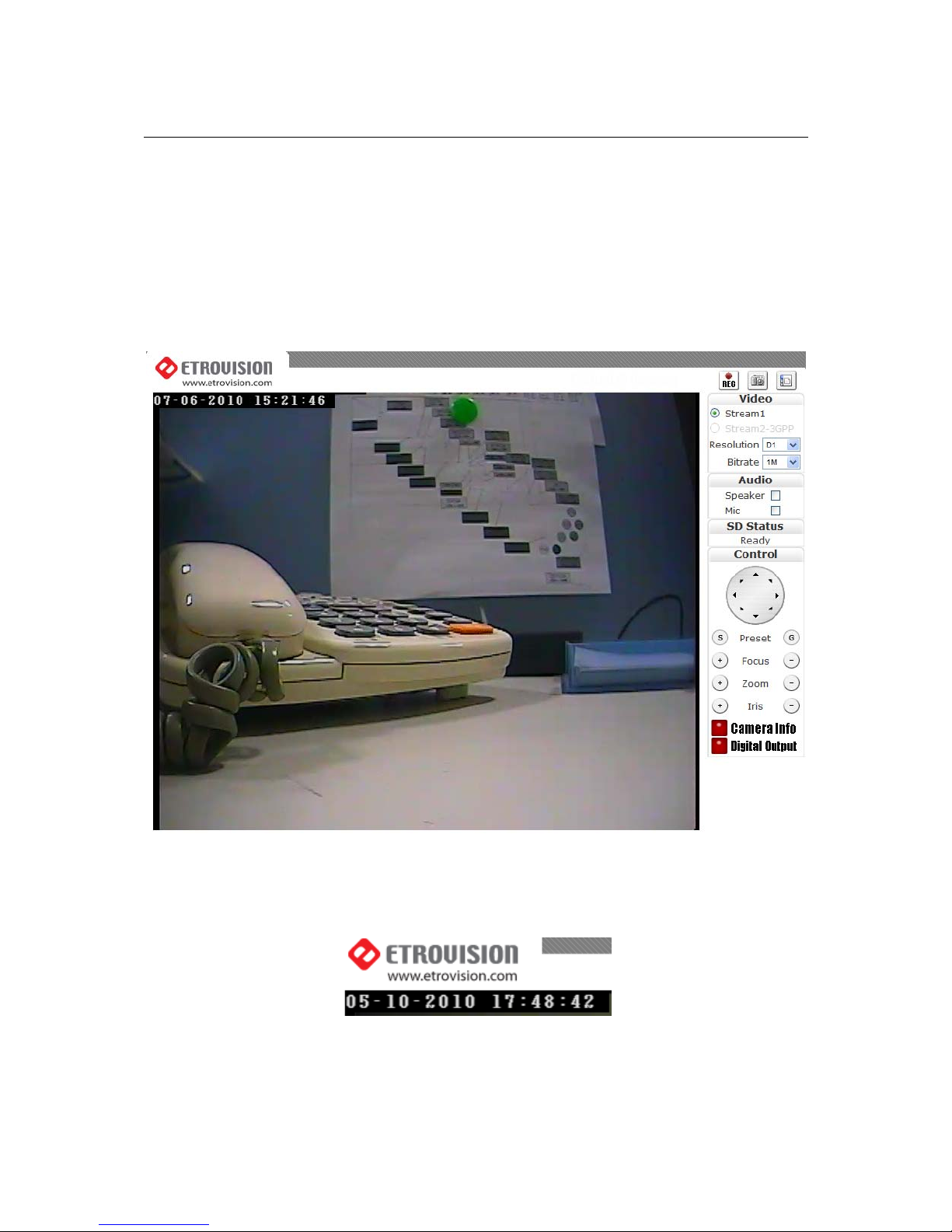
2 THE LIVE VIEW
The IP camera web interface is made up of two main pages: the Live View page and
the Settings page. The Live View provides the current display from the IP camera
along with selected settings, configuration and functionality.
After logging into the IP camera via the browser, the user is first presented with the
Live View page.
Below is an example of the Live View page. Following the screenshot is a discussion
of the different areas within the Live View page.
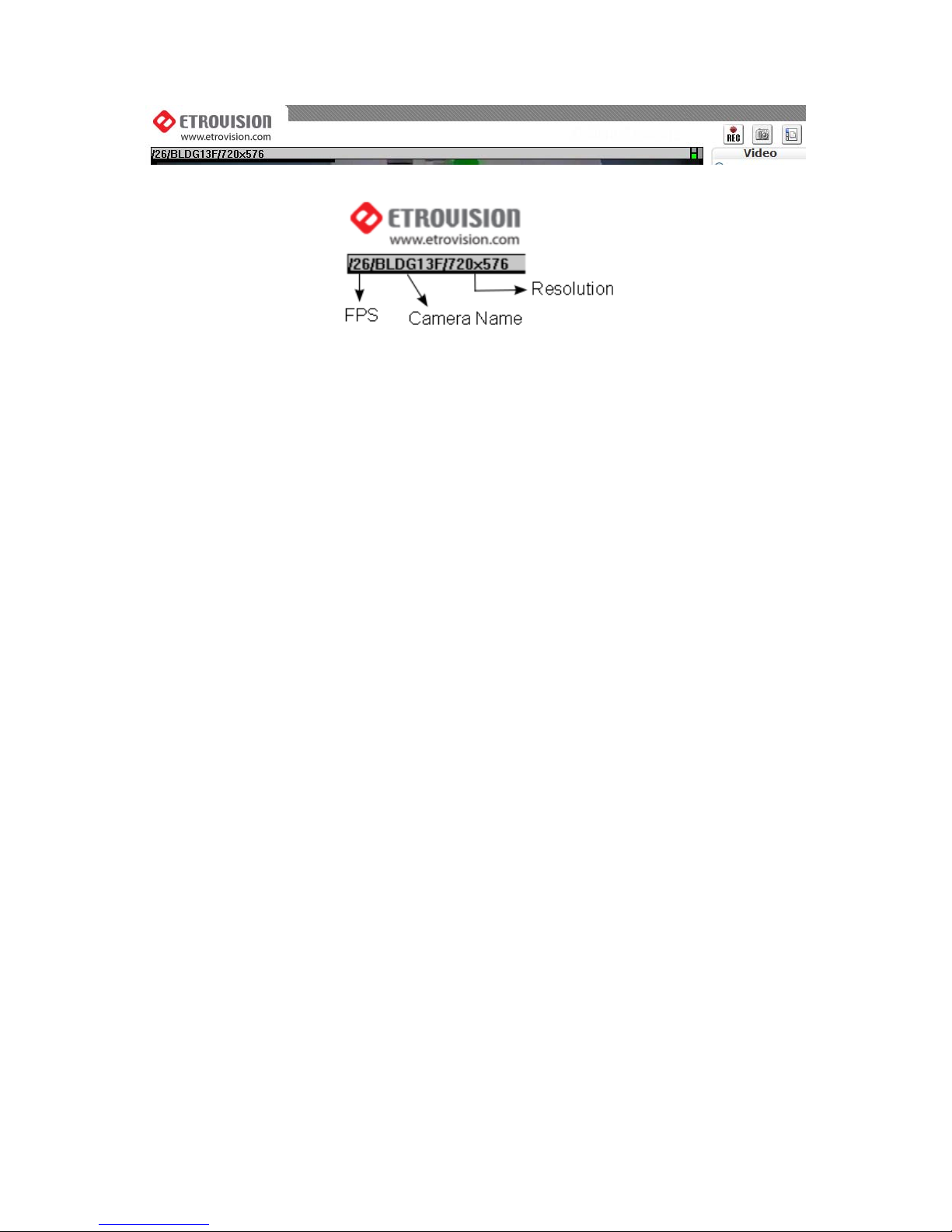
2.1 OSD (On-Screen Display)
In the top left corner is the OSD (On-Screen Display).
By default, the date and time are displayed in the format MM-DD-YYYY
HH24:MI:SS; the camera name can also be displayed (see “OSD” section for
information on altering the OSD settings).
3
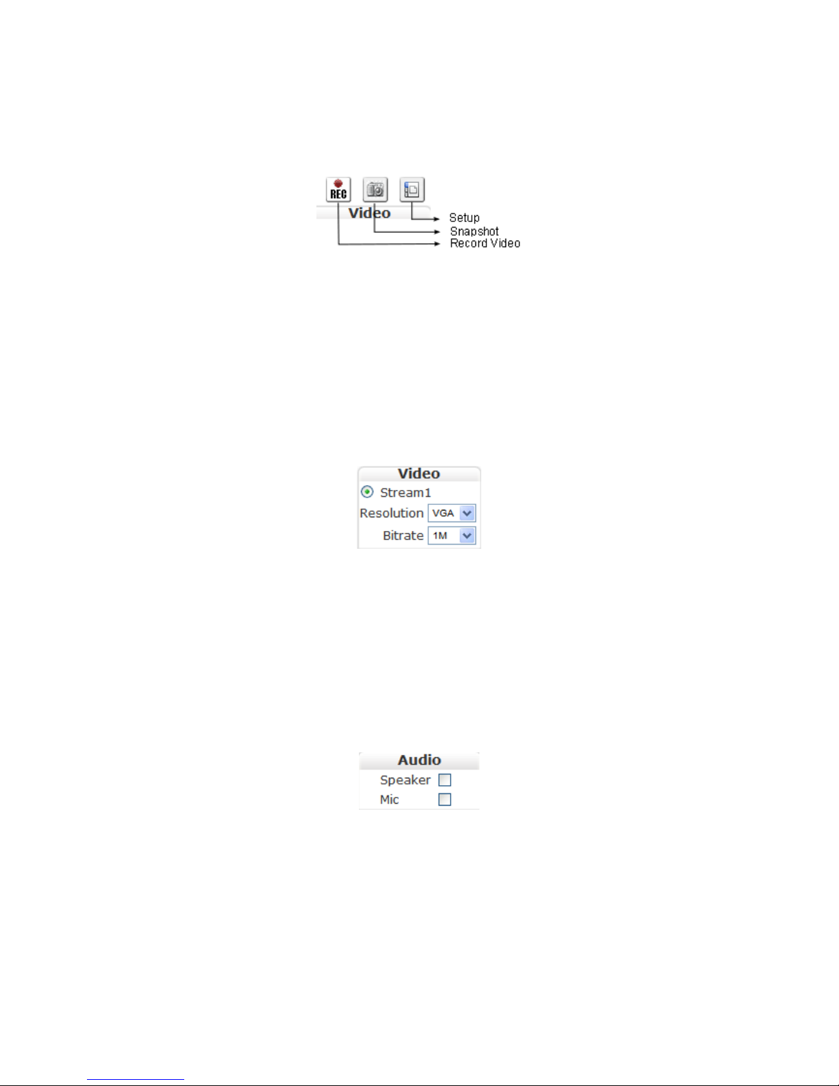
2.2 Setup, Snapshot and Record Video
In the top right corner of the screen are three controls.
“Setup” switches from the Live View page to the administration configuration
page where most of the IP camera configuration is performed.
“Snapshot” can be used to take snapshot pictures. The files are stored locally
on the PC.
“Record Video” starts and stops recording of video. The files are stored
locally on the PC.
2.3 Video
Below the Setup/Snapshot/Record controls are the video and resolution controls.
“Stream2” will also be displayed if it has been enabled (see the Settings Page
“Video” section for more information).
The resolution and bitrate can be modified here. In the drop down box, choose
one of the options.
Changes take place a few seconds after modification; the image on the screen
might briefly pause while changes are implemented.
2.4 Audio
The “Audio” check boxes enable/disable speaker and microphone (Mic)
capabilities. The appropriate cables need to be connected into the back of the
camera. (See the “Audio” section for more information).
2.5 SD Status
Note: Dome, Outdoor and Speed Dome models do not have SD Card
functionality as of this firmware version.
4
The “SD Status” is the secure digital (SD) card status. If no card is present then
the status will be “Invalid”. See the “SD Card” section for more information.
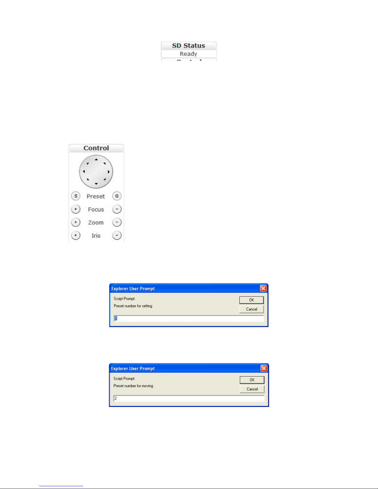
2.6 Control (PTZ Controls)
Note: Dome and Outdoor models do not have PTZ functionality as of this
firmware version.
The Control section allows operating the PTZ controls from the Live View.
The round dial with directional arrows controls the
directional movement of the camera.
“Preset” is used for configuring and using camera directional
presets. There are two buttons: S and G.
Focus, zoom and iris controls are modified using the + and –
buttons.
S is used to set a specific location view. First position the camera to view a
specific area. Next click S which displays a window prompting the ID to assign
the specific preset.
Enter an alphanumeric ID for a specific preset and click OK.
G is used to move the camera to a specific preset. Click G, enter the desired
preset ID and click OK.
5
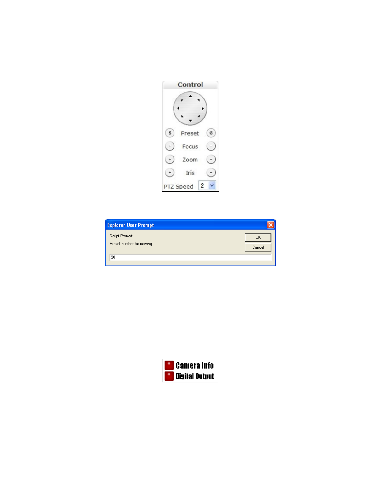
EV6250A Speed Dome
The EV6250A has some slight differences. Below are the PTZ controls in the
EV6250A.
The “PTZ Speed” controls how fast PTZ movement occurs. Values range from 1-6.
The EV6250A has a preconfigured PTZ setting number, 98.
This setting will result in the camera continuously panning 360° on the current
axis.
2.7 Camera Info and Digital Output
Camera Info
The 2 buttons on the bottom right are “Camera Info” and “Digital Output”.
The “Camera Info” button displays video information such as frame rate (fps),
model name, and resolution. This information is displayed where the OSD
information is normally displayed, the top left corner.
Below are two screenshots displaying when the “Camera Info” button is enabled.
Note that the OSD information is no longer viewable when the button is enabled.
6
Digital Output
The “Digital Output” control is a toggle button that sends a Digital Out signal.
This functionality is available if a corresponding device is connected to the IP
camera using the digital I/O terminal.
7
3 THE SETTINGS P AGE – BASIC
The web interface is made up of two main pages: the Live View page and the
Settings page. The Live View page interface was introduced in the previous section.
The Settings page is primarily used for viewing and configuring the IP camera’s
settings.
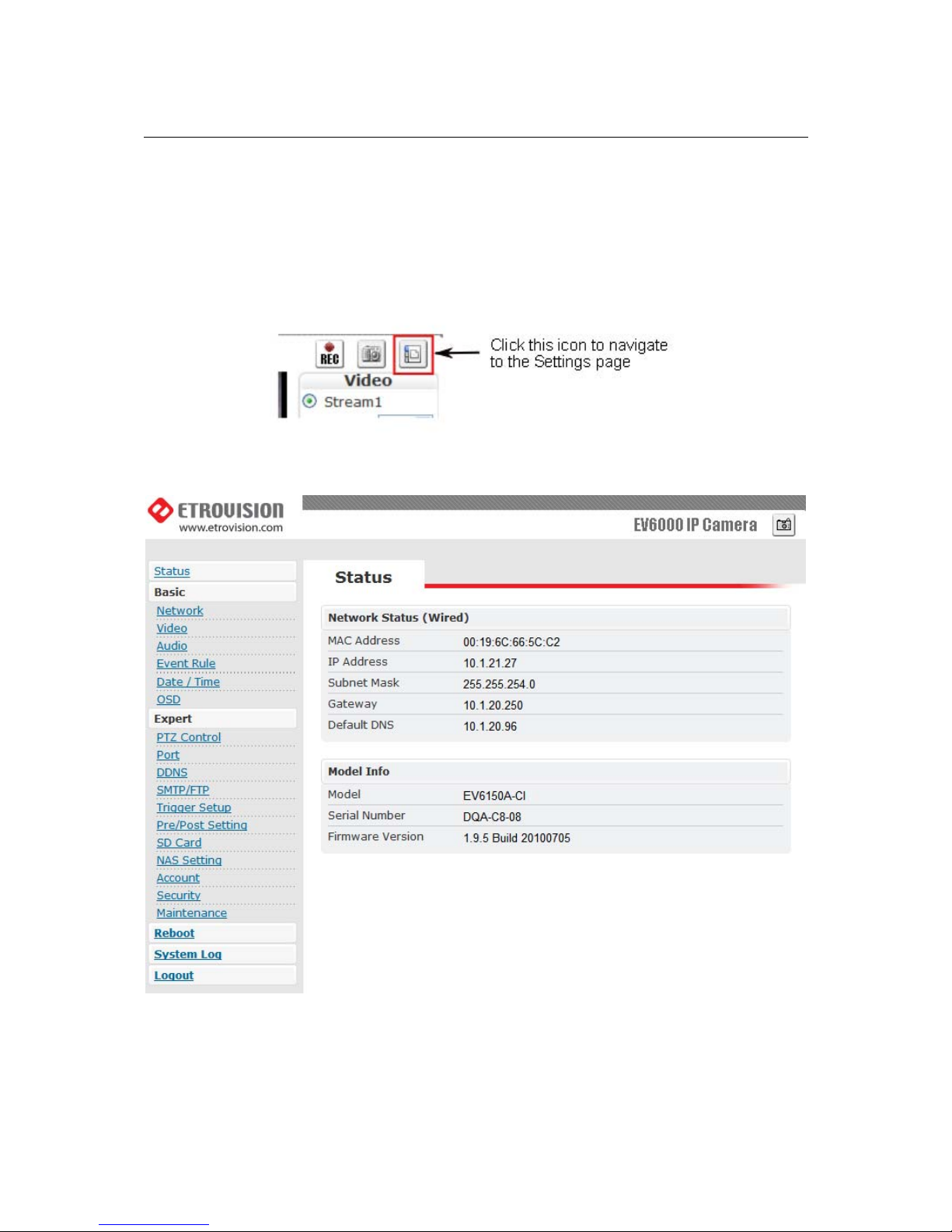
From the Live View page, click the Settings page icon at the top right side:
Below is a screenshot of the Settings page interface. The initial page displayed is the
“Status” page.
The left side of the page lists the different setting sections which can be viewed and
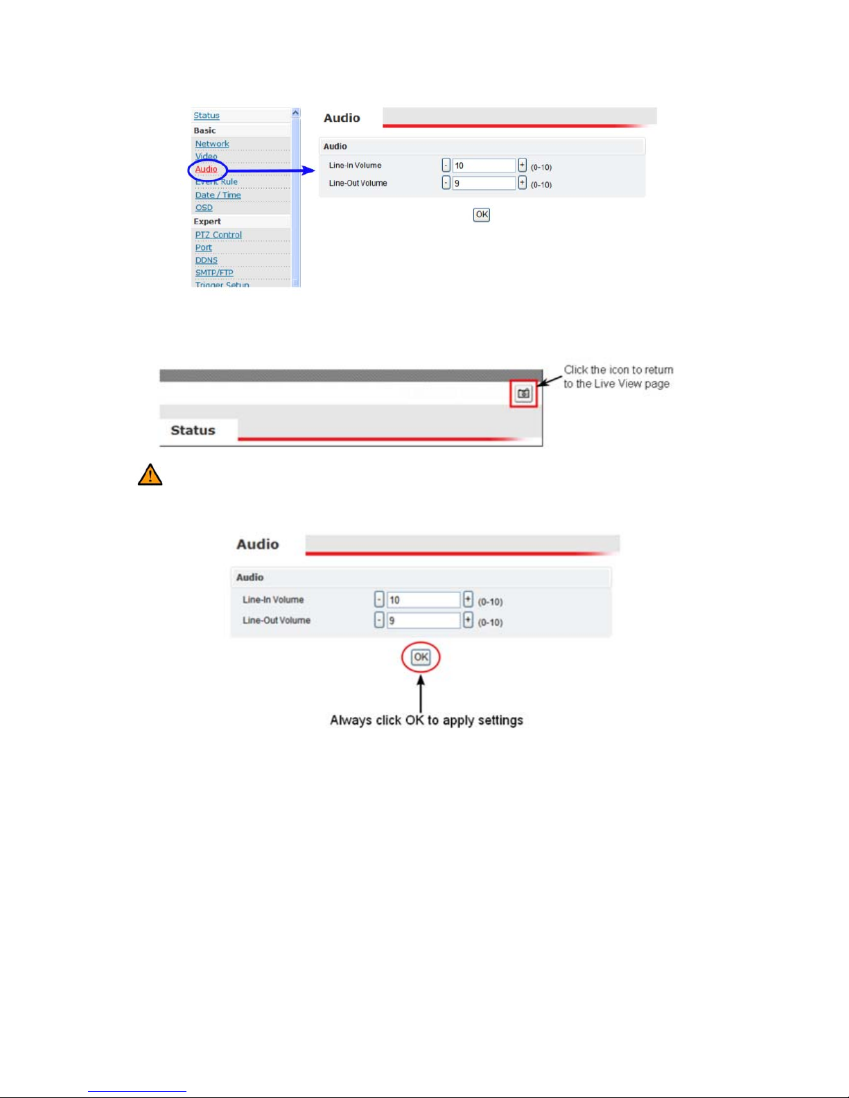
modified. For example, clicking “Audio” will display the “Audio” configuration
settings in the right pane.
8
From the Settings page, click the Live View page icon (highlighted in red in the
upper right corner) to return to the Live View page.
Configuration changes in the Settings page require clicking the OK button.
Otherwise, changes will not be applied.
The following discusses the different basic configuration options within the Settings
page.
9
3.1 Status
The Status page is always the initial page displayed when switching to the
configuration view. Various basic information related to the IP camera is
displayed here.
The page only displays information; no changes can be made here.
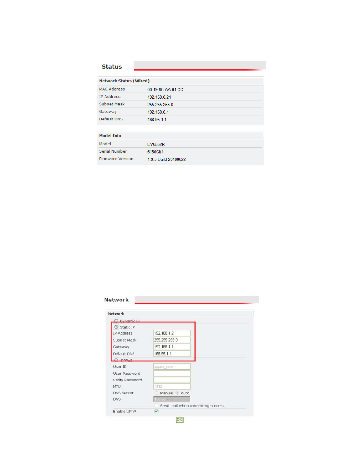
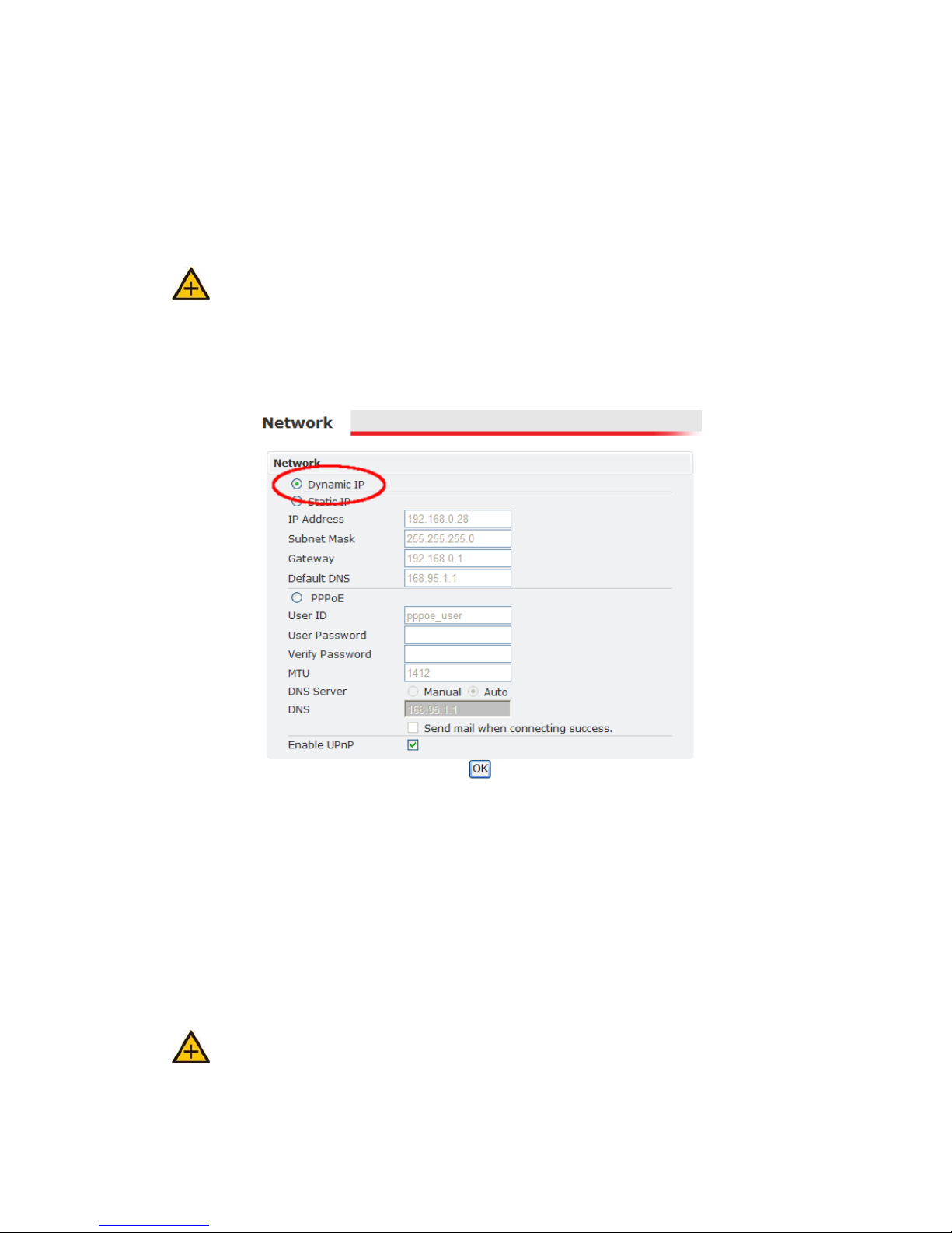
3.2 Network
There are three available types of wired network connections available: STATIC,
DYNAMIC and, PPPoE.
Please confirm all network related settings with the network administrator prior
to making any changes.
Static IP
10
1. Enter the IP Address.
2. Enter the Subnet Mask/Gateway/Default DNS
3. Be sure to press OK to save the new setting.
4. A window prompting a reboot will be displayed. Click OK to proceed with
the reboot (or Cancel if you wish to return to the Network settings).
5. A timer will countdown the approximate time for reboot to complete. The
page will be redirected to the live view page using the new IP address.
Use EtroScan™ to find the MAC addresses after reboot and ensure the IP
address is correct. If the IP was changed in web configuration, you must access
the initial login page using the new IP after the reboot.
Dynamic IP Address
1. Select DHCP
2. Press OK button
3. Reboot will be required and automatically triggered after pressing OK.
4. A window prompting a reboot will be displayed. Click OK to proceed with
reboot (or Cancel if you wish to return to the Network settings). A timer will
countdown the approximate time for reboot to complete.
The browser will likely not reload since the IP is uncertain. The new IP address
will likely need to be determined using EtroScan™ and the IP camera’s MAC
address. After determining the new IP address, use this IP address to access the
web interface.
Always use EtroScan™ to find the MAC addresses after reboot and double
check the IP address. Make sure the IP address is correct. If IP was changed in
web configuration, you cannot return to initial login page after reboot.

11
PPPoE Settings
If the network supports PPPoE like xDSL, then PPPoE can also be used for
connectivity.
1. Select PPPoE
2. Enter the PPPoE ID and password.
3. Enter the MTU (Maximum transmission unit)
4. The DNS server can be manually set or “Auto” can be used to automatically
detect the DNS IP address.
If xDSL does not use static IP addresses, then DHCP should be used.
UPnP
To enable UPnP (Universal Plug and Play)connectivity, check the “Enable UPnP”
box. This will allow accessing the camera via UPnP connectivity from a computer.
12
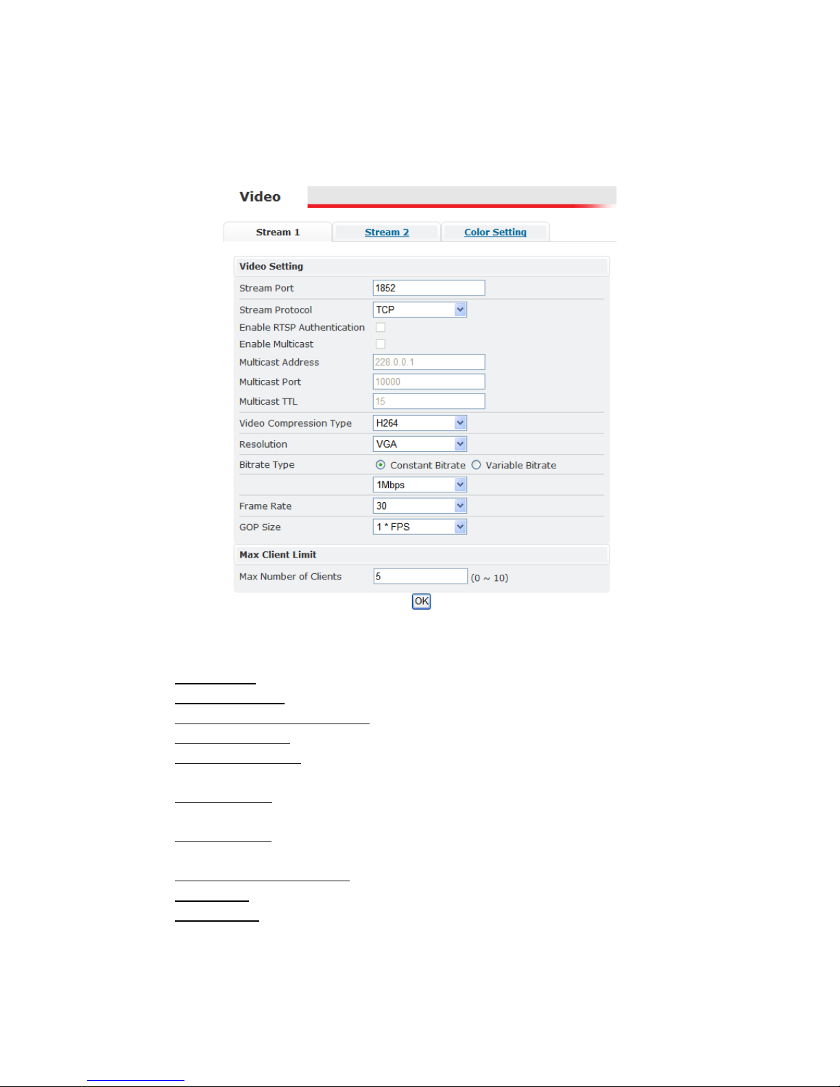
3.3 Video
Stream 1
Video Setting
Stream Port: Stream 1 port value setting; 1852 is the default.
Stream Protocol
: TCP and UDP(RTP)
Enable RTSP Authentication
: option available if UDP(RTP) protocol selected
Enable Multicast
: option available if UDP(RTP) protocol selected
Multicast Address
: option available if multicasting enabled; the default value
is 228.0.0.1. Verify address with the network administrator before applying
Multicast Port: option available if multicasting enabled; the default value is
10000. Verify address with the network administrator before applying
Multicast TTL: TTL (Time To Live); option available if multicasting enabled;
the default value is 15
Video Compression Type: H264, MJEPG, MPEG-4
Resolution
: this setting can also be set from the live view page
Bitrate Type
: constant bit rates and variable bit rates. The Bitrate option is not
present when using MJPEG video compression
Constant values range 64Kbps to 4Mbps; 2Mbps is the default.
13
Variable values range from 15 to 51; this value is relative quality of video. 15
represents highest quality video, and 51 the lowest quality video.
Image Quality: not displayed in above screenshot; only available when using
MJPEG video compression
Frame Rate: (Frames per Second) values range from 1 to 30
GOP Size: GOP (Group Of Pictures); this function is designed for adjusting
the ratio between “I” frames and “P” frames.
This option is not available when using MJPEG video compression.
A higher GOP size (i.e. 4 * FPS) results in lower bandwidth consumption,
while a lower GOP size provides better picture quality.
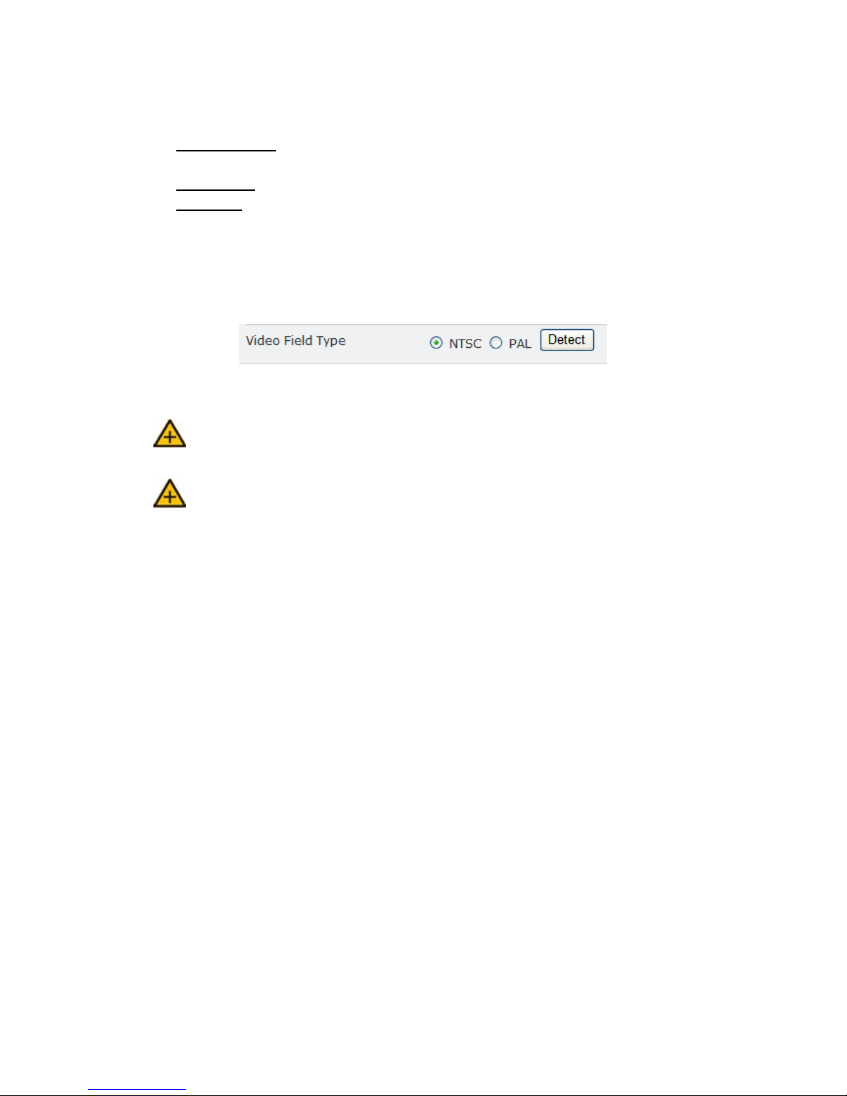
Video Servers also have an additional setting for NTSC and PAL.
Click Detect, and the video server will probe the camera and set the appropriate
value.
1M is recommended when using H.264; 1.5M is recommended when using
MPEG-4.
When mosaic or fragmentation occurs in the image, lower the frame rate or
assign another level of image quality.
Max Client
This function allows more than one user to have the access to the video stream.
The relationship between bit rates, resolution, and the client amount is inversely
related.
The maximum number of clients depends on the network bandwidth and the
required video quality. Values can range from 0 to 10.
14
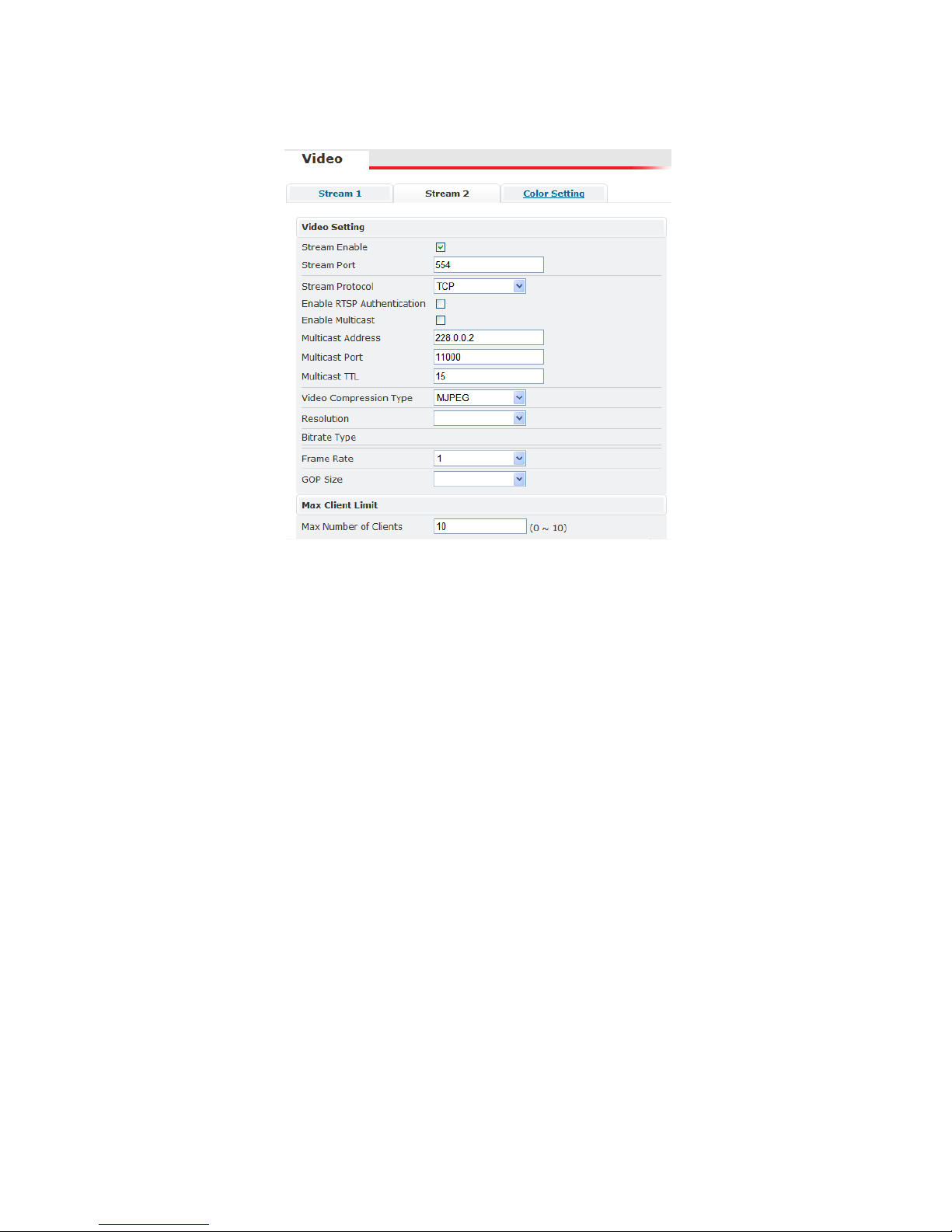
Stream 2
With the exception of the “Stream Enable” checkbox and the “Stream Port”, the
settings in stream 1 and 2 are the same (the above example do not reflect the
default values).
If stream 2 is enabled, then this stream can also be viewed in the Live View page.
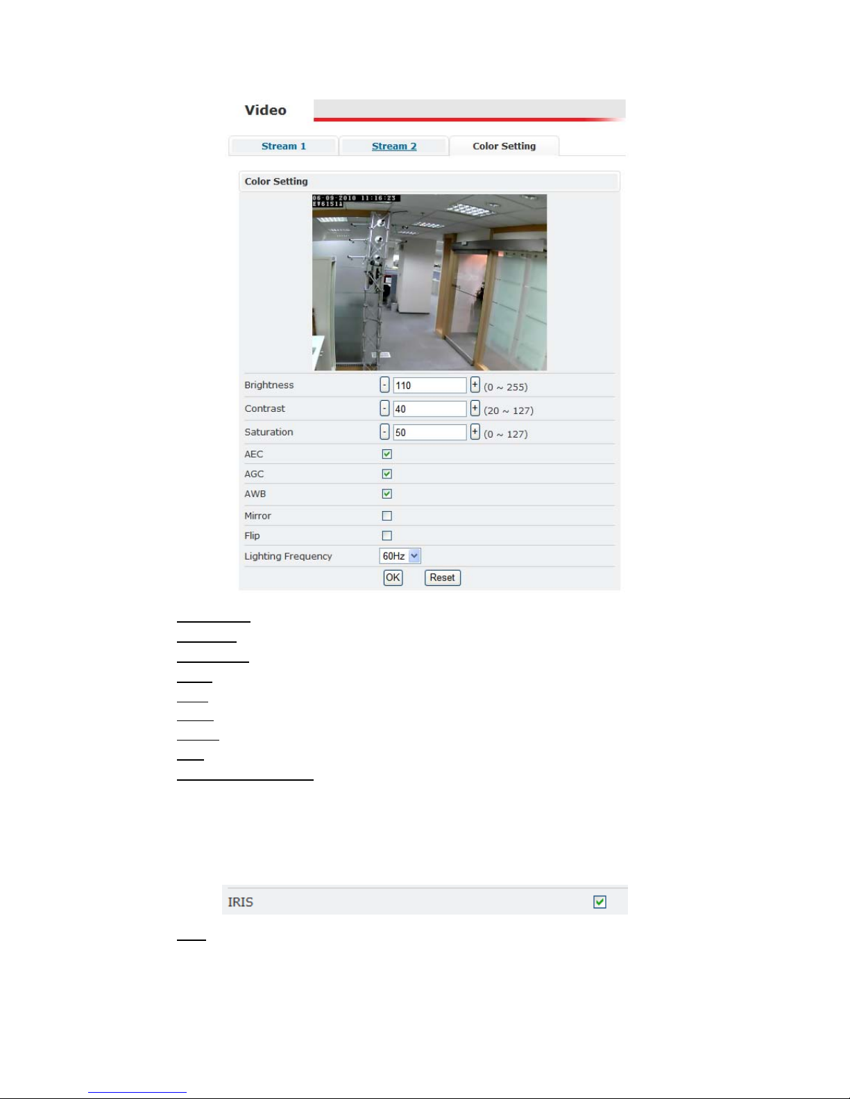
Color Setting
Note: Color Settings vary between camera models. The following screen shot is
from an IP camera with many of the video adjustment options for this firmware
version. Some models may have more or only have a subset of these settings.
The color settings allow making adjustments to video quality. Any adjustments
to a setting will automatically be displayed in the Color Setting preview window
after a few seconds.
Click OK to apply any changes or Reset to rollback any unsaved changes.
15
Brightness: Adjusts the brightness of the image.
Contrast: Adjusts the variation in the intensity of an image.
Saturation: Adjusts the intensity of color in the image.
AGC: Auto Gain Control; gain helps brighten dark images.
AEC: Enables auto exposure control.
AWB: Enables the automatic white balance control.
Mirror: Flip the im age horizontally.
Flip: Flip the image vertically.
Lighting Frequency: Adjusts for flickering effect caused by artificial lighting.
Options include 50Hz and 60Hz.
DC Iris
If the IP camera is using a lens with a DC iris (auto iris) then the auto iris
functionality will be displayed in the video settings.
IRIS
: check to enable auto iris
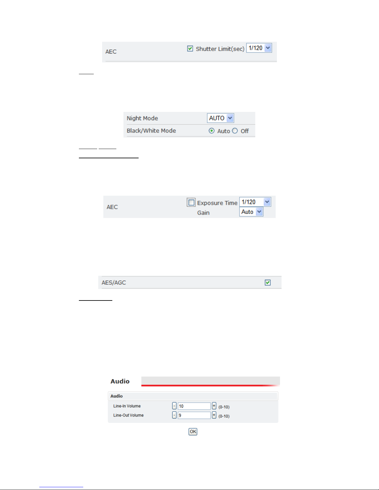
EV8150A Settings
The EV8150A also has the following AEC setting.
16
AEC: Enables auto exposure control.
Shutter Limit determines the minimum shutter speed for the AEC control.
EV6150A & EV8150A
These two cameras have the following additional settings.
Night mode: There are three modes to select: ON, OFF, AUTO.
Black/White Mode
: AUTO or OFF
EV6552R
AEC provides auto exposure control; however, manual settings are available if
the AEC is disabled.
Exposure Time values range from 1/60 to 1/32000.
Gain will brighten dark images. The Gain setting includes Auto, or it can be
manually set. Values range from 1x to 128x; higher values providing additional
brightening.
EV6153A
AES/AGC: click to enable.
EV6156A Color OSD Control
The EV6156A uses a special interface for adjusting video settings. Please refer to
the “EV6156A Color Settings” section for more information.
3.4 Audio
The audio settings control the level of audio in and out.
17
The values range from 0-10 (0 the minimum; 10 the maximum).
After changing the volume setting, click OK to apply the changes.
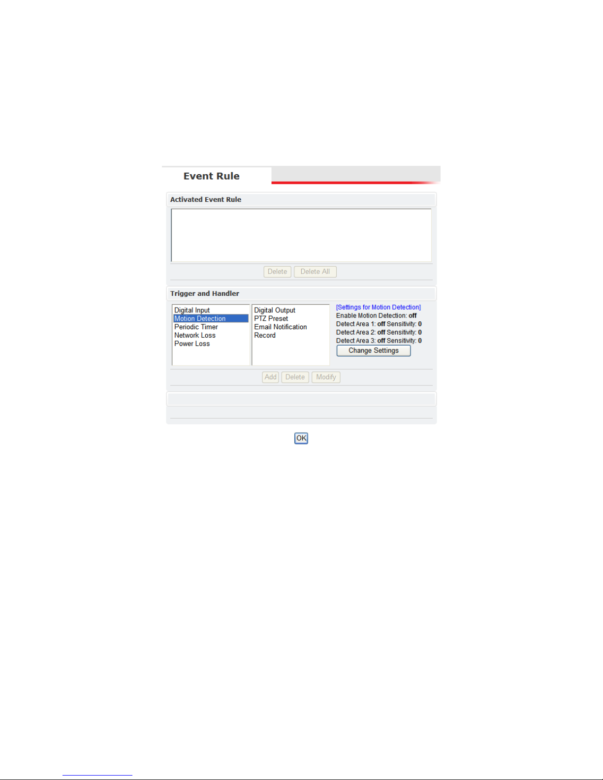
3.5 Event Rule
Etrovision IP cameras are capable of handling all standard events.
Events Handled
Digital Input: is a circuit which is defined as on (Normal Open (N.O.)) or
closed (Normal Close (N.C.))
Motion Detection: If a motion is detected in the defined areas, an event will be
triggered.
Periodic Timer: An event will be triggered following the schedule of the pre-
defined time interval. For example, if the time interval is set to 30 seconds, the
event will be triggered once every 30 seconds.
Network Loss: When network loss is detected, an event will be triggered.
Video Loss: When a video server detects a loss of video input from camera.
Power Loss: When system power loss is detected, and event will be triggered.
The e-mail notification includes the duration of the power loss.
Actions Triggered
Digital Output: Activate digital output.

18
E-mail Notification: E-mail can be sent based on occurrence of an event listed
out in “Rule Lists”.
Record: When an event is triggered, the system will record streaming video to
an FTP Server or NAS storage server.
Certain triggers (Digital Input, Motion Detection and Periodic Timer) also have
settings related to that specific event. Below highlights event settings related to
the Motion Detection trigger.
Events and Actions
The following table lists the various events, or triggers, and the available
methods of handling each trigger
Trigger/Event Handler/Action
Digital Input Digital Output
PTZ Preset*
Email Notification
Record
Motion Detection Digital Output
PTZ Preset1
Email Notification
Record
Periodic Timer Digital Output
PTZ Preset*
Email Notification
Network Loss Digital Output
Video Loss2 Digital Output
Email Notification
Power Loss Email Notification
1
PTZ Preset is only available for those models that support PTZ functionality.
2
Video Loss is a video server event; IP cameras will not list this event.
19
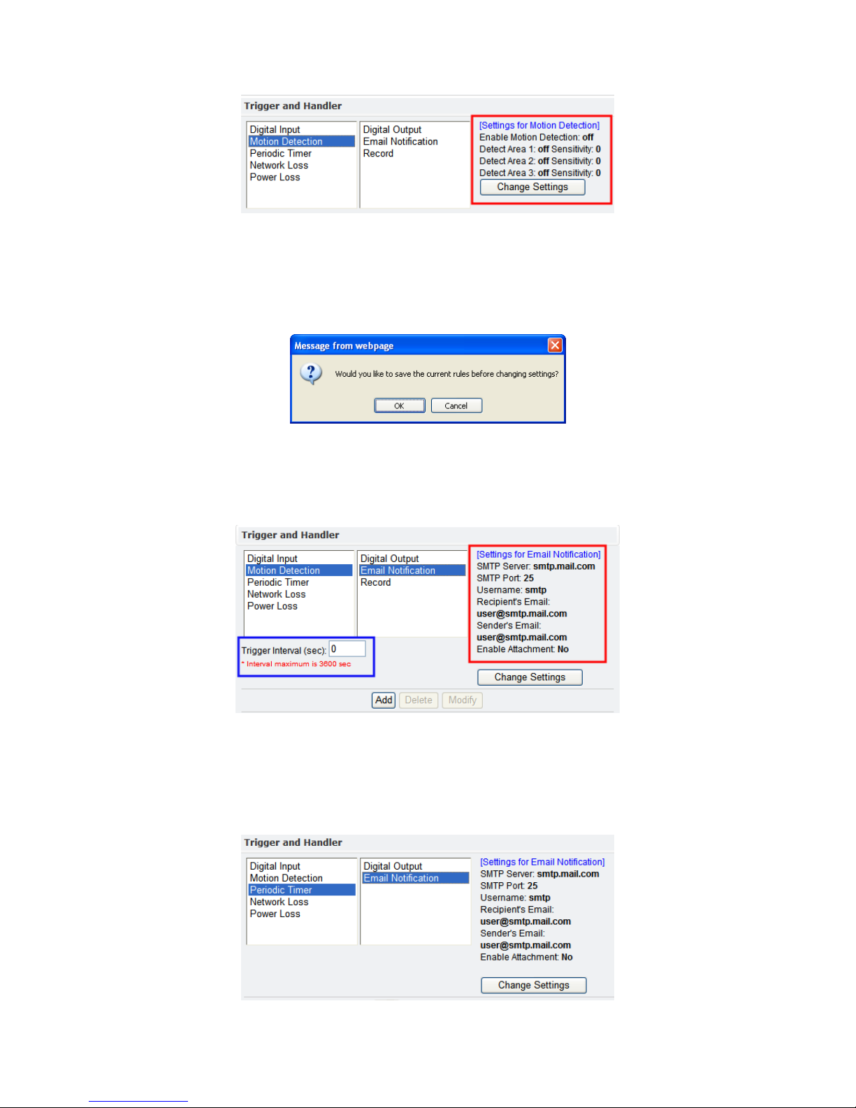
These additional trigger settings also correspond to the settings in the “Trigger
Setup” configuration view (See “Trigger Setup” for more information).
By clicking “Change Settings”, the browser window will be redirected to the
corresponding section in the configuration view (i.e. SMTP/FTP). The user will
first be asked about saving, or activating, the rule.
OK saves the rule; Cancel doesn’t save the rule. In either instance, the browser
will then be redirected to the corresponding configuration page.
In addition, the Handler actions also have additional settings displayed. Below is
the Email Notification handling action for the Motion Detection trigger.
The area highlighted in red is settings which can also be set via the “SMTP/FTP”
configuration view. However, the area highlighted in blue, “Trigger Interval”, is
a setting specific to the Motion Detection/Record handler; other Email
Notification handler actions may or may not have the “Trigger Interval” setting.
Below is an example of an Email Notification handler not using this setting.
20
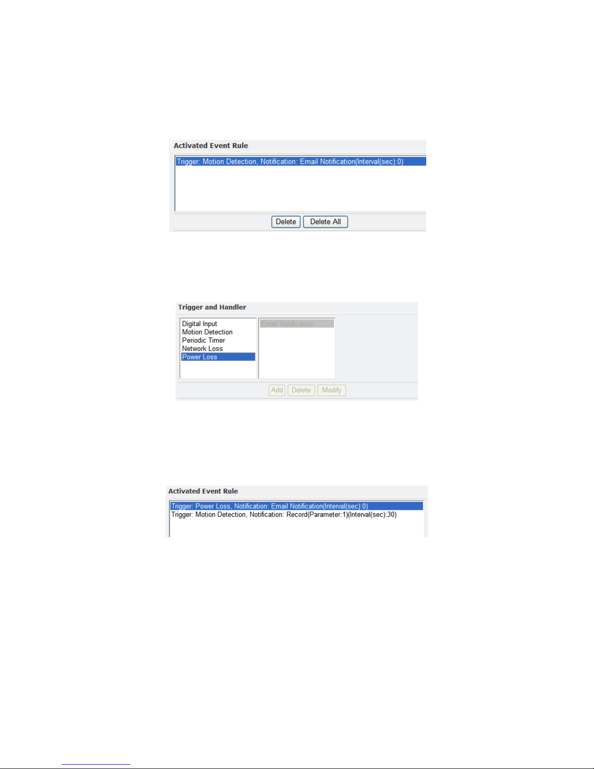
Activating Events
To activate an event, first select the event and corresponding actions. Next press
ADD button to activate the event; the event will be added to the “Activated
Event Rule” pane.
Lastly, click the OK button located at the bottom of the page to save the changes.
The activated event handler will be disabled in the “Trigger and Handler” pane.
The following shows the Power Loss/Email Notification has been disabled after
activating this event.
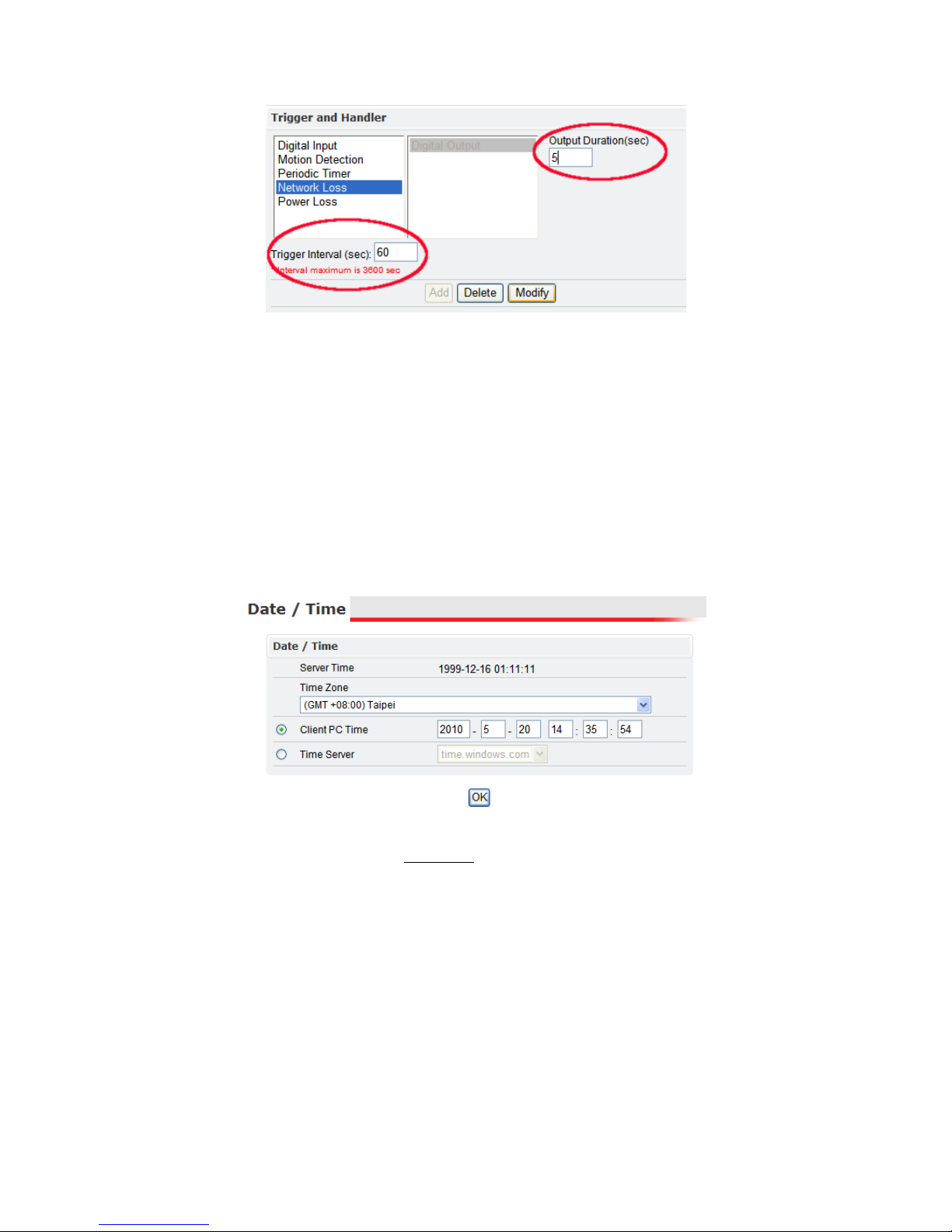
Modifying Activated Event Rules
To modify an event that has already been activated, first highlight the event in
the “Activated Event Rule” pane. Below the Network Loss event has been
highlighted for modification.
In the “Trigger and Handler” pane, the current settings for the activated event
are displayed. These can be changed as has been done below in the red
highlighted areas.
21
After making any desired changes, click Modify to see the changes in the
“Activated Event Rule” pane. Lastly, click OK at the bottom of the page to apply
the changes.
Deleting Events
To remove an event, select the event in the “Activated Event Rule” list, then click
the Delete. Next click OK at the bottom of the page to save the changes.
Clicking Delete All removes all the events in the “Activated Event Rule” list.
3.6 Date & Time
The “Server Time” displays a snapshot of the time as it was when the page was
accessed. The time displayed here will not increment.
The “Time Zone” drop down box offers a selection of time zones to apply to the
IP camera.
Client PC Time
The “Client PC Time” is used to synchronize the IP camera with the time of the
PC accessing the Settings page. “Client PC Time” will display the current time of
the PC.
To synchronize the camera with the PC time, choose the “Client PC Time” option
if not already selected and click OK at the bottom of the page.
 Loading...