

Page 1

IP Camera & Video Server
User’s Manual
Firmware Version 1.9.5
Document Version 1.4
Page 2

About This Guide
The User’s Manual provides functionality and instructions for Etrovision’s IP
cameras and video servers employing firmware version 1.9.5.
Before Using the IP Camera/Video Server
Check the PC requirements
Review the OS platform requirements
Read an special and import precautionary information
Having basic knowledge of network setup and configuration will be helpful
Important Announcements
NOTE: This icon represents a tip for operation.
CAUTION: This icon stands for an action that could affect an operation or mildly
impair the system.
WARNING: This icon indicates an action that will likely impair the system.
Disclaimer
© 2007 Etrovision Technology. All rights reserved.
EtroLink™ & AnyUSB™ are trademarks of Etrovision Technology; other product or
service names mentioned herein are the trademarks of their respective owners.
Information contained in this document may be superseded by updates. No
representation or warranty is given and no liability is assumed by Etrovision
Technology with respect to the accuracy or use of the information, or infringement of
patents or other intellectual property rights. No licenses are conveyed, implicitly or
otherwise, under any intellectual property rights.
Page 3

1 INTRODUCTION ...............................................................................1
1.1 Camera Model Differences.......................................................................... 1
2 THE LIVE VIEW.................................................................................2
2.1 OSD (On-Screen Display)........................................................................... 2
2.2 Setup, Snapshot and Record Video............................................................3
2.3 Video........................................................................................................... 3
2.4 Audio........................................................................................................... 3
2.5 SD Status.................................................................................................... 3
2.6 Control (PTZ Controls)................................................................................ 4
EV6250A Speed Dome...............................................................................5
2.7 Camera Info and Digital Output...................................................................5
Camera Info ................................................................................................ 5
Digital Output .............................................................................................. 6
3 THE SETTINGS PAGE – BASIC.......................................................7
3.1 Status.......................................................................................................... 9
3.2 Network....................................................................................................... 9
Static IP.......................................................................................................9
Dynamic IP Address .................................................................................. 10
PPPoE Settings......................................................................................... 11
UPnP.........................................................................................................11
3.3 Video......................................................................................................... 12
Stream 1....................................................................................................12
Video Setting.............................................................................................12
Max Client................................................................................................. 13
Stream 2....................................................................................................14
Color Setting ............................................................................................. 14
3.4 Audio......................................................................................................... 16
3.5 Event Rule................................................................................................. 17
Events Handled......................................................................................... 17
Actions Triggered......................................................................................17
Events and Actions....................................................................................18
Activating Events....................................................................................... 20
Modifying Activated Event Rules...............................................................20
Deleting Events.........................................................................................21
3.6 Date & Time .............................................................................................. 21
Client PC Time..........................................................................................21
Time Server............................................................................................... 22
Page 4

3.7 OSD (On-Screen Display)......................................................................... 22
4 THE SETTINGS PAGE – EXPERT .................................................24
4.1 PTZ Control (Pan, Tilt, Zoom)................................................................... 24
4.2 Port............................................................................................................25
4.3 DDNS (Dynamic DNS).............................................................................. 25
4.4 SMTP/FTP ................................................................................................ 26
Remote SMTP Setup ................................................................................27
Remote FTP Setup....................................................................................28
4.5 Trigger Setup.............................................................................................28
Digital Input............................................................................................... 29
Periodic Timer...........................................................................................29
Motion Detection .......................................................................................29
Video Loss ................................................................................................ 31
4.6 Pre/Post Setting ........................................................................................32
4.7 SD Card .................................................................................................... 32
4.8 NAS Setting (Network Attached Storage).................................................. 33
4.9 Account..................................................................................................... 34
The Administrator Account........................................................................ 35
User Accounts...........................................................................................36
Guest Permission...................................................................................... 36
4.10 Security..................................................................................................... 37
Network Security.......................................................................................38
Power LED................................................................................................41
4.11 Maintenance.............................................................................................. 41
Language.................................................................................................. 42
Firmware Update....................................................................................... 42
System Configuration (Backup / Restore)................................................. 44
Factory Default..........................................................................................45
5 REBOOT..........................................................................................46
6 SYSTEM LOG..................................................................................47
7 LOGOUT..........................................................................................48
8 WIRELESS CONNECTIVITY...........................................................49
8.1 Web Interface Configuration...................................................................... 49
8.2 EtroLink™ USB Configuration Port ...........................................................53
9 EV6156A COLOR SETTINGS.........................................................57
9.1 Menu Options............................................................................................59
IRIS........................................................................................................... 59
AGC/SENS................................................................................................ 59
Page 5

BACKLIGHT..............................................................................................59
WHITE BALANCE..................................................................................... 60
GAMMA/ENHANCE.................................................................................. 60
IR-SET ...................................................................................................... 60
DIGITAL ZOOM ........................................................................................ 60
H/V REVERSE..........................................................................................60
MOTION DETECT.....................................................................................61
LANGUAGE.............................................................................................. 61
MASK........................................................................................................ 61
OSD ..........................................................................................................61
CROSS LINE/FREEZE .............................................................................62
POSI/NEGA .............................................................................................. 62
DIGITAL OUT............................................................................................ 62
TITLE ........................................................................................................62
PRIORITY................................................................................................. 62
PRESET/PHASE....................................................................................... 63
10 ADDITIONAL INFORMATION .........................................................64
11 GLOSSARY.....................................................................................65
Page 6

1
1 INTRODUCTION
This document covers functionality and usage of the web interface for IP cameras
and video servers with firmware version 1.9.5. Specific model information can be
found in the model specification which can be found in the Installation Guide for the
corresponding model.
For the sake of convenience, “IP camera” and “camera” will be used to reference
both IP cameras and video servers. “Video server” will be used where there is a need
for clarity.
1.1 Camera Model Differences
Although most of the operations and functions being the same amongst models,
there are some differences. Differences are highlighted where applicable.
The following table highlights primary functionality that differs between models.
These differences will determine if certain items and settings will exist in the Live
View and/or Settings page.
SD
Card
PTZ
Capable
WiFi
Color
OSD
EtroLink
Box
EV6150A x x x x
EV6151A x x x x
EV6153A x x x x
EV6156A x x x x x
Dome
EV6551A x
EV6552A x
EV6552R
Megapixel
EV8150A x x x x
Outdoor
EV6353A x
EV6355A x
EV6356A x
Speed Dome
EV6250A x x
Video Server
EV3151 x x
EV3151A x x x
For example, if a camera isn’t PTZ capable (e.g. EV6552A), then the PTZ controls will
not be present in the Live View page and the PTZ settings option will not be present
in the Settings page.
Page 7
2
2 THE LIVE VIEW
The IP camera web interface is made up of two main pages: the Live View page and
the Settings page. The Live View provides the current display from the IP camera
along with selected settings, configuration and functionality.
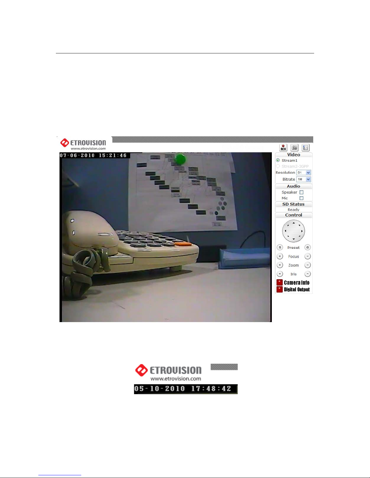
After logging into the IP camera via the browser, the user is first presented with the
Live View page.
Below is an example of the Live View page. Following the screenshot is a discussion
of the different areas within the Live View page.
2.1 OSD (On-Screen Display)
In the top left corner is the OSD (On-Screen Display).
By default, the date and time are displayed in the format MM-DD-YYYY
HH24:MI:SS; the camera name can also be displayed (see “OSD” section for
information on altering the OSD settings).
Page 8
3
2.2 Setup, Snapshot and Record Video
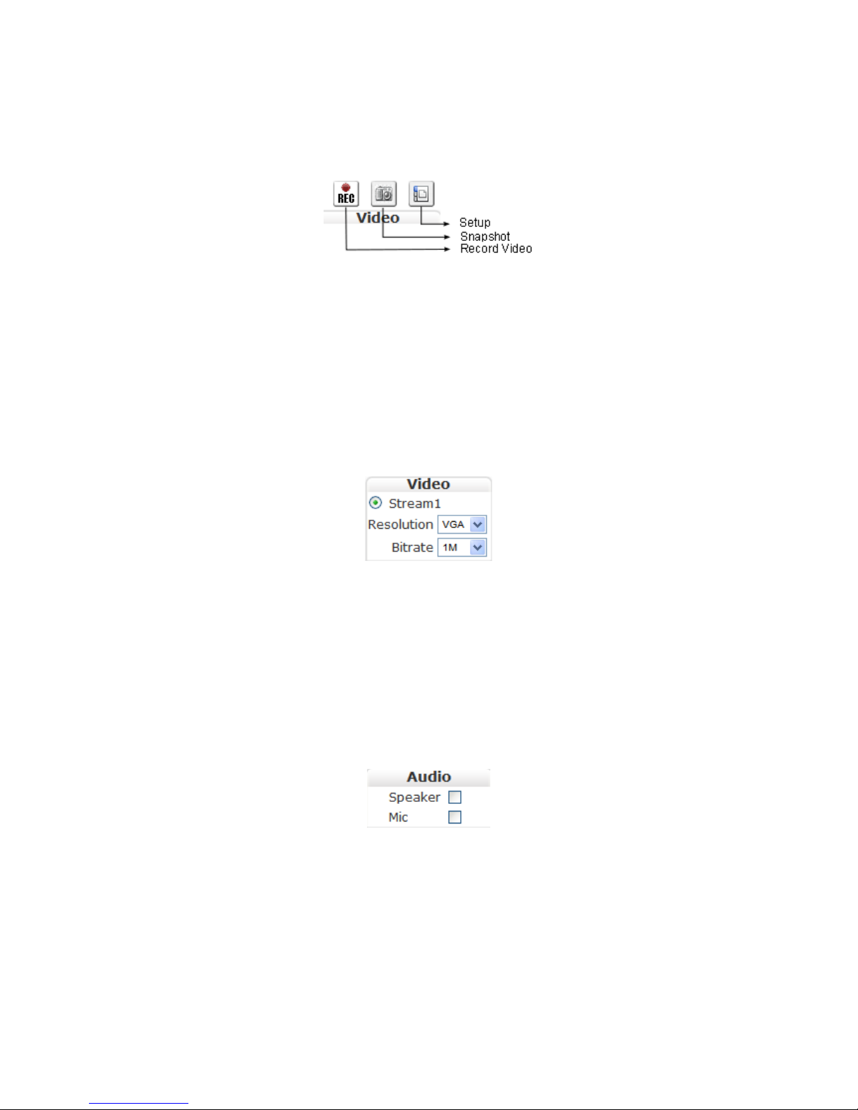
In the top right corner of the screen are three controls.
“Setup” switches from the Live View page to the administration configuration
page where most of the IP camera configuration is performed.
“Snapshot” can be used to take snapshot pictures. The files are stored locally
on the PC.
“Record Video” starts and stops recording of video. The files are stored
locally on the PC.
2.3 Video
Below the Setup/Snapshot/Record controls are the video and resolution controls.
“Stream2” will also be displayed if it has been enabled (see the Settings Page
“Video” section for more information).
The resolution and bitrate can be modified here. In the drop down box, choose
one of the options.
Changes take place a few seconds after modification; the image on the screen
might briefly pause while changes are implemented.
2.4 Audio
The “Audio” check boxes enable/disable speaker and microphone (Mic)
capabilities. The appropriate cables need to be connected into the back of the
camera. (See the “Audio” section for more information).
2.5 SD Status
Note: Dome, Outdoor and Speed Dome models do not have SD Card
functionality as of this firmware version.
Page 9
4
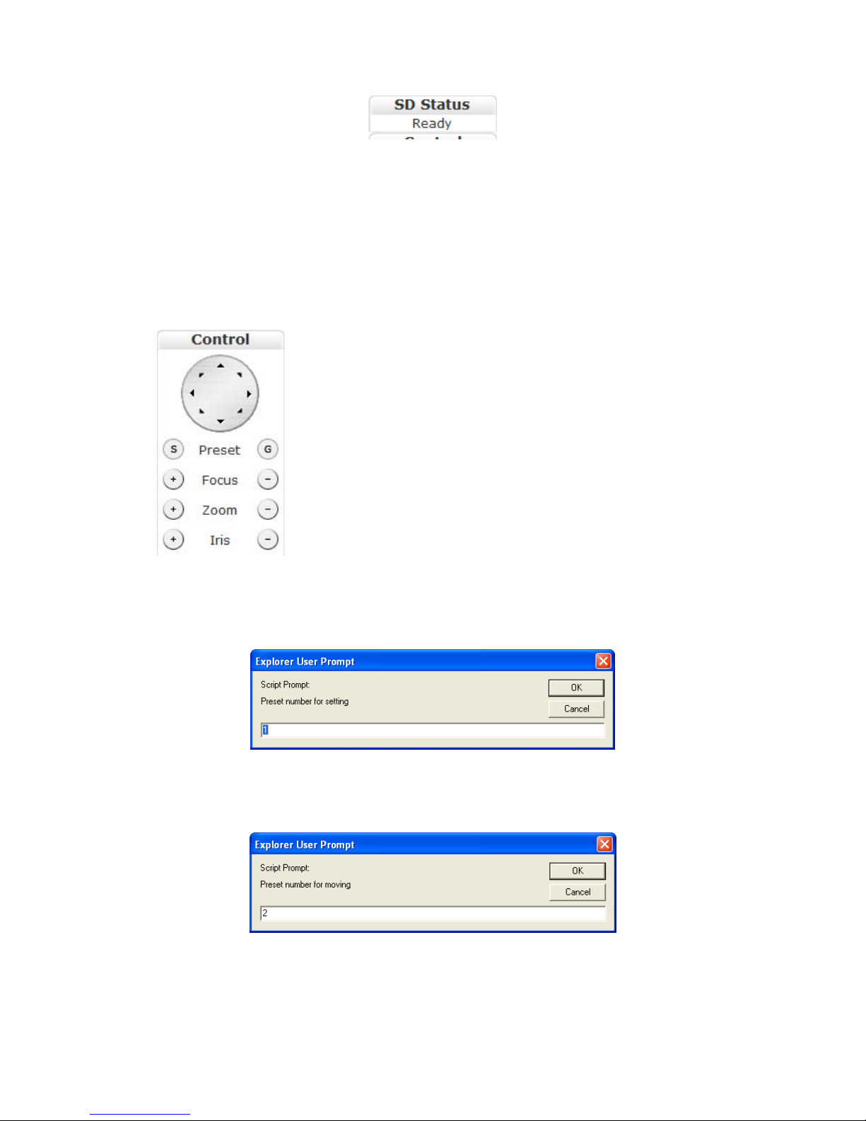
The “SD Status” is the secure digital (SD) card status. If no card is present then
the status will be “Invalid”. See the “SD Card” section for more information.
2.6 Control (PTZ Controls)
Note: Dome and Outdoor models do not have PTZ functionality as of this
firmware version.
The Control section allows operating the PTZ controls from the Live View.
The round dial with directional arrows controls the
directional movement of the camera.
“Preset” is used for configuring and using camera directional
presets. There are two buttons: S and G.
Focus, zoom and iris controls are modified using the + and –
buttons.
S is used to set a specific location view. First position the camera to view a
specific area. Next click S which displays a window prompting the ID to assign
the specific preset.
Enter an alphanumeric ID for a specific preset and click OK.
G is used to move the camera to a specific preset. Click G, enter the desired
preset ID and click OK.
Page 10
5
EV6250A Speed Dome
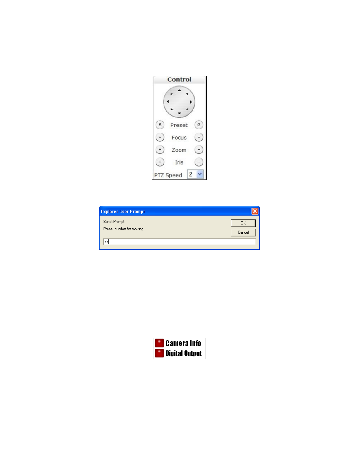
The EV6250A has some slight differences. Below are the PTZ controls in the
EV6250A.
The “PTZ Speed” controls how fast PTZ movement occurs. Values range from 1-6.
The EV6250A has a preconfigured PTZ setting number, 98.
This setting will result in the camera continuously panning 360° on the current
axis.
2.7 Camera Info and Digital Output
Camera Info
The 2 buttons on the bottom right are “Camera Info” and “Digital Output”.
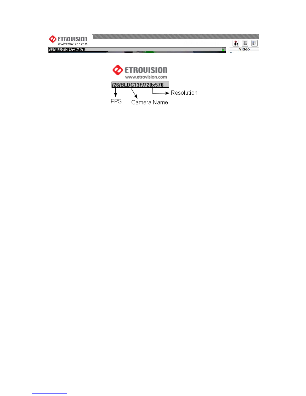
The “Camera Info” button displays video information such as frame rate (fps),
model name, and resolution. This information is displayed where the OSD
information is normally displayed, the top left corner.
Below are two screenshots displaying when the “Camera Info” button is enabled.
Note that the OSD information is no longer viewable when the button is enabled.
Page 11
6
Digital Output
The “Digital Output” control is a toggle button that sends a Digital Out signal.
This functionality is available if a corresponding device is connected to the IP
camera using the digital I/O terminal.
Page 12
7
3 THE SETTINGS P AGE – BASIC
The web interface is made up of two main pages: the Live View page and the
Settings page. The Live View page interface was introduced in the previous section.
The Settings page is primarily used for viewing and configuring the IP camera’s
settings.
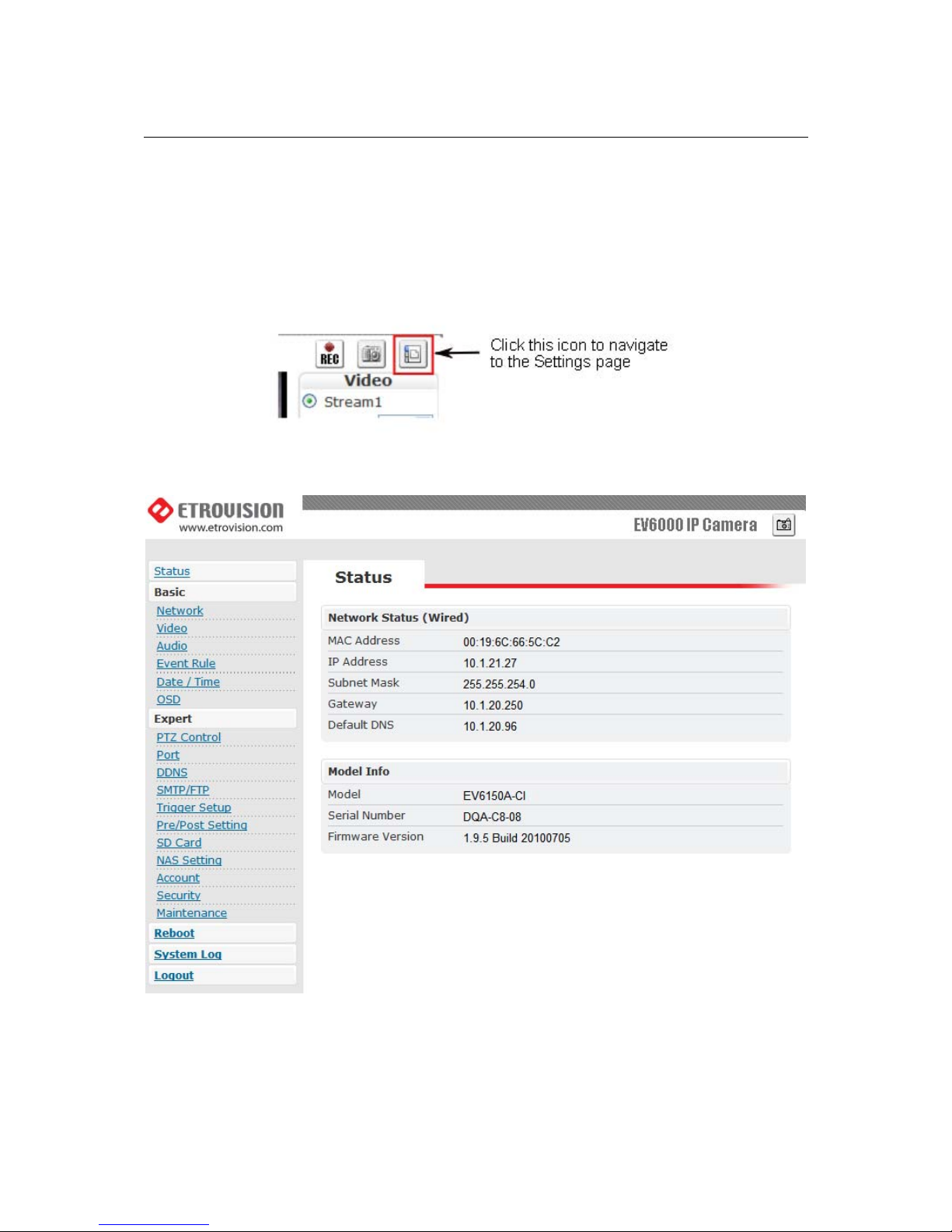
From the Live View page, click the Settings page icon at the top right side:
Below is a screenshot of the Settings page interface. The initial page displayed is the
“Status” page.
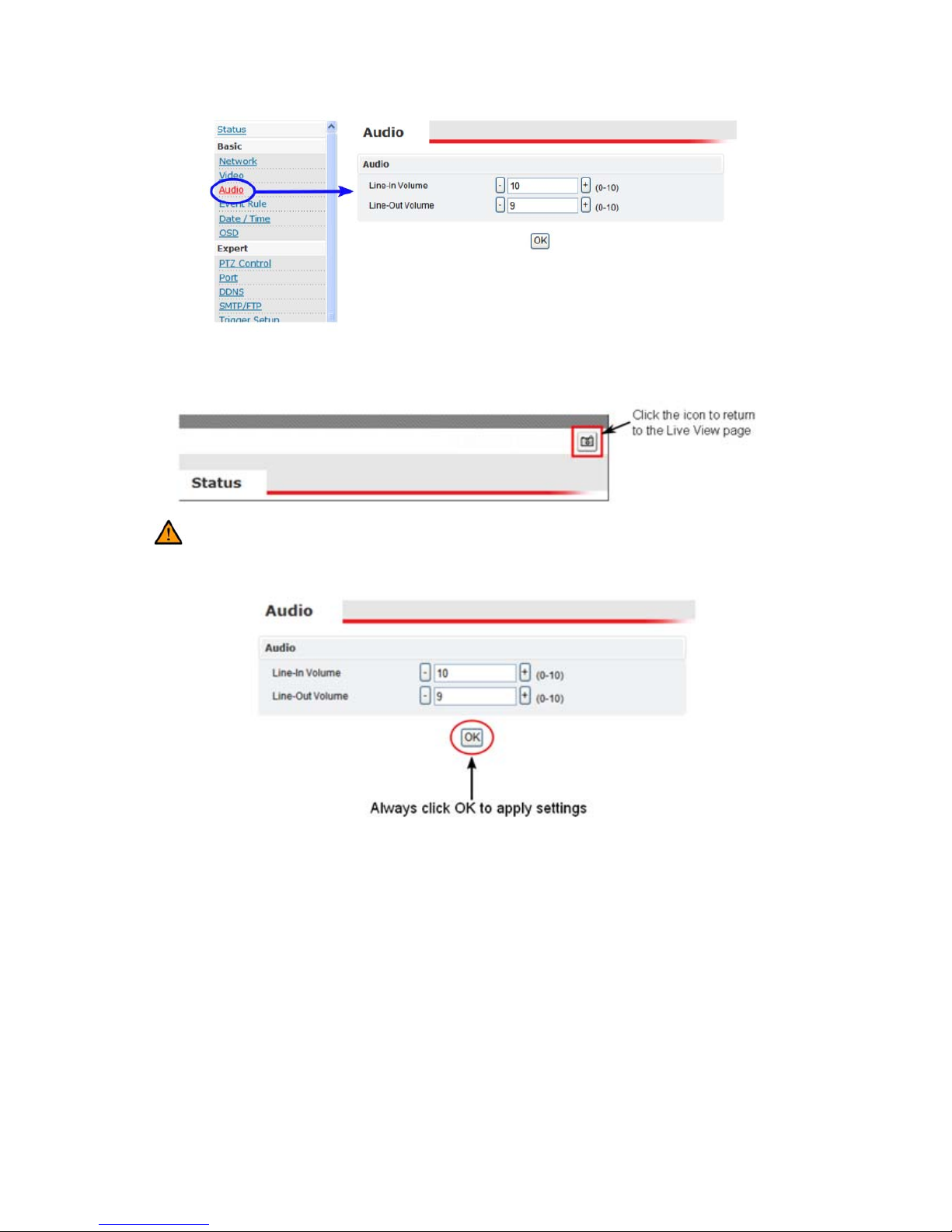
The left side of the page lists the different setting sections which can be viewed and
modified. For example, clicking “Audio” will display the “Audio” configuration
settings in the right pane.
Page 13
8
From the Settings page, click the Live View page icon (highlighted in red in the
upper right corner) to return to the Live View page.
Configuration changes in the Settings page require clicking the OK button.
Otherwise, changes will not be applied.
The following discusses the different basic configuration options within the Settings
page.
Page 14
9
3.1 Status
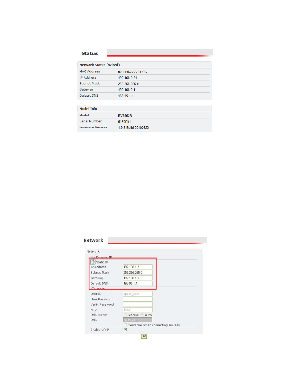
The Status page is always the initial page displayed when switching to the
configuration view. Various basic information related to the IP camera is
displayed here.
The page only displays information; no changes can be made here.
3.2 Network
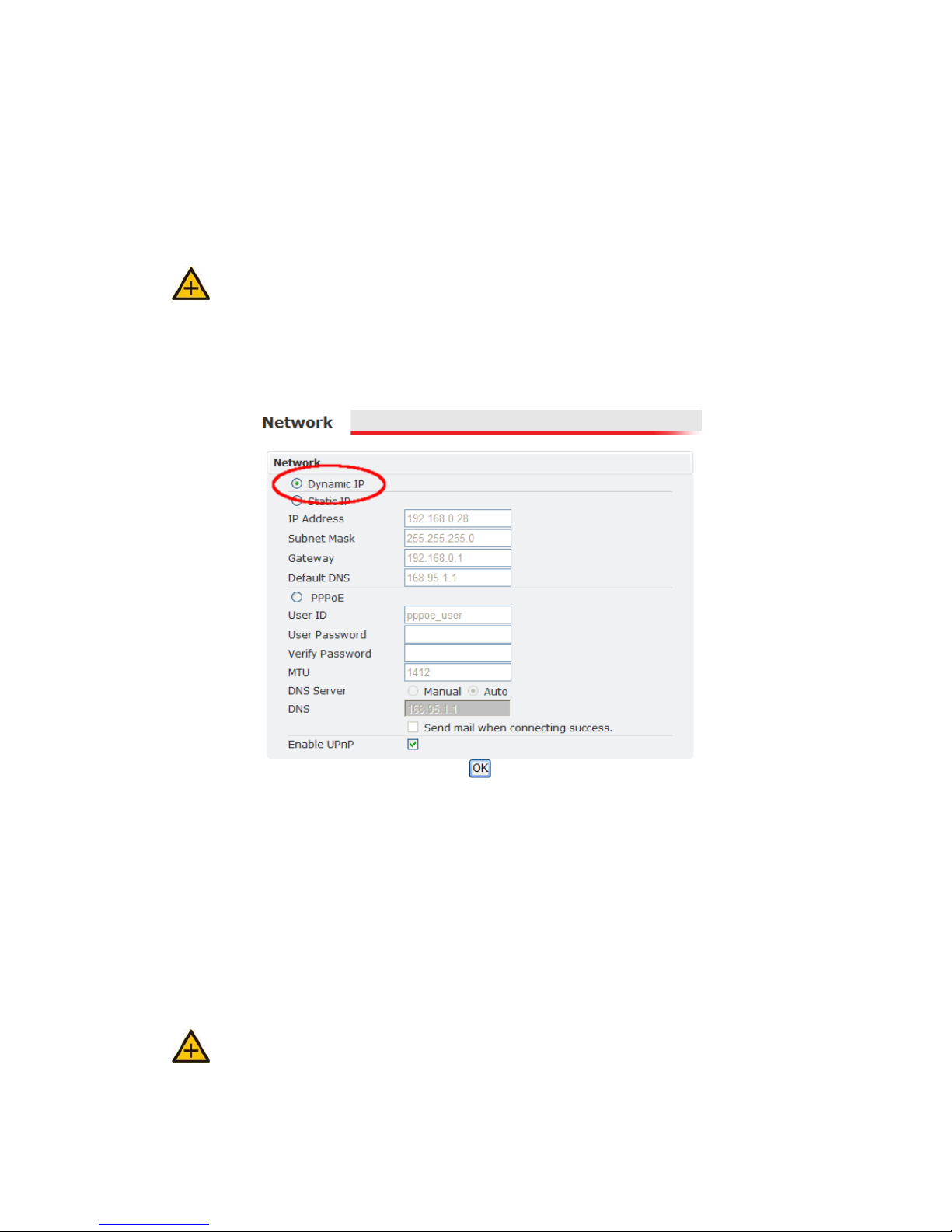
There are three available types of wired network connections available: STATIC,
DYNAMIC and, PPPoE.
Please confirm all network related settings with the network administrator prior
to making any changes.
Static IP
Page 15
10
1. Enter the IP Address.
2. Enter the Subnet Mask/Gateway/Default DNS
3. Be sure to press OK to save the new setting.
4. A window prompting a reboot will be displayed. Click OK to proceed with
the reboot (or Cancel if you wish to return to the Network settings).
5. A timer will countdown the approximate time for reboot to complete. The
page will be redirected to the live view page using the new IP address.
Use EtroScan™ to find the MAC addresses after reboot and ensure the IP
address is correct. If the IP was changed in web configuration, you must access
the initial login page using the new IP after the reboot.
Dynamic IP Address
1. Select DHCP
2. Press OK button
3. Reboot will be required and automatically triggered after pressing OK.
4. A window prompting a reboot will be displayed. Click OK to proceed with
reboot (or Cancel if you wish to return to the Network settings). A timer will
countdown the approximate time for reboot to complete.
The browser will likely not reload since the IP is uncertain. The new IP address
will likely need to be determined using EtroScan™ and the IP camera’s MAC
address. After determining the new IP address, use this IP address to access the
web interface.
Always use EtroScan™ to find the MAC addresses after reboot and double
check the IP address. Make sure the IP address is correct. If IP was changed in
web configuration, you cannot return to initial login page after reboot.
Page 16

11
PPPoE Settings
If the network supports PPPoE like xDSL, then PPPoE can also be used for
connectivity.
1. Select PPPoE
2. Enter the PPPoE ID and password.
3. Enter the MTU (Maximum transmission unit)
4. The DNS server can be manually set or “Auto” can be used to automatically
detect the DNS IP address.
If xDSL does not use static IP addresses, then DHCP should be used.
UPnP
To enable UPnP (Universal Plug and Play)connectivity, check the “Enable UPnP”
box. This will allow accessing the camera via UPnP connectivity from a computer.
Page 17
12
3.3 Video
Stream 1
Video Setting
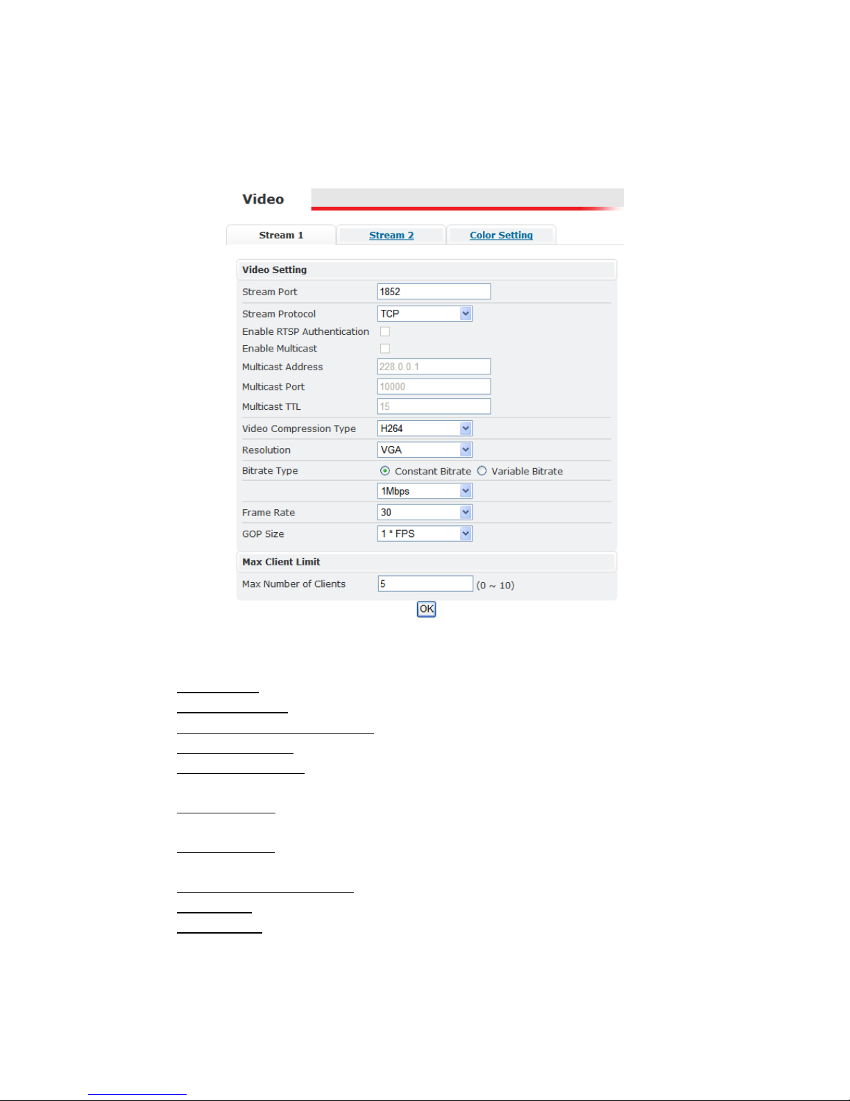
Stream Port: Stream 1 port value setting; 1852 is the default.
Stream Protocol
: TCP and UDP(RTP)
Enable RTSP Authentication
: option available if UDP(RTP) protocol selected
Enable Multicast
: option available if UDP(RTP) protocol selected
Multicast Address
: option available if multicasting enabled; the default value
is 228.0.0.1. Verify address with the network administrator before applying
Multicast Port: option available if multicasting enabled; the default value is
10000. Verify address with the network administrator before applying
Multicast TTL: TTL (Time To Live); option available if multicasting enabled;
the default value is 15
Video Compression Type: H264, MJEPG, MPEG-4
Resolution
: this setting can also be set from the live view page
Bitrate Type
: constant bit rates and variable bit rates. The Bitrate option is not
present when using MJPEG video compression
Constant values range 64Kbps to 4Mbps; 2Mbps is the default.
Page 18
13
Variable values range from 15 to 51; this value is relative quality of video. 15
represents highest quality video, and 51 the lowest quality video.
Image Quality: not displayed in above screenshot; only available when using
MJPEG video compression
Frame Rate: (Frames per Second) values range from 1 to 30
GOP Size: GOP (Group Of Pictures); this function is designed for adjusting
the ratio between “I” frames and “P” frames.
This option is not available when using MJPEG video compression.
A higher GOP size (i.e. 4 * FPS) results in lower bandwidth consumption,
while a lower GOP size provides better picture quality.
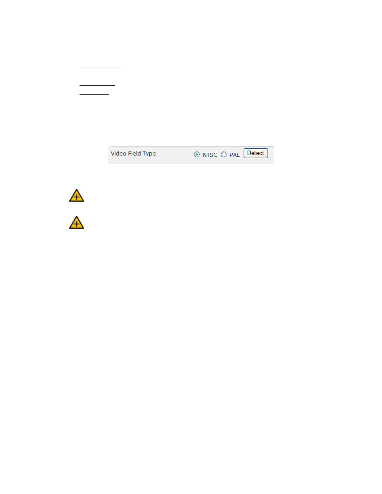
Video Servers also have an additional setting for NTSC and PAL.
Click Detect, and the video server will probe the camera and set the appropriate
value.
1M is recommended when using H.264; 1.5M is recommended when using
MPEG-4.
When mosaic or fragmentation occurs in the image, lower the frame rate or
assign another level of image quality.
Max Client
This function allows more than one user to have the access to the video stream.
The relationship between bit rates, resolution, and the client amount is inversely
related.
The maximum number of clients depends on the network bandwidth and the
required video quality. Values can range from 0 to 10.
Page 19
14
Stream 2
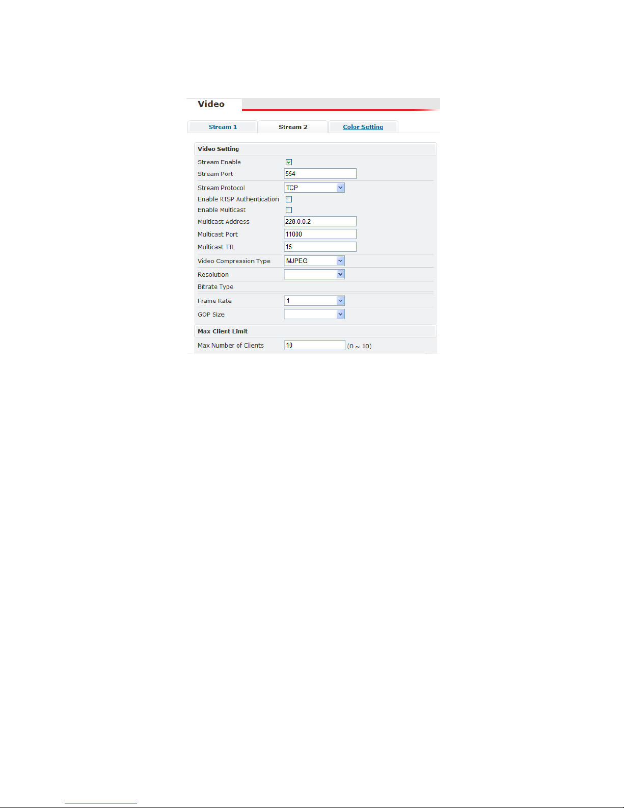
With the exception of the “Stream Enable” checkbox and the “Stream Port”, the
settings in stream 1 and 2 are the same (the above example do not reflect the
default values).
If stream 2 is enabled, then this stream can also be viewed in the Live View page.
Color Setting
Note: Color Settings vary between camera models. The following screen shot is
from an IP camera with many of the video adjustment options for this firmware
version. Some models may have more or only have a subset of these settings.
The color settings allow making adjustments to video quality. Any adjustments
to a setting will automatically be displayed in the Color Setting preview window
after a few seconds.
Click OK to apply any changes or Reset to rollback any unsaved changes.
Page 20

15
Brightness: Adjusts the brightness of the image.
Contrast: Adjusts the variation in the intensity of an image.
Saturation: Adjusts the intensity of color in the image.
AGC: Auto Gain Control; gain helps brighten dark images.
AEC: Enables auto exposure control.
AWB: Enables the automatic white balance control.
Mirror: Flip the im age horizontally.
Flip: Flip the image vertically.
Lighting Frequency: Adjusts for flickering effect caused by artificial lighting.
Options include 50Hz and 60Hz.
DC Iris
If the IP camera is using a lens with a DC iris (auto iris) then the auto iris
functionality will be displayed in the video settings.
IRIS
: check to enable auto iris
EV8150A Settings
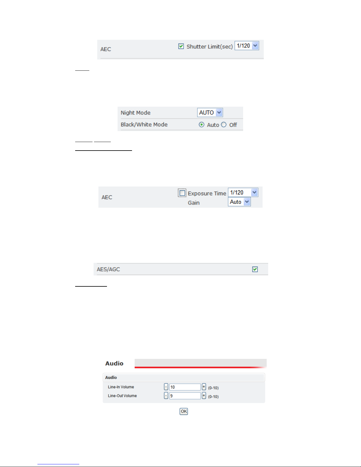
The EV8150A also has the following AEC setting.
Page 21
16
AEC: Enables auto exposure control.
Shutter Limit determines the minimum shutter speed for the AEC control.
EV6150A & EV8150A
These two cameras have the following additional settings.
Night mode: There are three modes to select: ON, OFF, AUTO.
Black/White Mode
: AUTO or OFF
EV6552R
AEC provides auto exposure control; however, manual settings are available if
the AEC is disabled.
Exposure Time values range from 1/60 to 1/32000.
Gain will brighten dark images. The Gain setting includes Auto, or it can be
manually set. Values range from 1x to 128x; higher values providing additional
brightening.
EV6153A
AES/AGC: click to enable.
EV6156A Color OSD Control
The EV6156A uses a special interface for adjusting video settings. Please refer to
the “EV6156A Color Settings” section for more information.
3.4 Audio
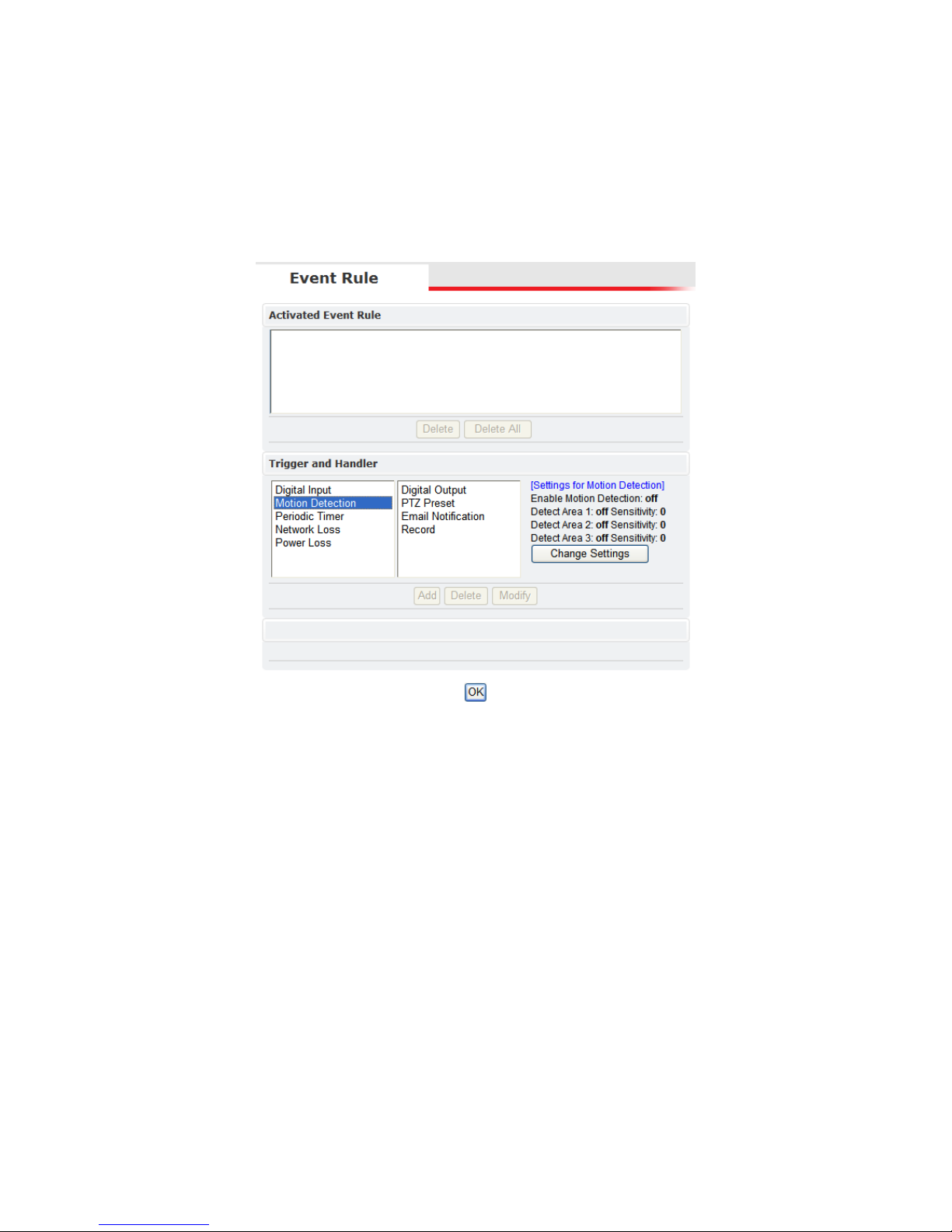
The audio settings control the level of audio in and out.
Page 22
17
The values range from 0-10 (0 the minimum; 10 the maximum).
After changing the volume setting, click OK to apply the changes.
3.5 Event Rule
Etrovision IP cameras are capable of handling all standard events.
Events Handled
Digital Input: is a circuit which is defined as on (Normal Open (N.O.)) or
closed (Normal Close (N.C.))
Motion Detection: If a motion is detected in the defined areas, an event will be
triggered.
Periodic Timer: An event will be triggered following the schedule of the pre-
defined time interval. For example, if the time interval is set to 30 seconds, the
event will be triggered once every 30 seconds.
Network Loss: When network loss is detected, an event will be triggered.
Video Loss: When a video server detects a loss of video input from camera.
Power Loss: When system power loss is detected, and event will be triggered.
The e-mail notification includes the duration of the power loss.
Actions Triggered
Digital Output: Activate digital output.
Page 23

18
E-mail Notification: E-mail can be sent based on occurrence of an event listed
out in “Rule Lists”.
Record: When an event is triggered, the system will record streaming video to
an FTP Server or NAS storage server.
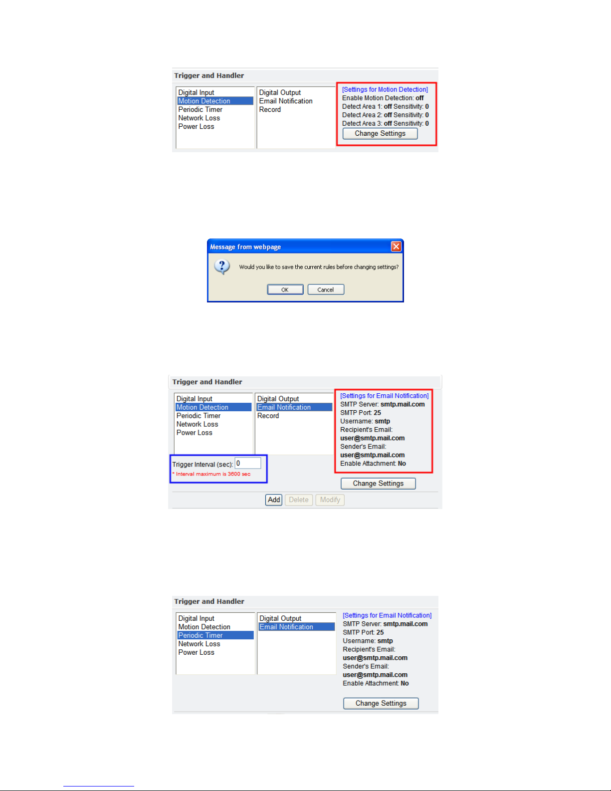
Certain triggers (Digital Input, Motion Detection and Periodic Timer) also have
settings related to that specific event. Below highlights event settings related to
the Motion Detection trigger.
Events and Actions
The following table lists the various events, or triggers, and the available
methods of handling each trigger
Trigger/Event Handler/Action
Digital Input Digital Output
PTZ Preset*
Email Notification
Record
Motion Detection Digital Output
PTZ Preset1
Email Notification
Record
Periodic Timer Digital Output
PTZ Preset*
Email Notification
Network Loss Digital Output
Video Loss2 Digital Output
Email Notification
Power Loss Email Notification
1
PTZ Preset is only available for those models that support PTZ functionality.
2
Video Loss is a video server event; IP cameras will not list this event.
Page 24
19
These additional trigger settings also correspond to the settings in the “Trigger
Setup” configuration view (See “Trigger Setup” for more information).
By clicking “Change Settings”, the browser window will be redirected to the
corresponding section in the configuration view (i.e. SMTP/FTP). The user will
first be asked about saving, or activating, the rule.
OK saves the rule; Cancel doesn’t save the rule. In either instance, the browser
will then be redirected to the corresponding configuration page.
In addition, the Handler actions also have additional settings displayed. Below is
the Email Notification handling action for the Motion Detection trigger.
The area highlighted in red is settings which can also be set via the “SMTP/FTP”
configuration view. However, the area highlighted in blue, “Trigger Interval”, is
a setting specific to the Motion Detection/Record handler; other Email
Notification handler actions may or may not have the “Trigger Interval” setting.
Below is an example of an Email Notification handler not using this setting.
Page 25
20
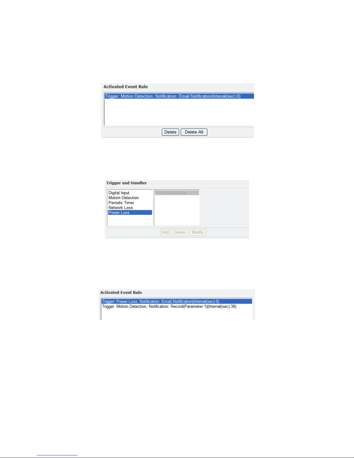
Activating Events
To activate an event, first select the event and corresponding actions. Next press
ADD button to activate the event; the event will be added to the “Activated
Event Rule” pane.
Lastly, click the OK button located at the bottom of the page to save the changes.
The activated event handler will be disabled in the “Trigger and Handler” pane.
The following shows the Power Loss/Email Notification has been disabled after
activating this event.
Modifying Activated Event Rules
To modify an event that has already been activated, first highlight the event in
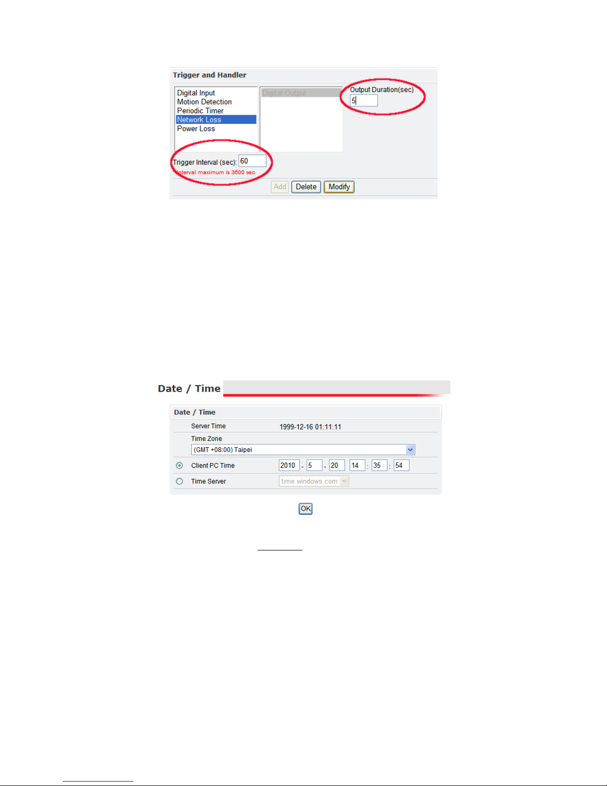
the “Activated Event Rule” pane. Below the Network Loss event has been
highlighted for modification.
In the “Trigger and Handler” pane, the current settings for the activated event
are displayed. These can be changed as has been done below in the red
highlighted areas.
Page 26
21
After making any desired changes, click Modify to see the changes in the
“Activated Event Rule” pane. Lastly, click OK at the bottom of the page to apply
the changes.
Deleting Events
To remove an event, select the event in the “Activated Event Rule” list, then click
the Delete. Next click OK at the bottom of the page to save the changes.
Clicking Delete All removes all the events in the “Activated Event Rule” list.
3.6 Date & Time
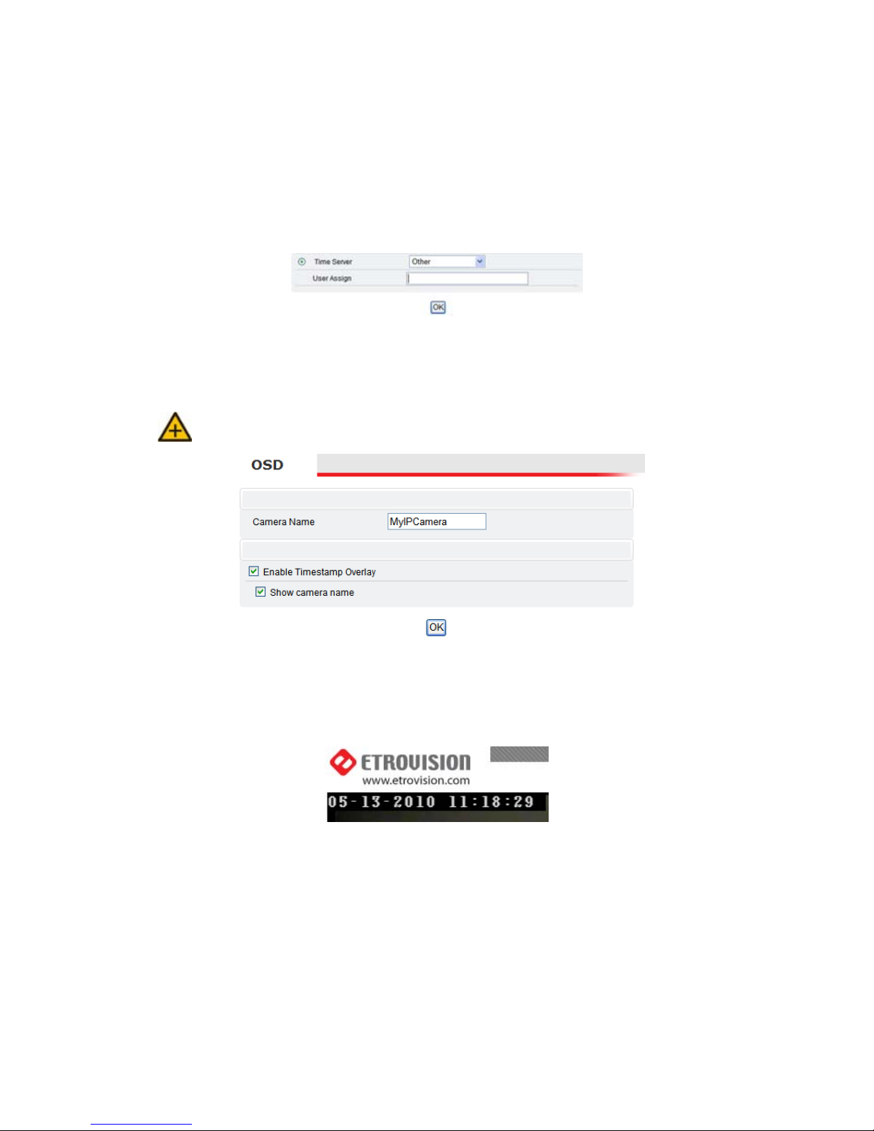
The “Server Time” displays a snapshot of the time as it was when the page was
accessed. The time displayed here will not increment.
The “Time Zone” drop down box offers a selection of time zones to apply to the
IP camera.
Client PC Time
The “Client PC Time” is used to synchronize the IP camera with the time of the
PC accessing the Settings page. “Client PC Time” will display the current time of
the PC.
To synchronize the camera with the PC time, choose the “Client PC Time” option
if not already selected and click OK at the bottom of the page.
Page 27
22
Time Server
A Time Server can be also be used to maintain time accuracy. It synchronizes
every hour. To use a time servers, choose the “Time Server” option.
Next select one of the two time server options (pool.ntp.org, time.windows.com)
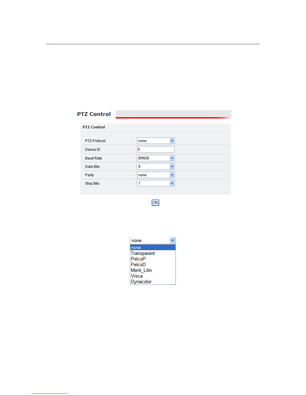
or define one by selecting “Other”. “Other” will present another field, “User
Assign”, where the desired time server can be defined.
After choosing a time server, click OK to apply the changes and update the time.
3.7 OSD (On-Screen Display)
The OSD and Camera Info. displays are independent.
The OSD settings relate to information (i.e. time) displayed along with the video
from the camera. In addition, the OSD section also controls the name associated
with the IP camera.
The OSD details are presented in the top left corner of the Live View.
By default the date and time are displayed.
The “Camera Name” is a user-defined name given to the camera. The camera
name must be a-z, A-Z, 0-9, and “-”; character spaces aren’t permitted.
The timestamp overlay of the video can be enabled/disabled via the “Enable
Timestamp Overlay” checkbox.
The camera name can also be enabled/disabled via the “Show camera name”
check box. The camera name will appear below the time & date.
Page 28

23
Page 29
24
4 THE SETTINGS P AGE – EXPERT
The following continues the description of the different configuration options within
the Settings page
4.1 PTZ Control (Pan, Tilt, Zoom)
Note: Only Video Servers, Box and Megapixel Cameras will have this
configuration option as of this firmware version.
To configure the PTZ Control configuration, please refer to the manufacturer’s
PTZ specifications. The PTZ Control settings will depend on these specifications.
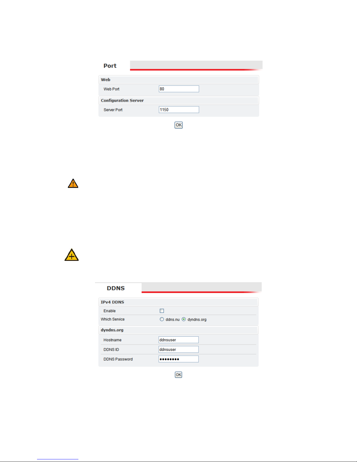
The following is a listing of the available PTZ Protocol settings.
Based on the manufacturer’s specifications, select the appropriate value for PTZ
Protocol, Device ID, Baud Rate, Data Bits, Parity and Stop Bits Device ID.
Page 30
25
4.2 Port
The “Web Port” is used to access the IP camera’s web interface. The default value
of Web Port is 80.
The “Configuration Port” is used for integrating applications with the IP camera.
The default port is 1150.
If the default port is changed (e.g. 8080) users must add the port number to
the IP address (10.1.21.5:8080).
4.3 DDNS (Dynamic DNS)
DDNS is used to map a dynamically assigned IP address (a device using DHCP)
with a hostname.
Certain network configuration will likely be required (i.e. mapping the IP
address recognized by the DDNS service to the IP camera) to implement DDNS.
Therefore, the network administrator will likely need to be consulted.
If the IP camera uses DHCP, a DDNS service can provide a hostname for use
with the IP camera.
Registration with one of the DDNS service providers (ddns.nu, dyndns.org) is
required for use of this feature.
Page 31
26
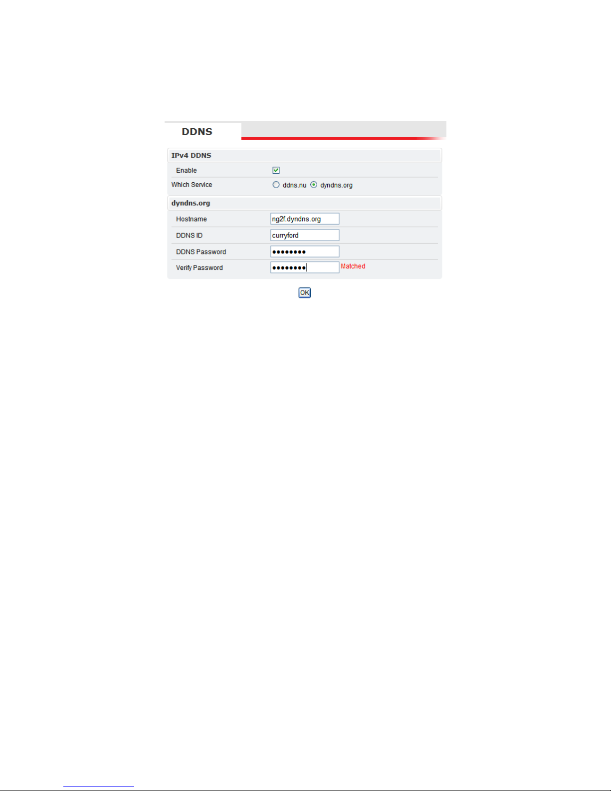
To enable DDNS, check the “Enable” box.
After registering with one of the DDNS services, enter the hostname, DDNS ID
and DDNS Password.
After configuring the DDNS and any networking modifications, the web
interface can be accessed via the hostname (i.e. http://[email protected]).
4.4 SMTP/FTP
The IP camera can be configured to send notifications via email. In addition, the
IP camera can also upload video and images using ftp.
Page 32
27
Remote SMTP Setup
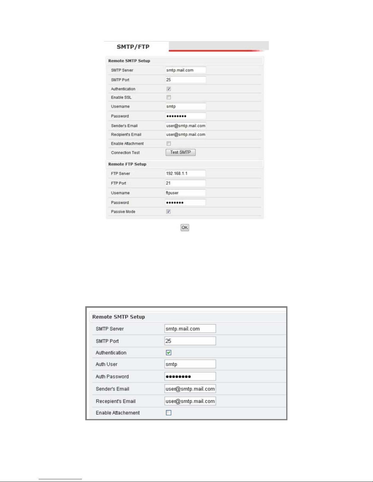
The SMTP settings allow the IP camera to send email notifications to a recipient’s
email account. These settings are used by various event triggers (i.e. Motion
Detection) defined in the in the “Event Rule” settings page.
The following parameters should be modified with the appropriate email settings.
Please verify this information with the email account administrator.
Page 33
28
After entering the appropriate email account settings, click OK at the bottom of
the screen to apply the changes. Next the email configuration needs to be tested.
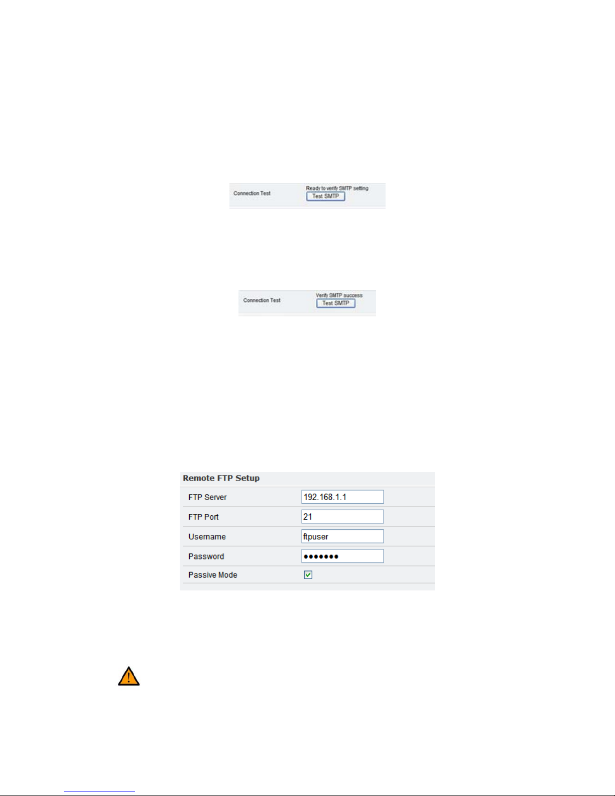
The “Connection Test” requires two steps.
1. In the “Connection Test” field, click Test SMTP.
If an error is encountered, then review the email settings, make the necessary
changes, and try the Test SMTP again until the “Ready to verify SMTP
setting” is displayed.
2. After receiving the status “Ready to verify SMTP setting”, verify the email
settings work with the SMTP server by clicking “Test SMTP” again.
If an error is encountered, then review the email settings, make the necessary
changes, and try the Test SMTP again until the “Verify SMTP success”
message is displayed.
No test email will be sent during the above configuration. Upon receiving “Verify
SMTP success”, email notification should be properly configured and ready for
use.
Click OK to apply changes.
Remote FTP Setup
Enter the address of the FTP server, port number, user name, and password.
Passive Mode may be required if the IP camera is accessing an FTP server outside
of a firewall.
Click OK to apply changes.
4.5 Trigger Setup
For proper operation, ensure the mini DIN cable has been properly
connected to digital I/O and RS-485 devices.
Page 34
29
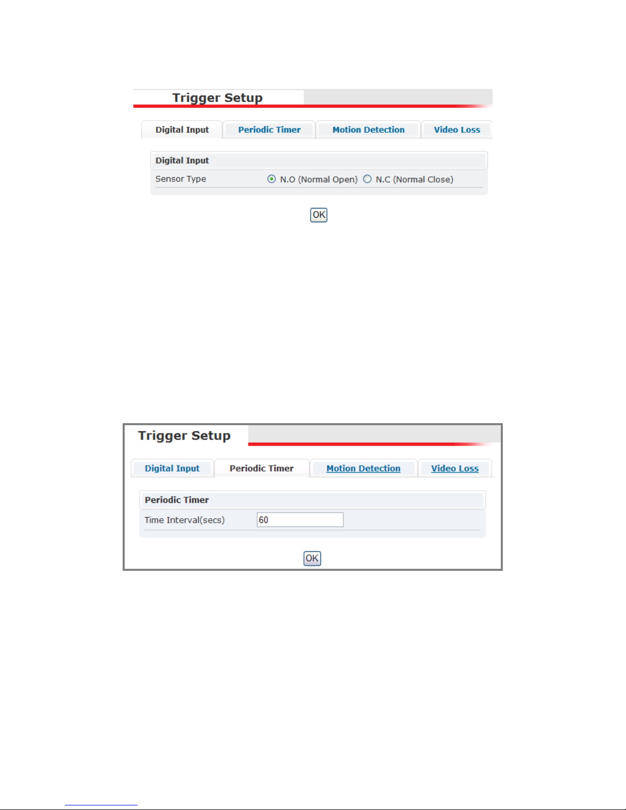
Three different events can be triggered.
Digital Input
There are two selectable options: Normal Open (N.O.) and Normal Close (N.C.)
N.O. represents the circuit should remain open; consequently, closing the
circuit represents the trigger.
N.C. represents the circuit should remain closed; consequently, opening the
circuit represents the trigger.
Choose the proper option depending on the input type; press OK to save the
setting.
Periodic Timer
The Periodic Timer will automatically trigger an event based on the time interval.
Set the appropriate value in seconds, and click OK to apply the changes.
Motion Detection
The “Motion Detection” trigger will trigger an event upon detecting motion in a
specified area of viewing.
Detection Setting
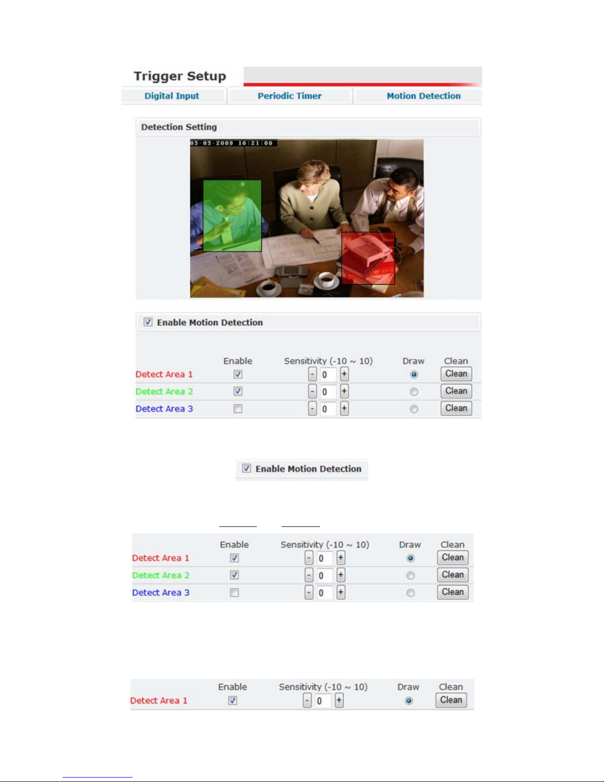
Below is the “Detection Setting” section of the “Motion Detection” settings page.
Page 35
30
The first step to enable motion detection is to check the “Enable Motion
Detection” option.
Below the “Enable Motion Detection” check box are detection area settings.
While “Enable Motion Detection” may be enabled, no events will be triggered if
no detection areas are defined and enabled.
The example above has two areas enabled (area 1 and 2). In the area displaying
the camera view, motion detection areas 1 and 2 are defined by shaded areas.
If an area is disabled, the defined area will remain, but will be grayed out.
The “Draw” and “Clean” functions are also available in the Detect Area settings.
Page 36
31
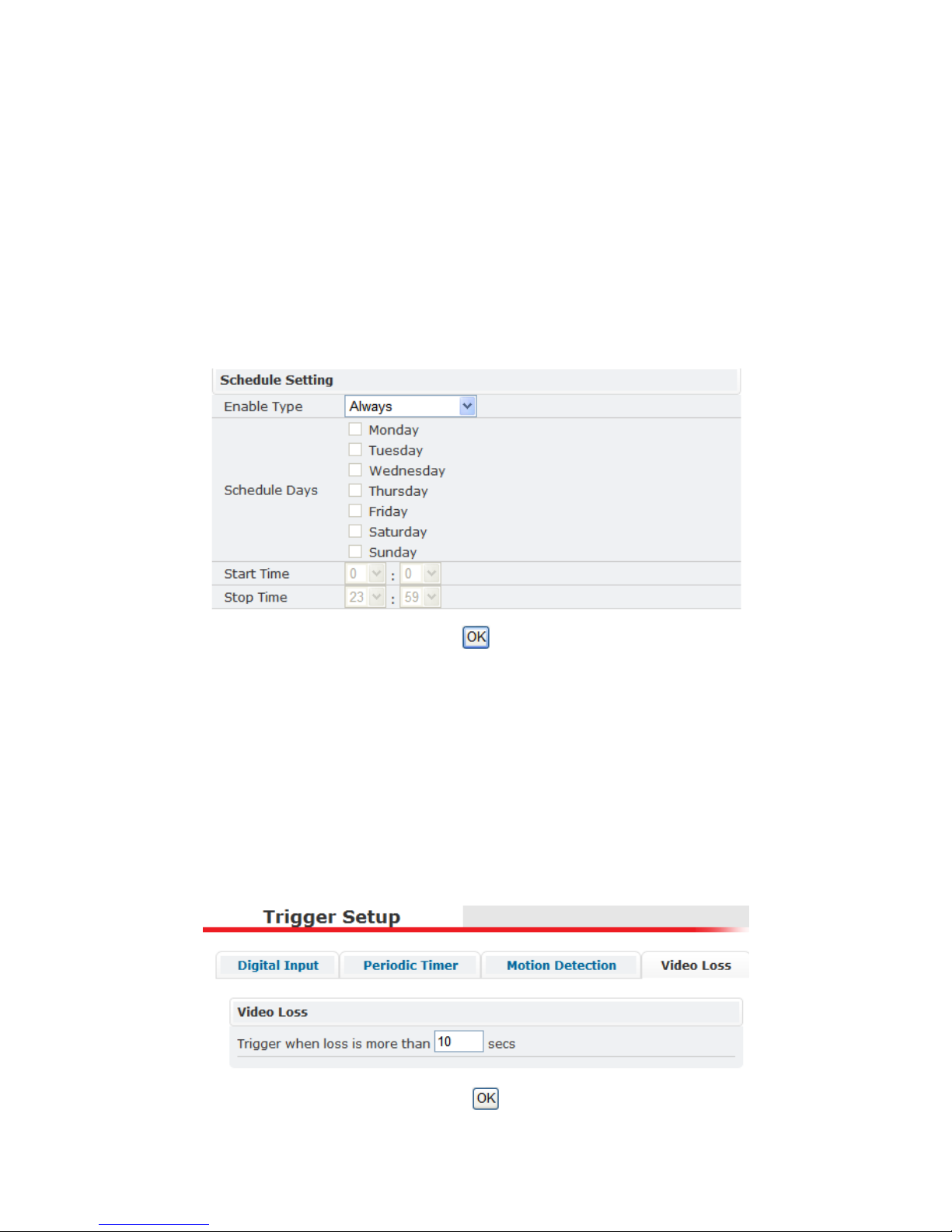
The “Draw” option defines which area (1, 2 or 3) can be defined in the viewing
portion at the top of the page. Using the mouse, the user clicks the left mouse
button, holds and drags to define an area.
The Clean button removes the corresponding detection area.
“Sensitivity” defines the sensitivity of the motion detection sensor for triggering
an event. Sensitivity values range from -10 (the least) to +10 (the most).
Schedule Setting
Along with the area detection settings, the “Schedule Setting” portion of the
settings page allows scheduling when the IP camera monitors for motion
detection.
“Enable Type” provides two options: “Always” and “Schedule”. Choose
“Always” if the IP camera should continuously perform motion detection.
“Schedule” allows configuring the IP camera to selectively determine when
motion detection should occur. Selecting “Schedule” will allow choosing a
start/stop time along with specific days to perform motion detection monitoring.
Click OK at the bottom of the page to apply any changes.
Video Loss
Note: Video Loss will only be found in video servers.
Page 37
32
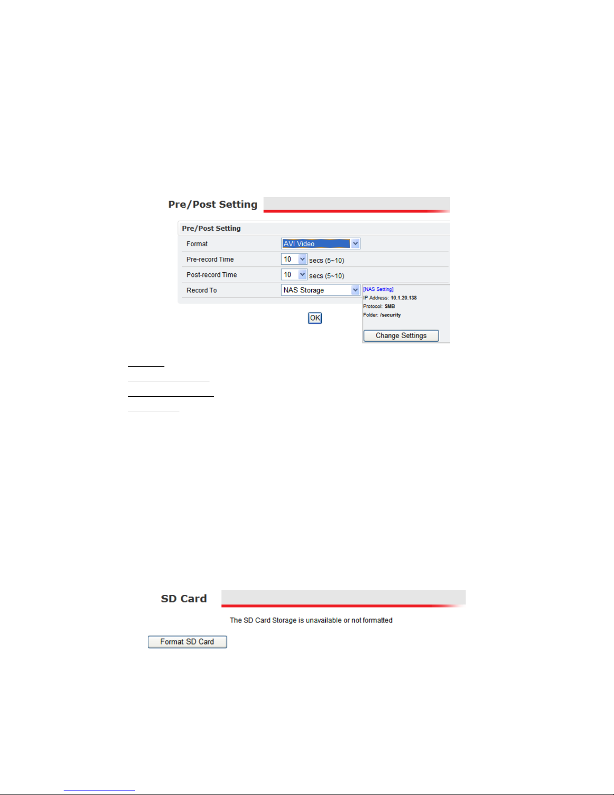
The Video Loss trigger will generate an event if video from the analog camera is
lost for a certain period of time. The default value is 10 seconds.
After setting a value, click OK to apply the setting.
4.6 Pre/Post Setting
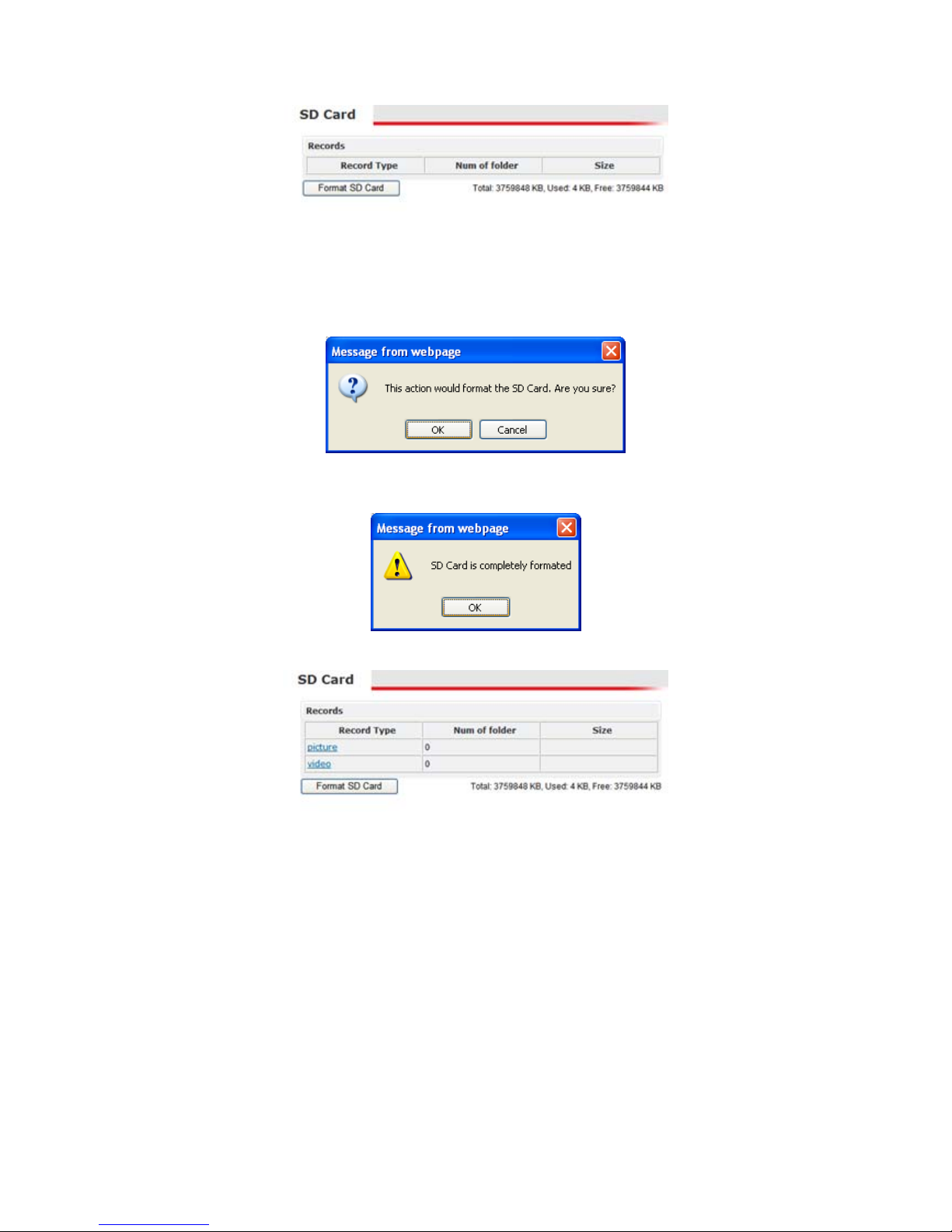
These settings configure the stream format type, duration of pre/post buffer
video, and storage method when a trigger handler is set to “Record”.
Format: options include “AVI” (for video file) and “JPEG” (for picture file).
Pre-record Time: duration of video prior to the event trigger to be recorded
Post-record Time: duration of video after the event trigger to be recorded
Record To: options include “FTP Upload” and “NAS Storage”.
Clicking Change Settings will redirect the browser to the corresponding
settings page (i.e. “NAS Setting” settings page).
4.7 SD Card
Note: Dome, Outdoor and Speed Dome models do not have SD Card
functionality as of this firmware version.
A high capacity SD memory card can be used for storing video and images.
After inserting the SD card, the camera will automatically detect the card. If the
card has never been used, then the card may be listed as unavailable or
unformatted.
If the camera has been previously used for other applications, then the SD card
information may resemble the following.
Page 38
33
Next format the SD card. This step is required to insure proper formatting and
creating the necessary directory structure.
Click Format SD Card. A confirmation dialogue will be displayed.
Click OK to format the SD card. After the card has been formatted, a notification
will be displayed.
The SD card is now ready for use.
4.8 NAS Setting (Network Attached Storage)
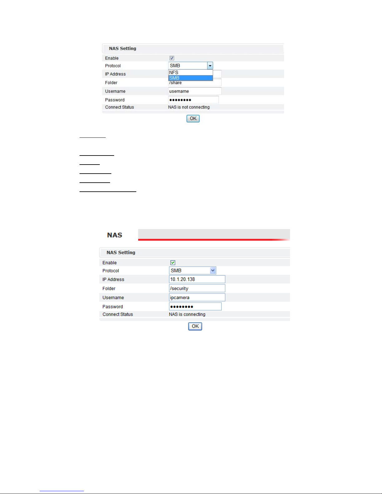
The NAS settings define the network storage parameters. To implement NAS,
check “Enable”.
Page 39
34
Protocol: defining the protocol for file sharing; the two options are SMB
(Server Message Block) and NFS (Network File System)
IP Address: the IP address of the where the network storage resides
Folder: the directory which the IP camera will access for file storage
Username: username for establishing NAS connectivity
Password: corresponding password
Connection Status: displays the status of the NAS connection; “NAS is not
connecting” or “NAS is connecting”
After configuring and clicking OK, check the “Connection Status”.
The following illustrates a successful NAS connection.
4.9 Account
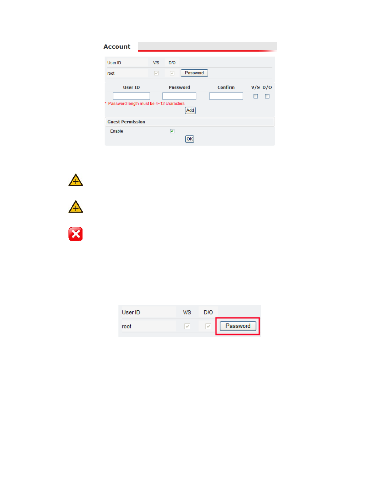
The Account settings page allows the administrator to manage user and guest
accounts.
Page 40
35
The Administrator Account
It is recommended changing the administrator (root) password after the
initial network configuration.
The ID of administrator can not be changed or deleted; only the password is
changeable.
Forgetting the root password will require resetting the IP camera’s default
factory settings to regain root access. See “Reset Default Factory Settings” for
more information.
Administrator has the authority to view and control system settings.
To change the administrator (root) password, click Password for the root User ID.
The administrator account, root, cannot be changed or deleted. Only the
password is changeable.
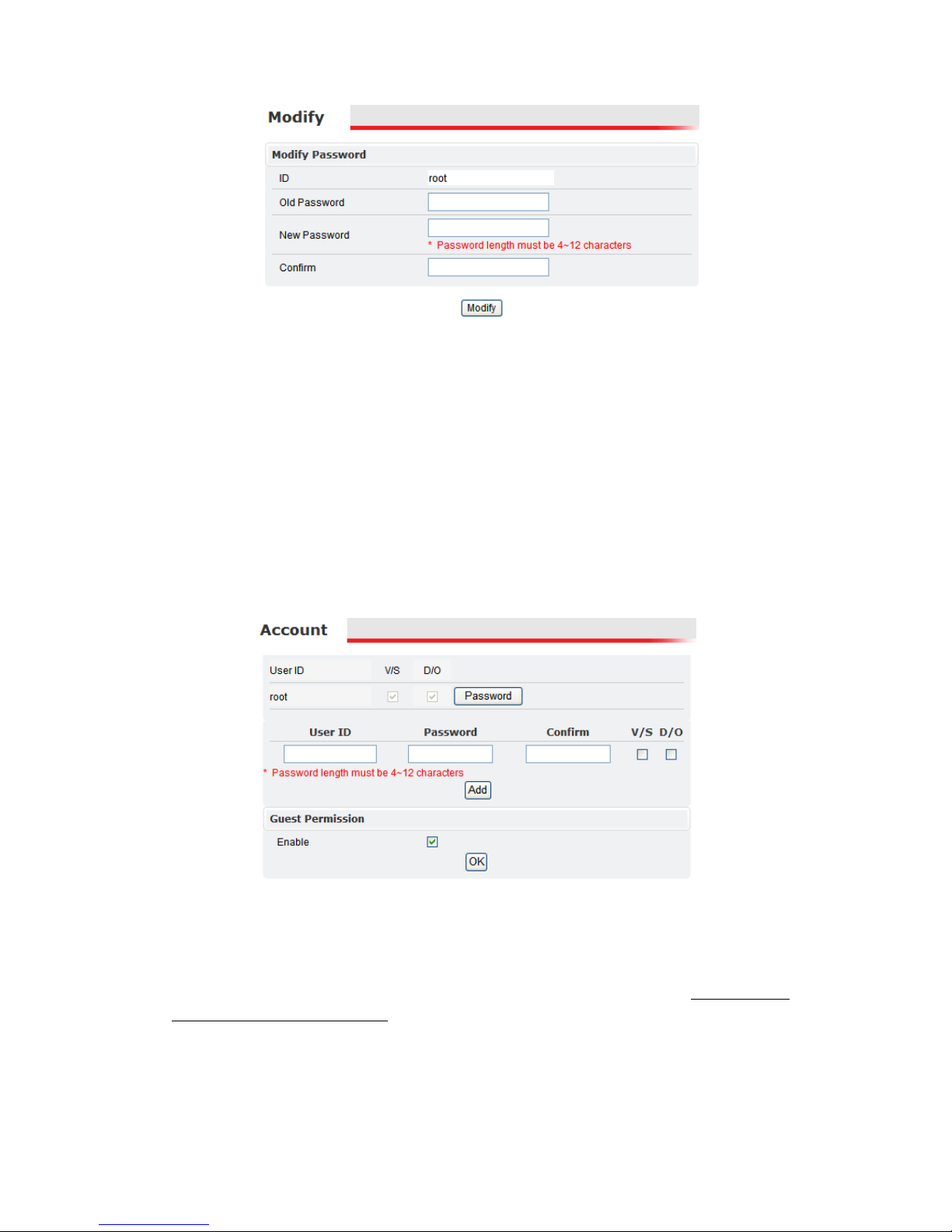
A new page will be displayed for changing the root password. Enter the
appropriate information and click Modify.
Page 41
36
The administrator account, root, cannot be changed or deleted. Only the
password is changeable.
User Accounts
The administrator can also create new user accounts (up to five additional users).
User accounts can be created by entering the “User ID” and password, then
clicking Add.
Users can be assigned different combinations of authorities including video
settings (V/S) and digital out (D/O).
There are limits to the length of user’s name and password. If the length exceeds
the limit, a dialog box will appear for notification.
Guest Permission
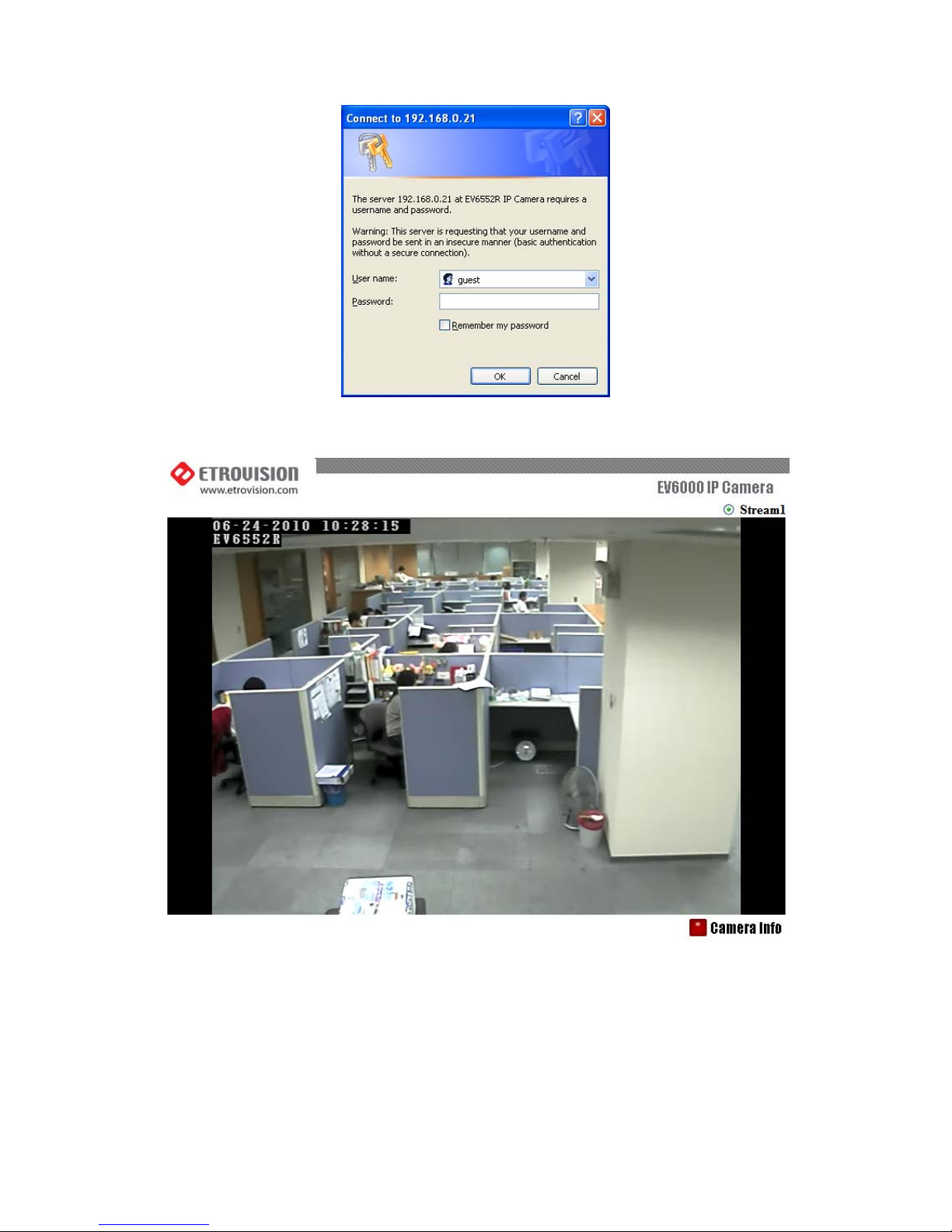
“Guest Permission” corresponds to a special account, guest.
Enabling this account allows browser access via the guest account. This account
doesn’t require a password.
Page 42
37
The “guest” account is limited to viewing Stream1, Stream2 (if enabled) and
“Camera Info”.
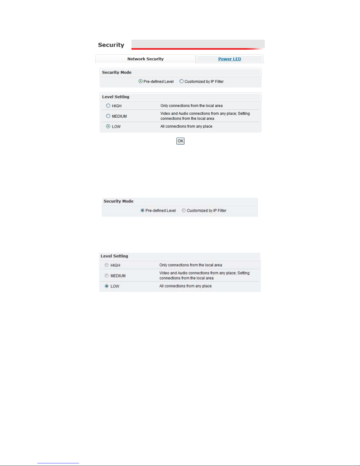
4.10 Security
The Security settings allow restricting network access to the web interface and
video/audio output. In addition, the Power LED on the back of the IP camera can
be disabled for security purposes.
Page 43
38
Network Security
The Network Security settings allow restricting access to the IP camera by
network addresses. There are two modes which are available: Pre-defined Level,
Customized by IP Filter.
Pre-defined Level
The default setting is “Pre-defined Level” and “LOW” which allows connections
from anywhere.
The “MEDIUM” and “HIGH” settings present restrictions based on if the
connections are local to the IP camera or outside of the local area network.
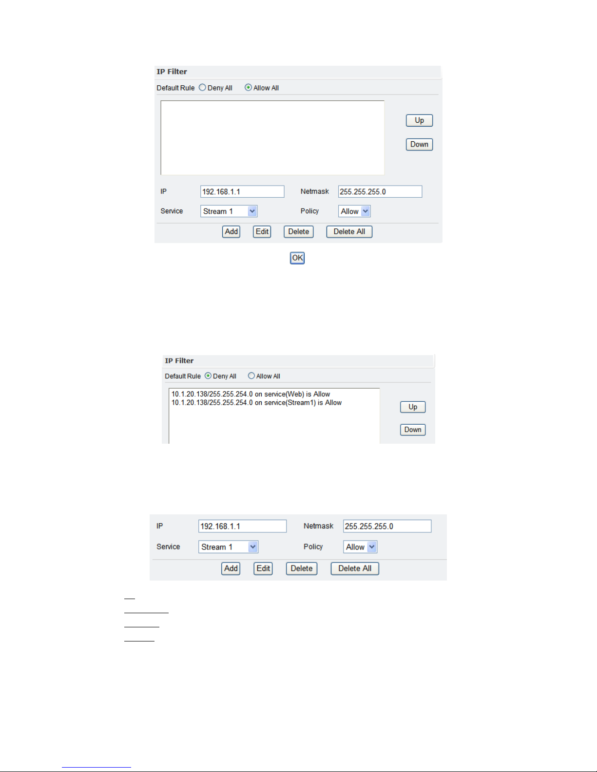
Customized by IP Filter
The Customized by IP Filter allows greater flexibility in defining access to the IP
camera.
Page 44
39
The “Default Rule” defines if the emphasis is on exclusion or inclusion. “Deny
All” will deny access to all except for those who are granted access. Conversely,
“Allow All” will allow access to all except for those who are excluded.
In the pane below “Default Rule”, rules will be defined which allow/exclude
access to subnets and/or specific IP addresses.
The rules are evaluated in order starting from the top and moving down. The Up
and Down buttons can move rules up and down. The order of the rules is
important, and will be illustrated in an example in the next section.
Near the bottom are the settings for defining rules.
IP
: an IP address; this can represent a subnet
Netmask: the netmask of the IP address
Service: Stream 1, Stream 2, Web (port), Configuration (port)
Policy: Allow or Deny
Add adds the rule to the rule pane above.
Edit will allow edits to an existing rule. First highlight the rule in the rule pane,
edit the information in the rule settings, and click Edit to apply the changes.
Page 45
40
Delete will delete a specific rule, while Delete All will delete all the existing rules.
Click OK to apply any changes.
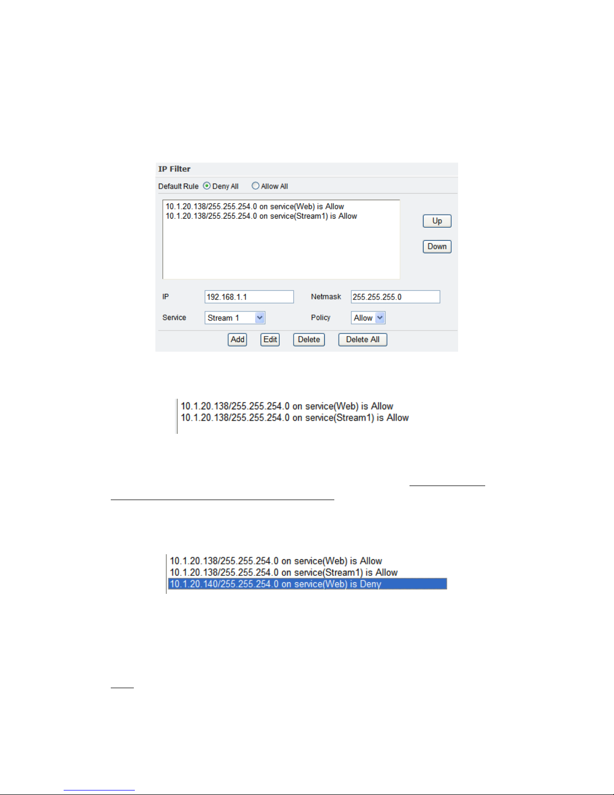
Customized by IP Filter Example
Below is a screenshot which will be used for explaining the Customized IP Filter
functionality.
Firstly, the “Default Rule” is “Deny All”. So, all access by default is denied.
However, two rules have been defined in the rule pane.
Here we are allowing access to the IP 10.1.20.138/255.255.240.0 for the Web and
Stream1 service.
While it appears we are only allowing access to 10.1.20.138, we are actually
allowing access for those on the same subnet. Despite access to Web and Stream1,
10.1.20.138 cannot access Stream2. The “Deny All” requires that this be granted
for access.
Next we add the following rule.
This rule is denying Web access to 10.1.20.140. Although, “Deny All” is currently
in effect, 10.1.20.140 is on the same subnet. It has access via 10.1.20.138 having
access.
Despite adding the rule to deny 10.1.20.140, 10.1.20.140 still can access the web
interface because of the order of evaluation. The rule denying 10.1.20.140 comes
after the rule allowing access to 10.1.20.138.
Therefore, the 10.1.20.140 must be moved to precede the rule allowing access to
10.1.20.138. We use the Up button to move the rule.
Page 46
41
After applying the changes, 10.1.20.140 cannot access the web interface. However,
others on the same subnet as 10.1.20.138 can access the web interface.
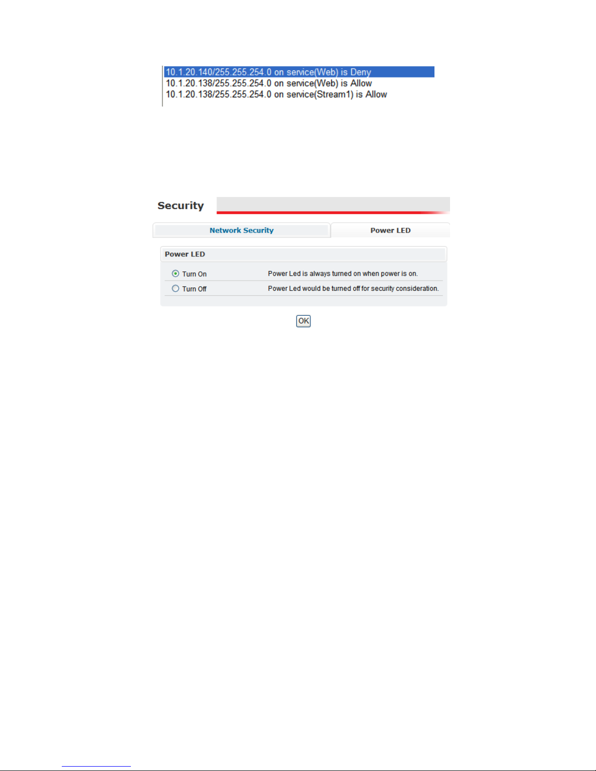
Power LED
The Power LED on the back of the IP camera can be enabled and disabled.
If the “Turn Off” option is chosen, the light will remain off unless the camera is
rebooting. During the reboot the camera light will blink; the light will remain
unlit after finishing the reboot.
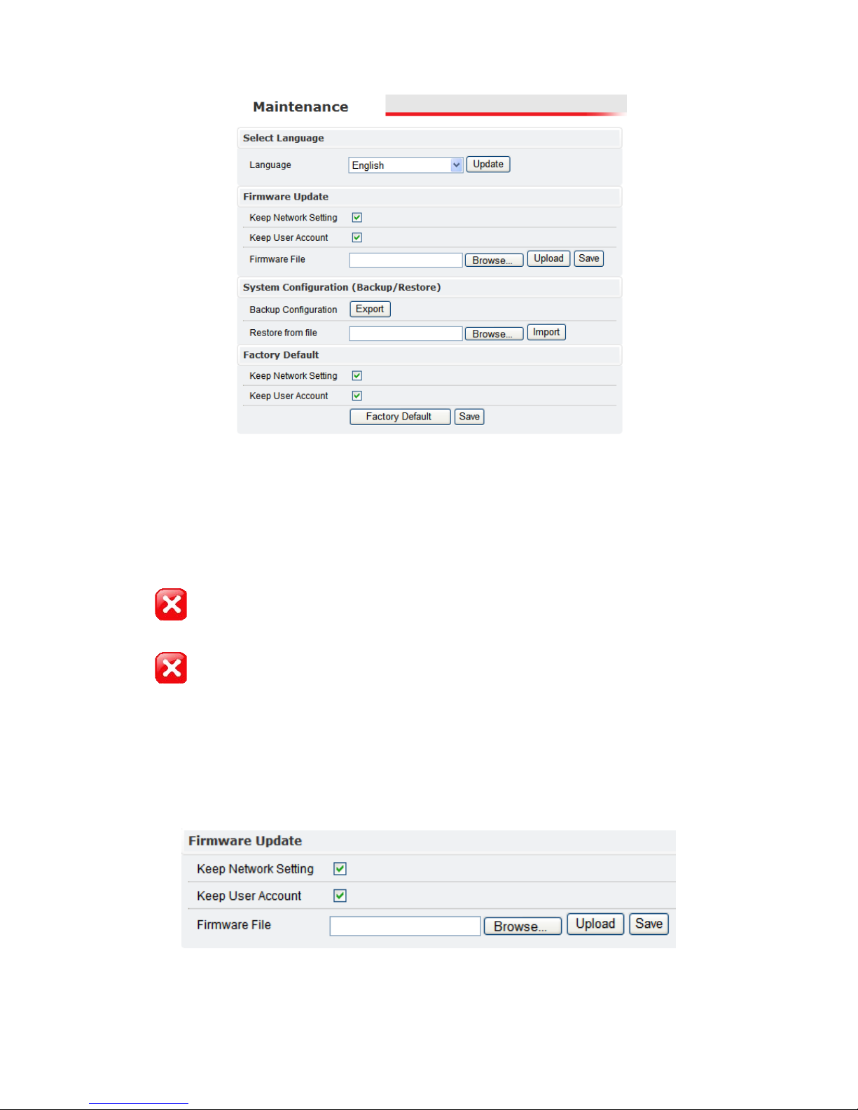
4.11 Maintenance
The Maintenance section allows for configuring language settings, firmware
updates, IP camera configuration backup/restore operations, and restoring
factory default settings.
Page 47
42
Language
The following language options are available: English, Traditional Chinese,
Simplified Chinese, Japanese, French and Polish. The default setting is English.
Firmware Update
The power supply must be steady as upgrading the firmware. The power
failure during the upgrade process results in serious damage to the machine.
Configuration settings will be lost after applying a new firmware version.
Backup the IP camera’s configuration prior to the firmware update (see “System
Configuration (Backup/Restore)” in the next section).
Firmware can be downloaded from Etrovision’s website, www.etrovision.com.
Prior to updating firmware, check “Keep Network Setting” and “Keep User
Account” if the network/account settings should be preserved during the
firmware update. Click Save to make the change permanent.
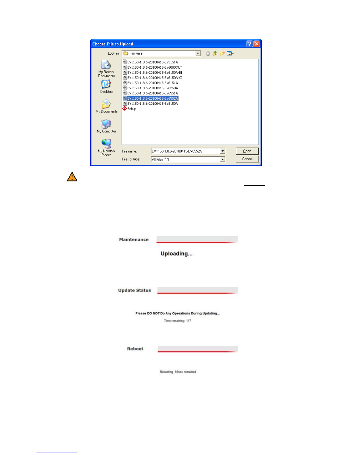
After downloading the appropriate firmware version, click Browse to select the
firmware file.
Page 48
43
Caution: No confirmation will be provided after clicking Upload; the
firmware update will automatically proceed. Please verify everything before
proceeding.
After selecting the firmware file, click Upload.
A sequence of messages will follow. No IP camera operations should be
performed during this time.
Next…
Lastly…
After the reboot is complete, the camera will have the factory default network
settings. These will need to be modified.
Page 49
44
After logging into the web interface, check the “Firmware Version” field in the
“Status” Settings page to confirm the firmware has been successfully updated.
System Configuration (Backup / Restore)
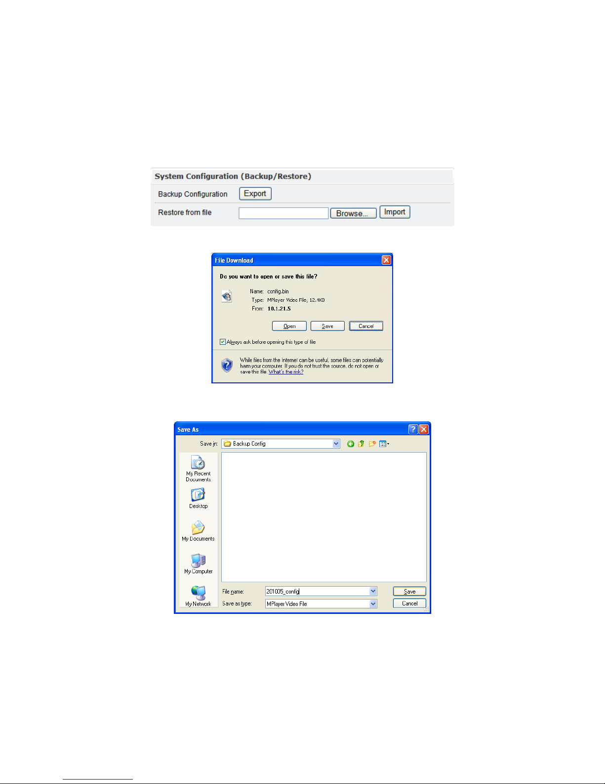
The current configuration settings can be backed up to a file on the PC which can
be restored if necessary.
Clicking Export will open an additional IE window and the following prompt.
Click Save which will bring up an explorer window where the user can choose
the location and name for the backup configuration file.
Click Save to save the file, additional prompts should be self-explanatory.
After saving the file, a blank IE browser window will remain open. This can be
closed.
To restore a previous configuration from a backup file, click the “Restore from
file” Browse button. Select the backed up configuration file.
Page 50
45
Caution: No confirmation will be provided after clicking Import; the
firmware update will automatically proceed. Please verify everything before
proceeding.
To continue with restoring the system configuration, click Import. The file will be
uploaded and a reboot will ensue.
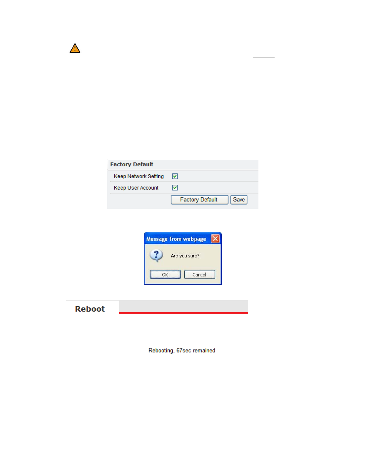
Factory Default
This function will restore the factory default settings.
Prior to restoring the factory default settings, check “Keep Network Setting” and
“Keep User Account” if the network/account settings should be preserved
during this process. Click Save to make the change permanent.
Click Factory Default to restore the factory default settings. A confirmation
dialogue window will be displayed. Click OK to proceed or Cancel to abort.
The system will reboot following confirmation; wait for the countdown timer.
After rebooting the system will refresh the screen.
Page 51
46
5 REBOOT
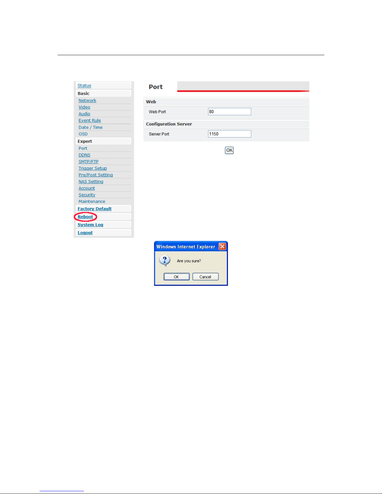
Pressing Reboot will display a confirmation dialog box.
Press OK to continue with the reboot; the reboot countdown timer will start running.
After finishing, a prompt for refreshing the page will appear. Confirming will log the
user back into the Live View page.
Page 52
47
6 SYSTEM LOG
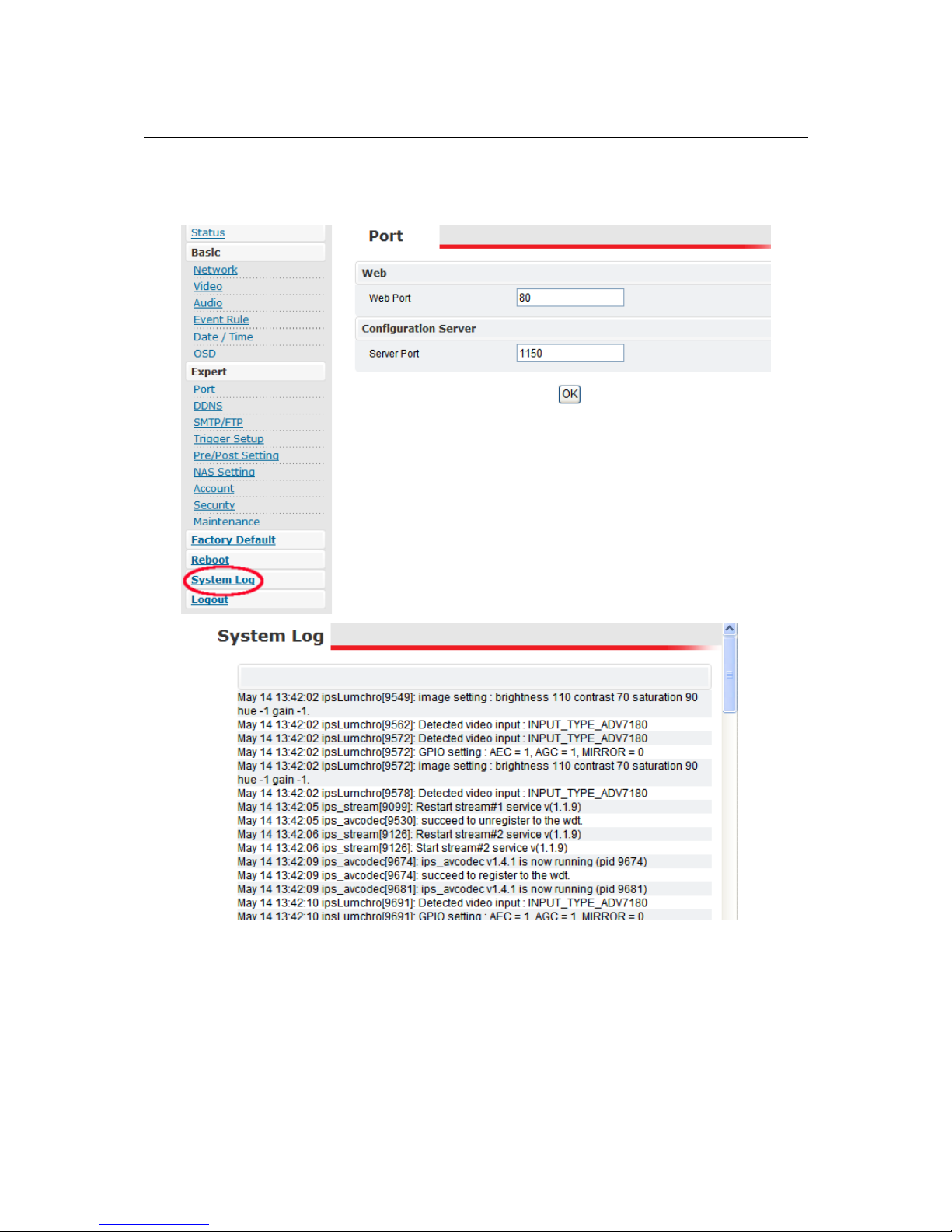
The System Log is a log containing information which may be needed for
troubleshooting purposes.
The log entries have a timestamp which start from the oldest and go down the page
to the most recent.
Most of the entries are only informational and will likely only be used in the event of
investigating a problem with Etrovision Technical Support.
Page 53

48
7 LOGOUT
Logout will log the user out of the IP camera web interface. This will require the user
to input user/password credentials when logging back into the web interface.
Pressing Logout will exit the Settings page.
Clicking Logout will display a confirmation dialog box. Select Yes to close the IE
browser window.
Page 54
49
8 WIRELESS CONNECTIVITY
With an Etrovision supported wireless dongle, the IP camera can be used on a
wireless network.
There are two methods for enabling and configuring wireless connectivity: the web
interface, the EtroLink™ Configuration USB port.
The methods described below will assume configuration of a new IP camera using
the factory settings.
8.1 Web Interface Configuration
First connect the LAN cable to the camera.
Insert the wireless dongle into the WiFi port.
Plug the power adapter and wait for the camera to boot.
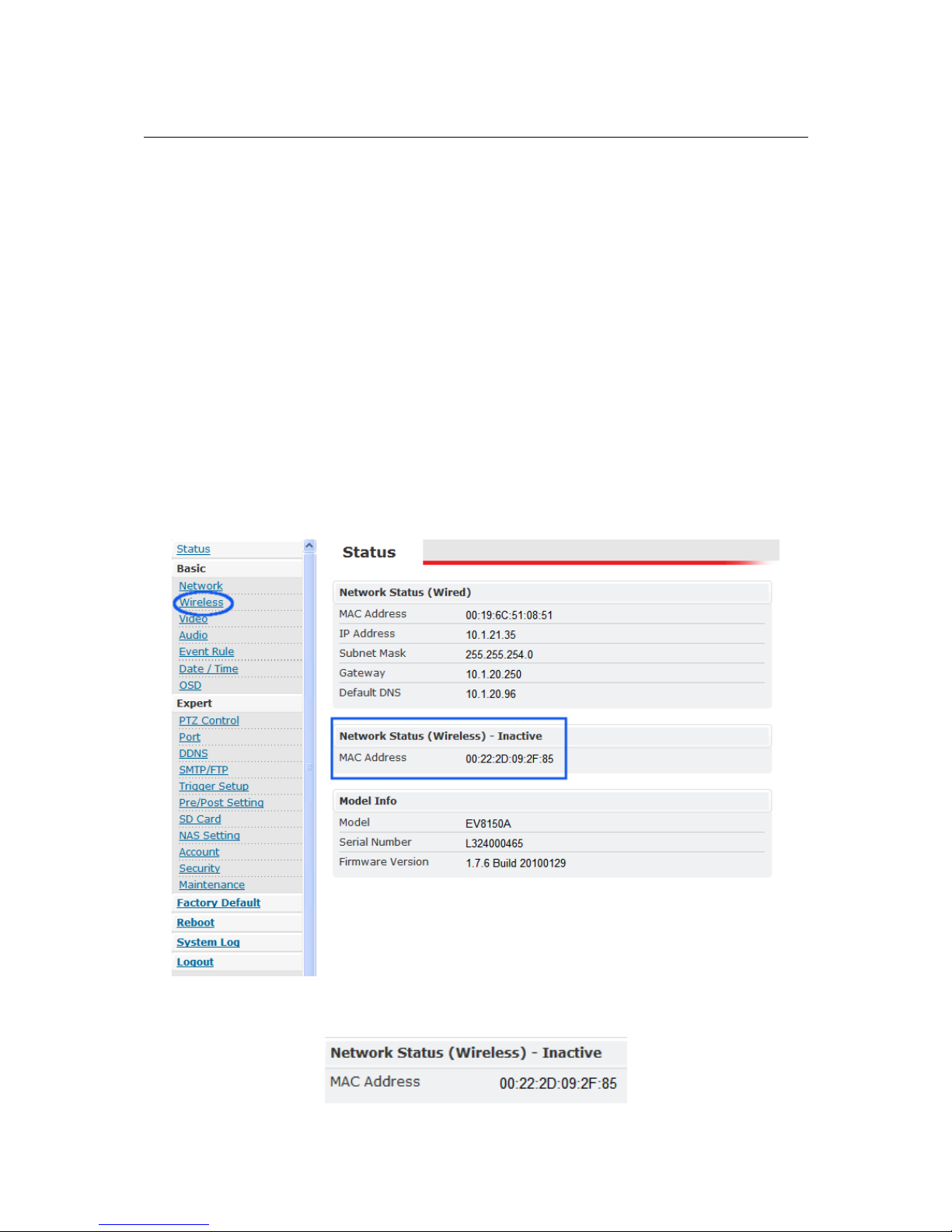
Log into the web interface (i.e. http://192.168.1.2). Navigate to the “Status” page
in the Settings page.
In addition to the LAN network settings, the “Status” page will also display
details related to the wireless dongle.
Page 55
50
One important consideration is that the LAN network interface and the wireless
network interface use different MAC addresses. This is an important distinction
when searching for the IP address of the camera when using DHCP.
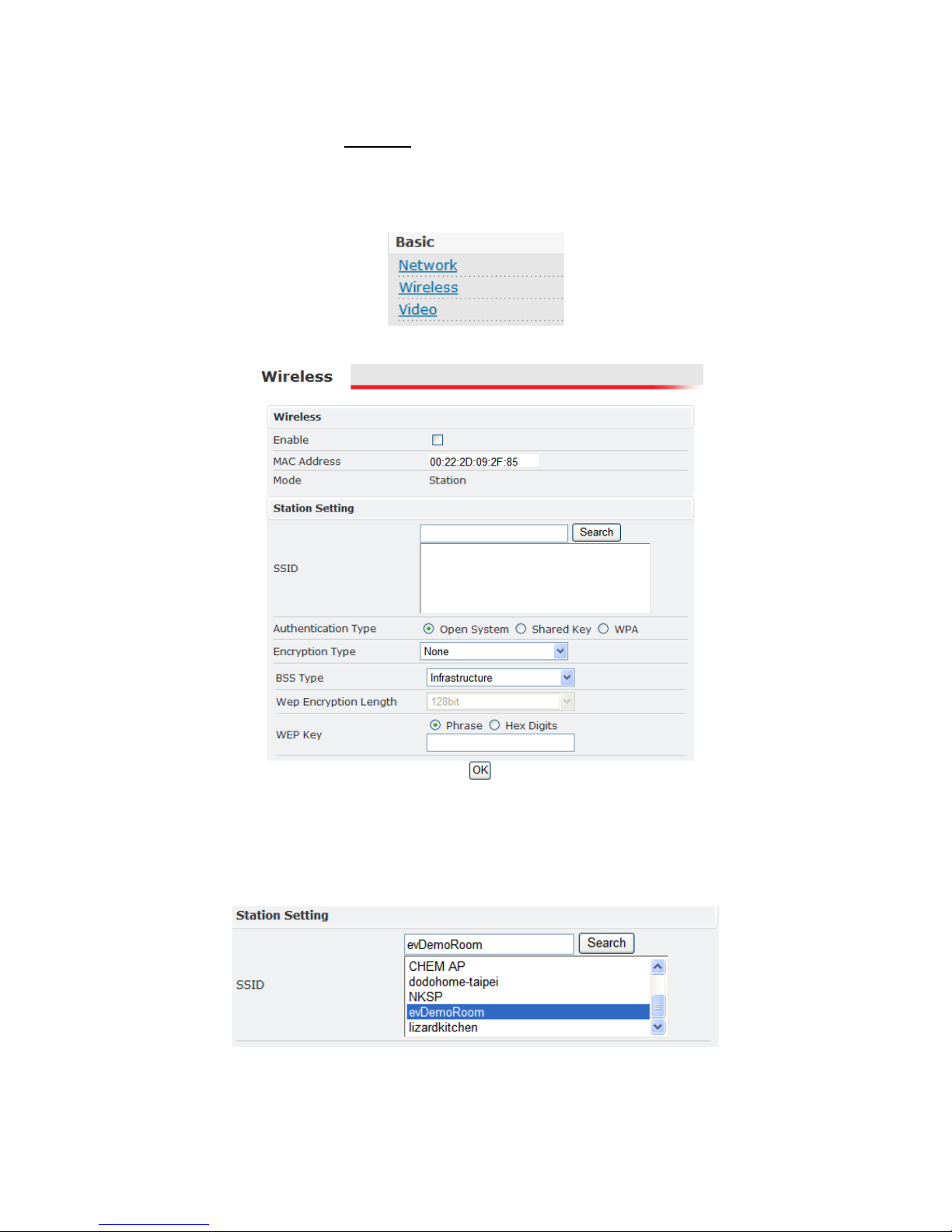
There is also a new entry, “Wireless”, on the Settings menu items located on the
left side of the page.
Select “Wireless” to display the wireless configuration settings.
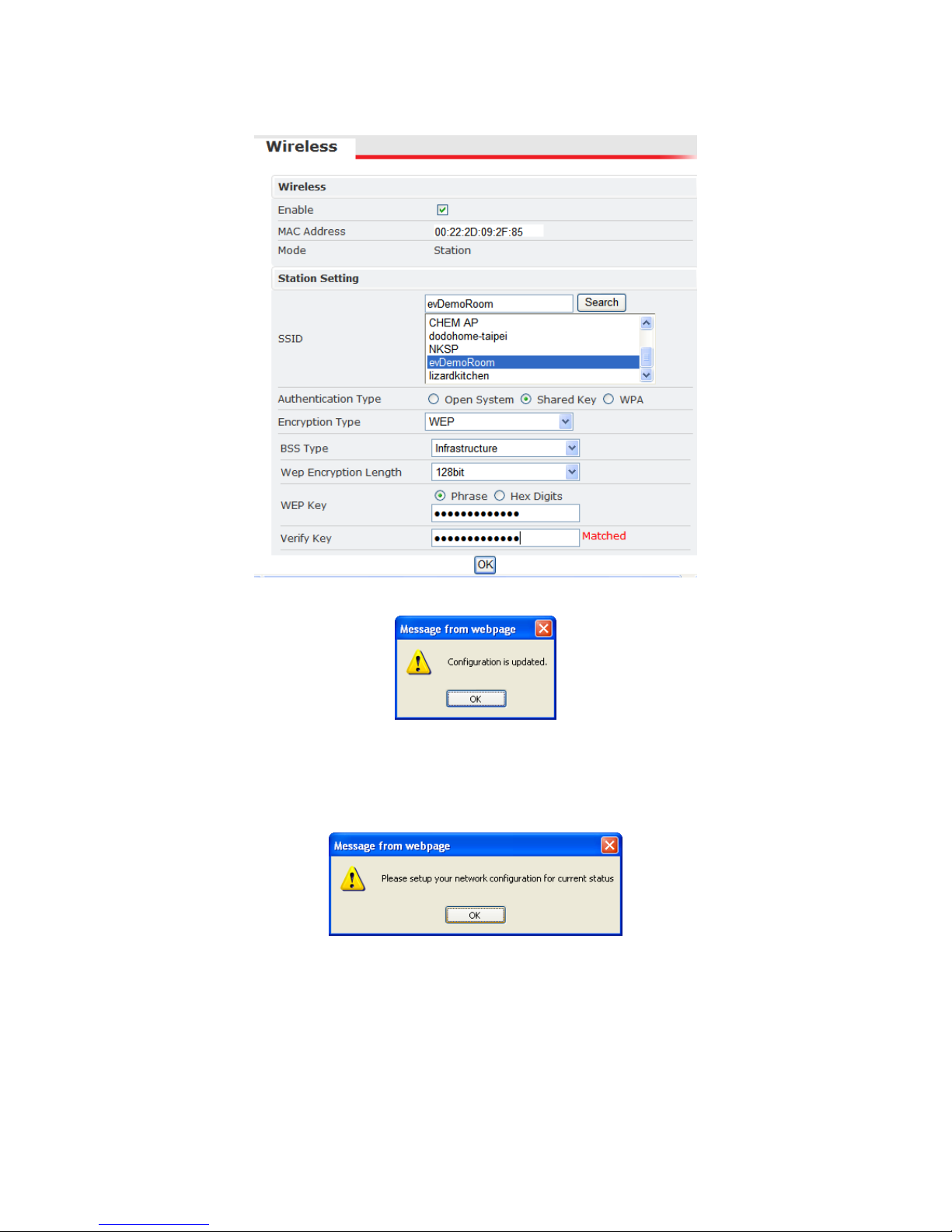
Before enabling the wireless network interface, check if the desired wireless
network is available.
Click Search in the “Station Setting” section. After a moment, a list of available
wireless networks should be listed.
Highlight the wireless network to connect to.
Check the “Enable” box to implement wireless connectivity.
Page 56
51
Enter all the relevant information for the specified SSID.
Click OK to apply the settings. A confirmation will follow; click OK.
Another confirmation will follow which is noting that the network configuration
needs to be updated. Following this dialogue, the network settings screen will be
displayed.
Click OK.
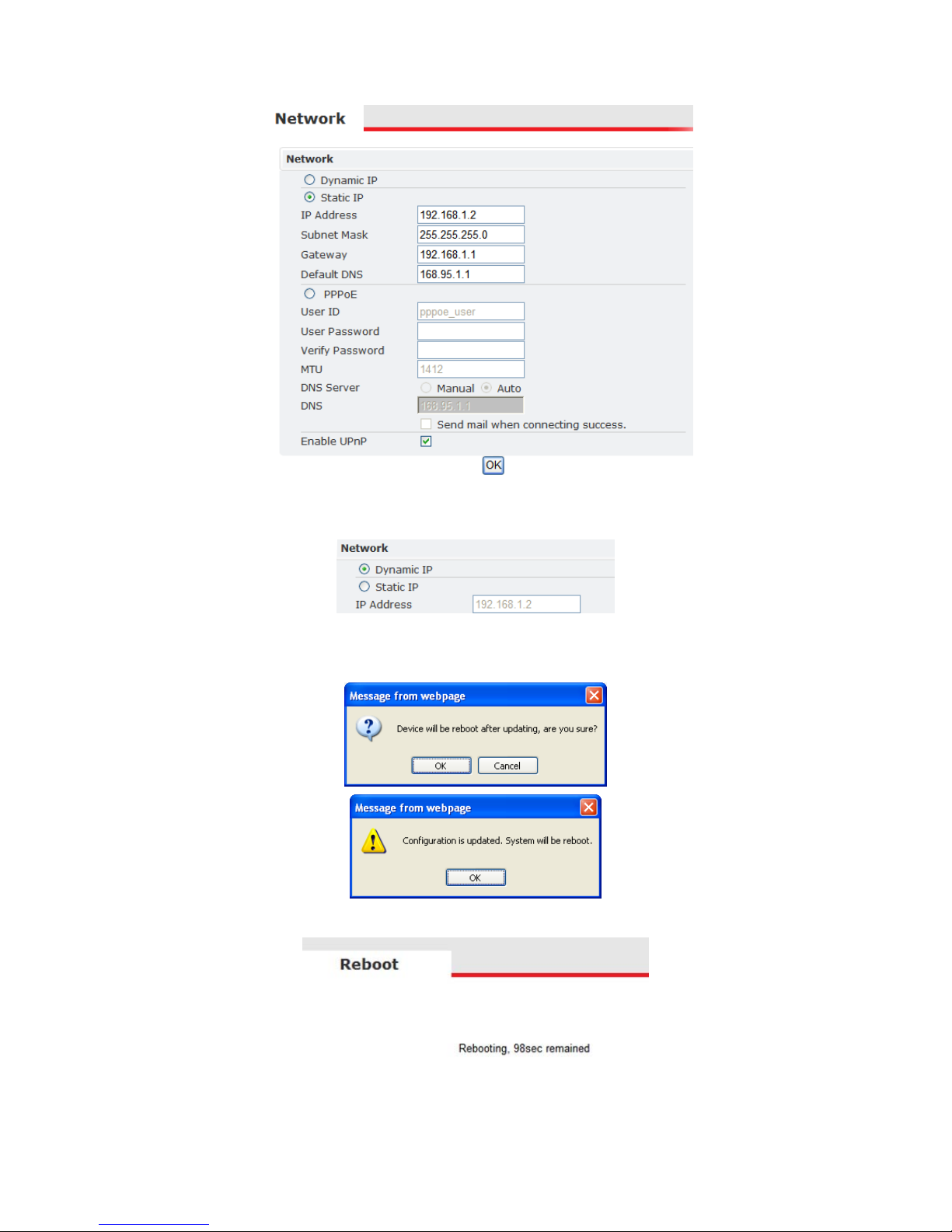
Now the Network configuration settings will be presented.
Page 57
52
Change the configuration settings to apply to the wireless network. For this
example, DHCP will be used.
Click OK to apply the changes.
Two confirmations will follow; click OK for both.
Next the reboot timer screen will be displayed.
Now the LAN cable can be unplugged.
Page 58
53
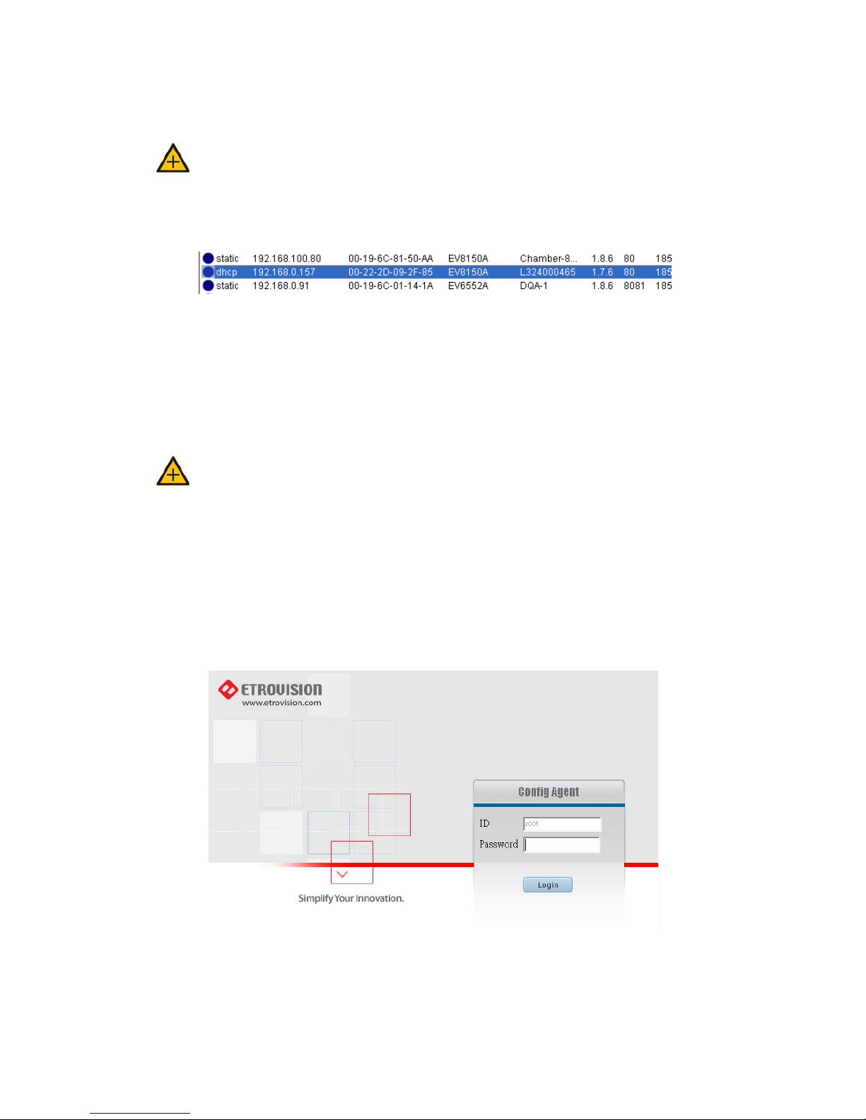
Since this example assumes DHCP is being used, use EtroScan™ to find the IP
address after the reboot.
Use the wireless dongle’s MAC address, not the MAC address for the LAN
interface.
Using the MAC address of the wireless dongle, the camera’s IP address is
identified.
This IP address can be used to access the IP camera’s web interface.
8.2 EtroLink™ USB Configuration Port
Unlike the web interface method of wireless configuration, the EtroLink™ Quick
Config utility doesn’t display the wireless network interface’s MAC address.
Refer to the label on the dongle or the packaging for the MAC address.
Use The MAC address can be obtained from the label on the dongle or the
packaging.
Unplug the power adapter and the LAN cable.
Insert the wireless dongle into the WiFi port located in the read of the camera
Connect the IP camera and the PC using the mini USB cable.
Once the PC has recognized the IP camera, select “Config Wizard” in the
program option list (or start it manually per instructions in the “EtroLink™
Configuration Port” section).
Assuming no changes have been made to the administrator account, enter “pass”
for the root password.
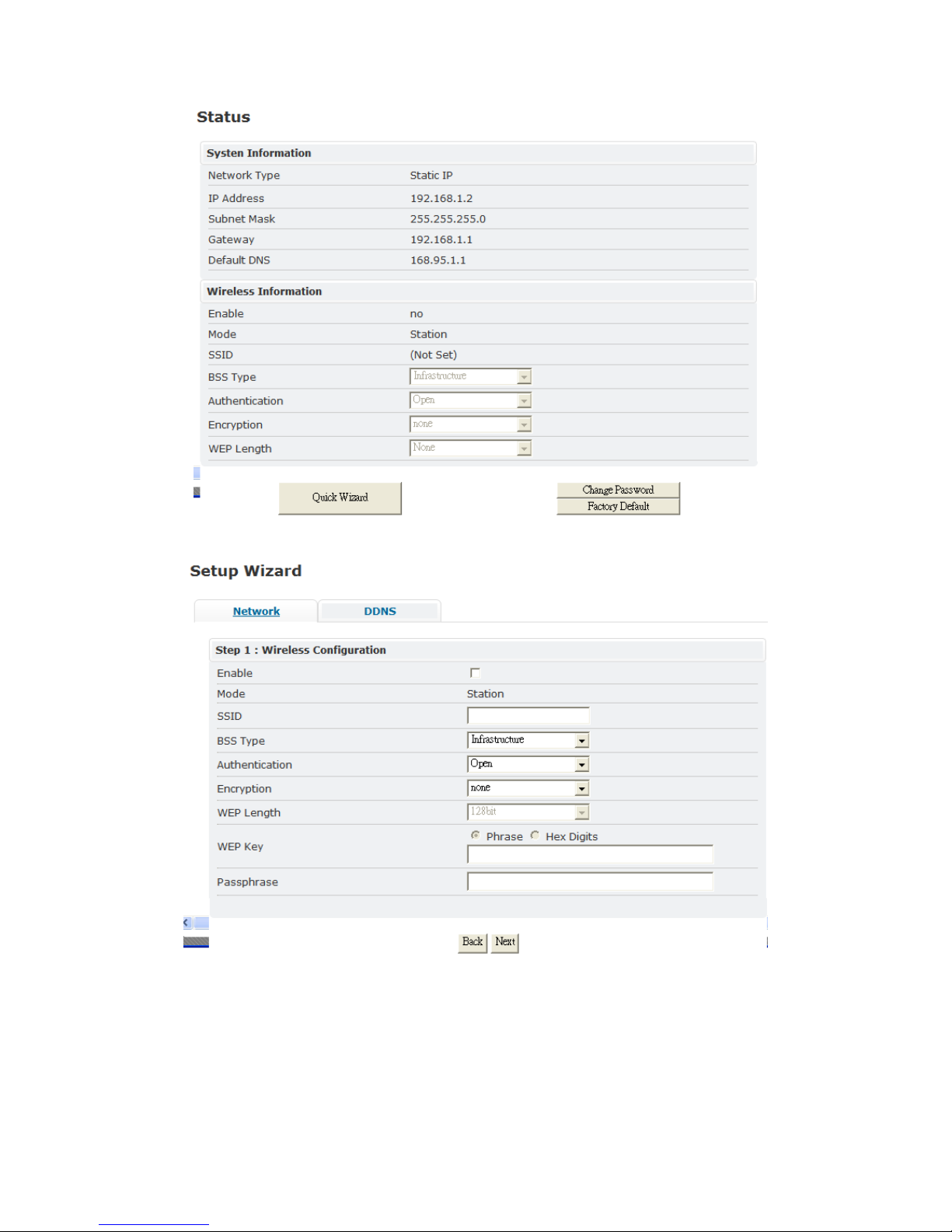
The “Status” screen will now have a “Wireless Information” section.
Page 59
54
Click Quick Wizard to continue.
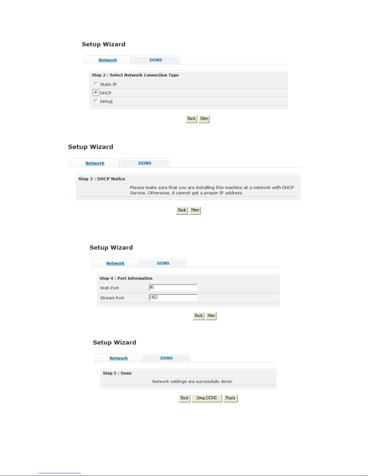
Check the “Enable” box, enter the information for a specific SSID, and click Next.
Choose the appropriate network connection type for the wireless network. DHCP
is used for this example.
Page 60
55
Click Next to continue.
Click Next to continue.
Change the ports if different from the default values.
Click Next to continue which will display a confirmation dialogue; click OK.
Click Finish to exit the Quick Config utility.
Page 61
56
Unplug the IP camera from the PC, and connect the power adapter to the IP
camera.
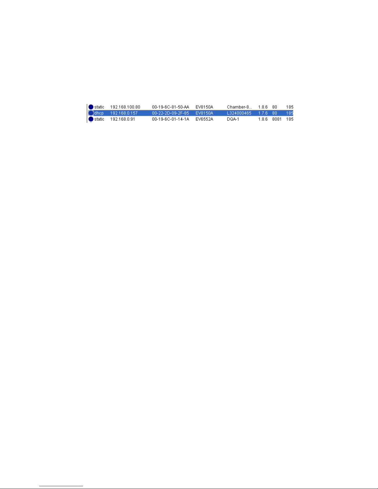
After the camera starts, EtroScan™ can be used to identify the IP address.
However, the EtroLink™ Quick Config doesn’t display the MAC address, so this
will need to be obtained from the wireless dongle or the packaging.
Using EtroScan™, the IP address can be found.
This IP address can be used to access the IP camera’s web interface.
Page 62
57
9 EV6156A COLOR SETTINGS
The EV6156A IP Camera uses a specific CCD board which provides additional
video functionality and controls. Therefore, the EV6156A has a special Color
Setting page which is independent of the web UI.
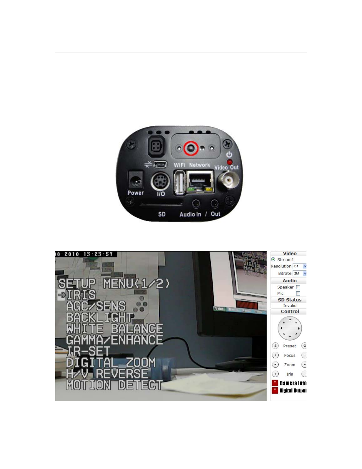
These functions and controls are accessed via a separate OSD interface. On the
rear of the camera is the OSD button highlighted in red below. It is also a toggle
button which can be pressed up, down, right, left.
To enter the Color Settings OSD menu, press and hold the OSD button for a few
seconds. The menu will appear in the Live View area.
To exit toggle left; the menu will also disappear if there is no user input for a
couple of minutes.
Page 63
58
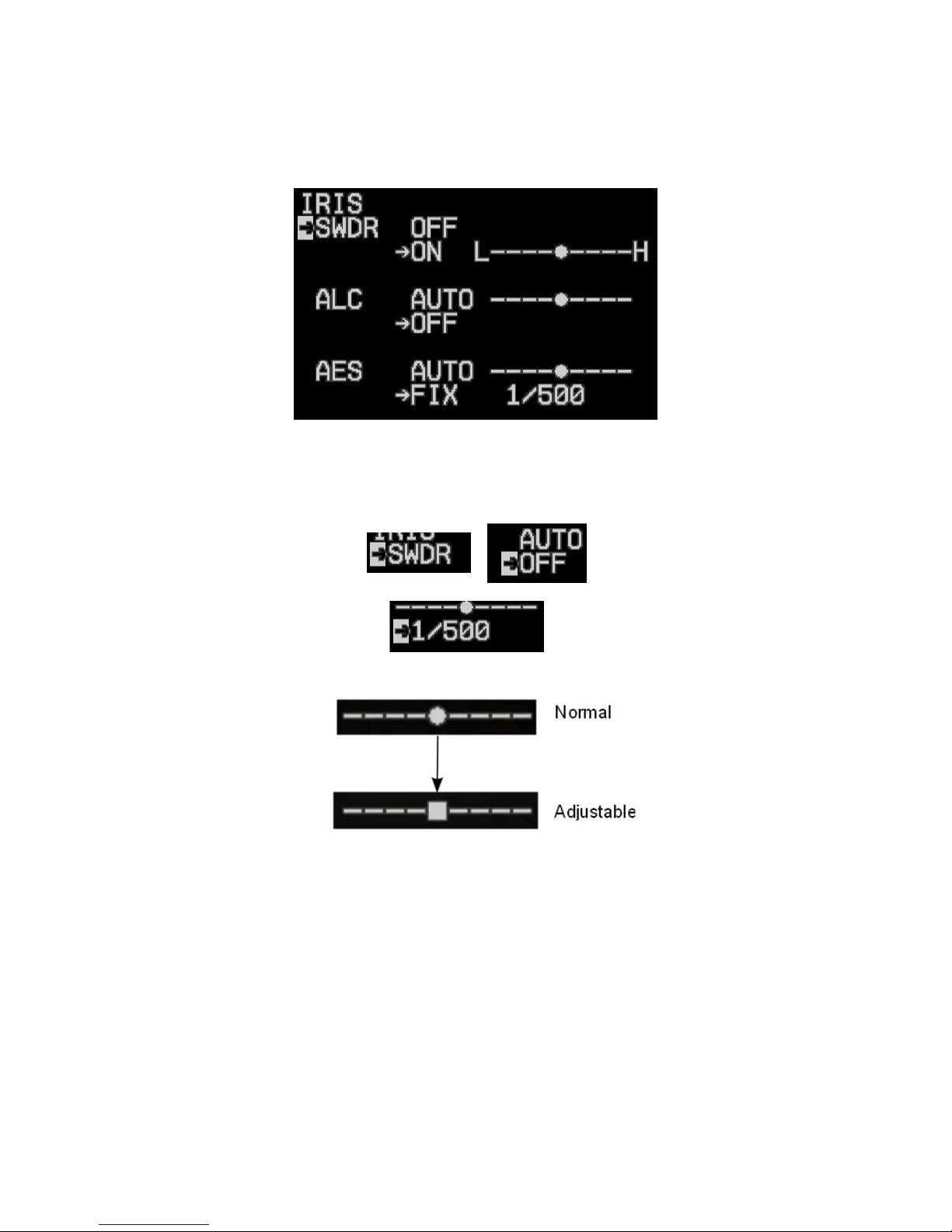
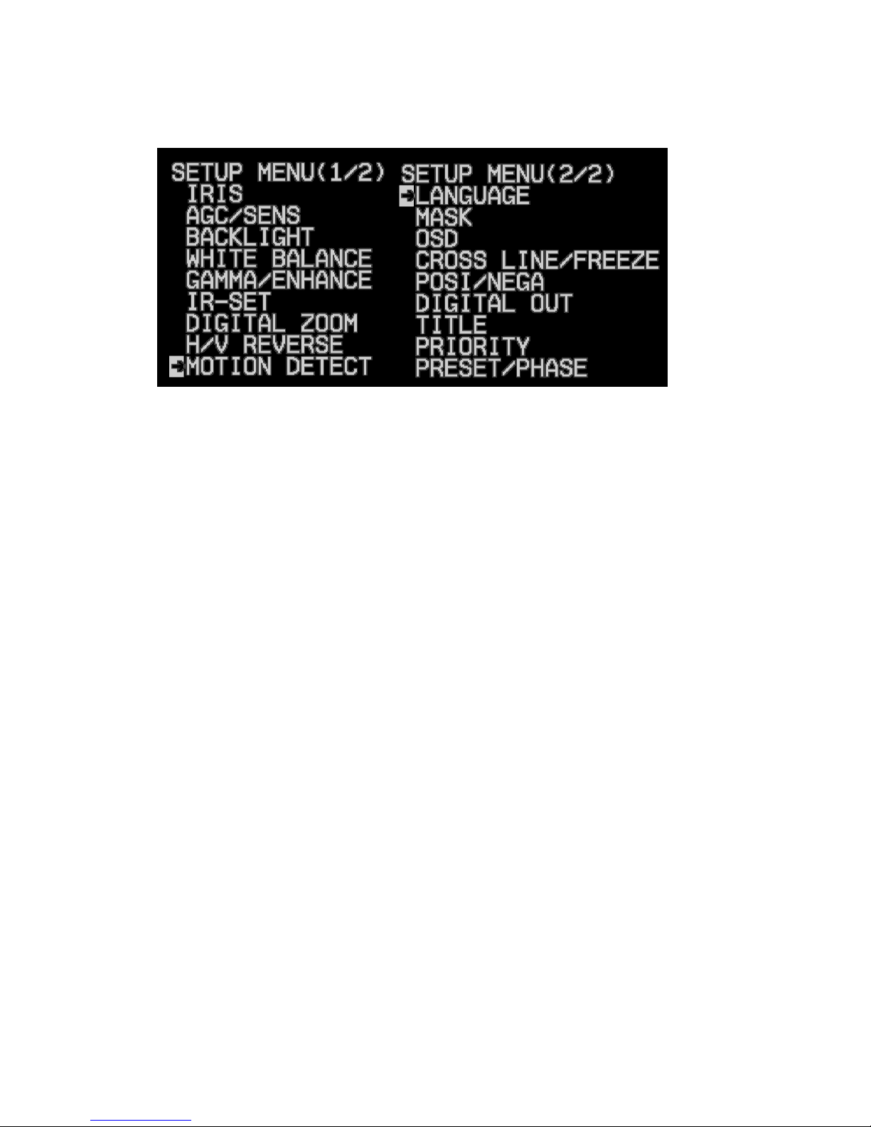
The Setup Menu has 2 pages; toggle the button up/down to move through the
options.
To access an option’s submenu (i.e. IRIS), press the button to enter the submenu.
In the sub menu, toggle the button up/down to move through options. Press the
button to go down a level. Note that the current option/level will be denoted
with a highlighted arrow or option.
Toggle left to go up a level; from the top level of a submenu, toggle left to return
to the main menu.
To make an adjustment (e.g. raise/lower a setting) or flip through configuration
settings, toggle up/down.
Page 64
59
9.1 Menu Options
IRIS
Controls the iris and shutter speed of the lens. It included 3 items SWDR (Super
Wide Dynamic Range), ALC (Auto Light Compensation), AES (Auto Electronic
Shutter).
「SWDR」:SWDR mode ON/OFF select, at ON mode can be adjust SWDR
level.
「ALC」:ALC is used to select AUTO or FIX. Adjust IRIS level
「AES」:AES is used to select electronic shutter be AUTO or FIX function, at
AUTO mode can be adjust AES level, at FIX mode can be selector shutter speed
at below,
[OFF],[1/100sec],[1/120sec],[1/180sec],[1/350sec],[1/500sec],
[1/750sec],[1/1000sec],[1/2000sec],[1/4000sec],[1/10000sec].
AGC/SENS
AGC (Auto Gain Control) and Sens-up.
「AGC」:To adjust auto gain control select [AUTO] or [FIX]
「SENS」:Makes sensor more sensitive in low lux conditions; select [OFF] or
[AUTO] which also provides a level of adjustment
BACKLIGHT
BLC (Back Light Compensation)
「BLC」:ON / OFF selector. Selector [ON] has sub-item [AREA].
「AREA」: 48 BLC zones can be set separately. Toggle up/down to move the
dark cursor; press the button to enable/disable BLC for a specific block.
Page 65

60
According to the mask area (BLC zone), the sensor will determine the iris level
and shutter speed.
WHITE BALANCE
Controls white balance and the gain rate for RED & BLUE.
「COLOR」:Selector OFF is monochrome image,ON is normal color image,
AUTO is at low light AGC up, display image will be auto change to monochrome
image.
「WB」:AWB (Auto White balance) and ATW (Auto Trace White balance)
The AWB and ATW offset level can be adjusted.
「GAIN」:The gain rate of R-Y and B-Y can be adjusted separately.
GAMMA/ENHANCE
Gamma correction adjusts the overall luminance.
「GAMMA」:TYPE-1 gamma is 0.45; TYPE-2 gamma is 1.0
「ENHANCE」:Adjustment level
IR-SET
IR-CUT Filter operation
「OFF」:Disables ICR control
「AUTO」: Enables ICR control which is dictated by AGC-LEVEL.
「TIME」is the delay time: 1, 5, 10 ,20 ,30 ,40 ,50 , 60 sec.
「EXT」: Select this mode ICR control is by external signal decide output.
DIGITAL ZOOM
4x digital zoom
「OFF」:Select this mode digital zoom is off.
「ON」:4x digital zoom; POSITION X & Y position the magnification viewing
area
H/V REVERSE
Flips the image horizontally or vertically
「H-REVERSE」:Horizontal Reverse (Mirror) ON/OFF
「V-REVERSE」:Vertical Reverse (Up-side down) ON/OFF
Page 66

61
MOTION DETECT
Motion detection should be managed via the web interface or an NVR.
Please do not use the OSD interface for motion detection settings.
A basic form of motion detection is available. When motion is detected,
“MOTION” will be visible in the display. The OSD “MOTION” option also needs
to be set to ON to enable motion detection.
「OFF」:Motion Detection Off
「ON」:Motion Detection On
「AREA」:Toggle up and down to move the selection cursor. To
enable/disable motion detection for a specific block, press the button; a motion
detection enabled block will be highlighted light gray, while a clear block is
disabled.
「TIME」:The motion detection video time.
「SENS」:Motion detection sensitivity.
LANGUAGE
OSD menu language
「ENGLISH」: English mode
「JAPANESE」: Japanese mode
MASK
Masks a viewing area
「NO」: 1-4; represents a mask area
「OFF」:Disables a specific mask area
「ON」:Enables a mask area can be use
H-START & H-END represent horizontal defined area
V-START & V-END represent vertical defined area
OSD
These functions should remain disabled. This functionality should be
implemented using the web UI.
OSD motion detection and zoom
「MOTION」: Motion detection; Off/On.
Page 67

62
「ZOOM MAG」:Zoom times display; Off/On.
CROSS LINE/FREEZE
Cross line displays a cross line splitting the screen into quadrants. Freeze freezes
the video.
「LINE」:Cross line display
「FREEZE」:Image freeze
POSI/NEGA
Normal or negative image
「OFF」: Negative image viewing off
「ON」:Negative image viewing on
DIGITAL OUT
These settings shouldn’t be modified. Changes can result in a loss of video.
Adjusts the digital output format
「FORMAT」: 422 (YUV4.2.2) or 656 (ITU656); the value should be 656
「CLOCK」:DO clock active; positive or negative
「DATA」:DO pixel format; UYVY, VYUY, YUYV, YVYU
TITLE
A title or text can be placed in the video display.
「→」: Text entry area
Press button to place cursor at first space of title line. Toggle up/down to move
forward/backward.
Press button again to choose a character; toggle up/down to move cursor to
desired character.
「POSITION」: Place the text in the upper or lower part of the screen; off
disables the option
PRIORITY
This functionality should be set to OSD and remain unchanged.
Used to control priority between OSD menu or hardware VR & switch
「VR PRIORITY」:Iris lever control priority; OSD menu or hardware VR
Page 68

63
「SWITCH PRIORITY」:OSD menu or hardware switch
PRESET/PHASE
This relates to PTZ functionality which should not be managed using the
OSD interface. Please use the web interface to manage PTZ.
PRESET on/off and lock on/off & phase adjustment.
「PRESET」:Select preset ON/OFF mode of CCD sensor.
「ID」:RS-485 connection ID number
「PHASE」:Select line lock ON/OFF mode, ON mode can be adjust line lock
phase.
Page 69

64
10 ADDITIONAL INFORMATION
For more information please reference the IP camera/video server Installation Guide.
This manual is available on the product CD, or it can be downloaded from the
Etrovision website, www.etrovision.com.
In addition, the latest firmware releases and other product documentation are
available in the Download area.
Page 70

65
11 GLOSSARY
A
ActiveX
ActiveX is Microsoft software component technology, mainly used by Microsoft
Windows. This protocol facilitates the sharing of information between different
components in a networked environment.
AGC (Automatic Gain Control)
This function automatically adjusts the amount of increase depending on the
strength of the incoming signal.
AI (Auto Iris)
A very useful approach to control the strength of lights. This function automatically
detects the light level of image to determine the movement of the device. Basically
the auto iris opens or closes the lens iris as the light turns dimmer or brighter.
Alarm Input
This facility allows various forms of external alarms, such as door contact, reed
switched, Passive Infra-red detector, or vibration sensors, to be connected to the
security camera. As receiving an alarm signal, the specific camera will be switch on.
Analog Signal
Analog signals are continuous rather than discrete or pulsed, varying in voltage,
frequency, or phase of quantities.
Angle of view
Also known as viewing angle, this refers to the available angular range within a
certain image size. The smaller the focal length, the wider the angle of view is.
Aspect Ratio
Aspect Ratio refers to the ratio of width to height in images. 4:3 is a common aspect
ration used in television screens and computer monitors.
Automatic White Balance
This function automatically adjusts the color to achieve the “color balance”. This
function will give the reference of “true white” to show the camera what the color
white looks like.
B
Bandwidth
Measured in bps, this unit refers to the transmission capacity of telecommunications
links.
BLC (Back Light Compensation)
Page 71

66
This function automatically adds more details to darker areas of an image when
bright lights, for example shining from behind, obscuring.
BNC connector
This is a type of RF connectors that interconnect two coaxial cables. BNC connector is
usually used to with CCTV components such as network cards or video connections.
bps (Bits Per Second)
This unit is used to measure the speed of data moving between sources. For
example, 1Mbps is roughly equal to 128 KBps.
Byte
This is a unit of digital information. A unit of eight bits is known as a Byte.
Bitrate
The bit rate (in kbit/s or Mbit/s) is defined as the number of bits/time unit.
C
CCD (Charge Coupled Device)
CCD is one type of computer chips. It is designed for the movement of electrical
charge. Basically CCD converts the light energy that enters a camera into an
electrical charge, which is then converted into an electronic image. There are two
types of CCD: frame transfer and interline transfer.
CCTV (Closed Circuit Television)
CCTV represents for the use of video cameras to transmit the signal. In CCTV
system, all devices are linked mostly and directly via cables. The system is different
from broadcast television where the signal is openly transmitted. CCTV system is
widely used in video surveillance, involving analog cameras and recorders.
CIF (Common Intermediate Format)
This format is used to standardize the horizontal and vertical signals of the image.
The default frame resolution of 352x288 for DVR systems is known as the CIF.
CMOS
CMOS is the abbreviation of Complementary Metal-Oxide Semiconductors. This
device is widely used in static RAM, microprocessors, microcontrollers, and other
digital logic circuits.
CS-Mount
CS-Mount is one of specific types of camera, as well as its corresponding lens
mount. CS-mount has a flange focal distance of 12.52 millimeters.
Coaxial Cable
Coaxial cable is also called coax and used to transmit radio frequency (RF) signals. It
is the kind of copper cable with a central conductor that’s surrounded by a shield
Page 72

67
sharing its same axis. It is often used by cable TV companies, telephone companies,
and business and corporation Ethernet and other types of local area network.
CODEC
CODEC means the technology used to compress and decompress data stream or
signal. It converts analogue input into digital, and then converts it back to
analogue. CODECS can be either software applications or hardware components, or
both. CODEC does coding and decoding, containing no compression.
CGI
CGI is the abbreviation of Common Gateway Interface. It is a standard protocol for
interfacing external applications with information servers, such as HTTP or Web
servers. A CGI program can be written in any language that allows it to be executed
on the system, such as: C/C++, PERL, Visual Basic etc.
Compression
It is a process of encoding information while reducing the size of digital signal.
D
D1
D1 is the so-called full resolution for TV specification. D1 refers to the following
resolution: 720x486 (NTSC) or 720x576 (PAL). It was one of Sony’s first digitized
videotape formats.
dB (Decibel)
This unit is used to measure sound level and also widely used in electronics, signals
and communication. A decibel is a logarithmic unit to describe a ratio and measure
the loudness, power, or strength of a signal.
DHCP
DHCP is the abbreviation of Dynamic Host Configuration Protocol. It is a computer
networking protocol used by devices (DHCP clients) to obtain configuration
information for operation in an Internet Protocol network. So that it can
communicate with other host computers. These addresses are usually dynamic, so a
connection cannot be obtained (or maintained) over the open Internet. Use of both
static IP addresses and dynamic DNS helps establish a consistent connection.
DNS
DNS is the abbreviation of Domain Name Service/System/Server. This is an Internet
service that translates domain names into IP addresses.
DSP
DSP is the abbreviation of Digital Signal Processing. These chips can compress video
independent of the CPU, avoiding the need to draw processing power from the CPU,
allowing it to focus on other applications and computing tasks.
Page 73

68
Dynamic IP address
This is a temporary numeric identification assigned to a node in a TCP/IP network.
DHCP server will assign an IP address as computers and devices in the network
turned on. This is the rotation of IP addresses such that every time a user logs onto
the Internet, their IP address changes.
E
Electronic Shuttering
This functions used in video cameras will compensate for moderate indoor changes
in light without using auto iris lenses.
E-mail notification
This is a common one of event trigger approaches in Network IP Cameras. When a
specific activity is detected, the system will send an e-mail to the administrator.
Embedded operating system
An embedded operating system is an operating system for embedded computer
systems. For example, cameras with this can also operate as computers. With the
installation of OS such as Linux, they can perform other tasks such as sending
images to a web site via FTP, email notification, and being simultaneously accessible
by multiple users.
Ethernet
Ethernet is the most widely-installed local area network (LAN) technology. Specified
in a standard, IEEE 802.3, Ethernet can send information either wirelessly (known as
WiFi) or, more commonly, over wires. It runs at 10mbps, and all terminals connect
to a single common bus (sometimes called a highway). A new type, known as Fast
Ethernet, or 100Base-T, runs at 100Mbps, and the newest type, Gigabit Ethernet, runs
at 1gigabit per second.
F
FCC
FCC is the abbreviation of Federal Communications Commission. This is an
independent agency of United States. It regulates international communications by
setting rates, controlling broadcast licensing, and testing electronic equipment to RF
(radio frequency) transmission and related standards.
Firewall
A firewall is a software or hardware application installed on computer to block
unauthorized access to the computer. It is essential in protecting private information
in current days. Four popular types of firewall include packet filtering, application
gateways, circuit-level gateways, and proxy servers.
Focal Length
Page 74

69
The focal length is defined as the distance from the optical center of the lens to the
focal point in mm unit of measurement. A lower focal length results in less
magnification with a greater field of view, and vice versa for longer focal lengths.
Security cameras usually have a focal length of ¼”, 1/3”, or ½”.
FPS (Frames Per Second)
It is the abbreviation of frames per second. In the field of video surveillance, fps
means the number of frames an IP camera is able to capture per second.
Frame
One complete picture. A frame contains 525 lines (NTSC) or 625 lines (PAL).
FTP
It is the abbreviation of File Transfer Protocol. FTP is a standard, client/server
network protocol, used to exchange and manipulate files over a TCP/IP based
network.
G
GUI
This is the abbreviation of Graphical User Interface. GUI is a graphical (rather than
purely textual) user interface between a computer and the matrix switcher.
Pronounced as ‘gooey’, this is the interface between the computer and the matrix
switcher.
Gain
Gain is the amplification factor and the extent to which an analog amplifier boosts
the strength of a signal. The decibel (dB) is the most common unit for measuring the
gain of an amplifier.
Gateway
The required hardware and software connect two disparate network environments.
GIF
GIF is the abbreviation of Graphics Interchange Format. GIF is one of the most
common file formats used for storing graphical images up to 256 colors. It is
commonly used in web pages.
GOV
It is the abbreviation of “Group of VOPs”. The group of VOP’s is the basic unit of an
MPEG-4 video stream. The GOV contains different types and members of VOP’s (IVOP’s, P-VOP’s, etc.) as determined by the GOV length and GOV structure.
H
Horizontal resolution
Page 75

70
The number of discernable lines across on the TV screen is called the horizontal
resolution. This measures the maximum amount of individual picture elements
recognizable in a single scanning line.
HTML
HTML is the abbreviation of Hyper Text Markup Language. It is the language used
for the creation of WWW pages.
HTTP
HTTP is the abbreviation of HyperText Transfer Protocol. This is the protocol
utilized to transmit and request information from WWW servers to browsers, either
online or over networks.
Hub
There are lots of definitions of hub for its comprehensive applications. In data
communications, a hub is a place of convergence where data arrives from one or
more directions and is forwarded out in one or more other directions. Networks
apply devices called hubs to connect multiple computers together into a LAN.
I
I Frame
Intra Frame is known as I Frame. It is a video compression method used in MPEG
decoding. An I Frame is coded without reference to other pictures.
Infrared illuminator
A light source operating in the infrared frequency range.
Interlaced
Interlace is one common way of compressing video. As the frames are projected on
the screen, the electron beams alternates between showing even and odd lines,
resulting in the two vertical scans on the screen, with the field (each set of lines)
being updates 60 times a second, and with the frame (both fields) updated 30 times a
second.
IP
IP is the abbreviation of Internet Protocol. This protocol is used for data transferring
between two computers on the Internet. Each computer (known as a host) on the
Internet has at least one IP address that uniquely identifies it from all others on the
Internet.
IP address
This is a numeric address that is then translated into a domain name by the DNS
(domain name server). In the most widely installed level of the Internet Protocol (IP)
today, an IP address is a 32-bit number that identifies each sender or receiver of
information that is sent in packets across the Internet. When we request a HTML
page or send an e-mail, the computer translates this into its IP address. The TCP/IP
protocol then uses it for routing the data packets to their destinations.
Page 76

71
IP Camera (or Network Camera)
IP Camera is also known as Network Camera. The transmission of data is over an IP
network. As receiving the signal, the camera digitizes the images, compresses them,
and then delivers them over the network.
Iris
This section of the lens is use for adjustment to control how much light passes
through it and onto the CCD chip.
IEEE
IEEE is the abbreviation of Institute of Electronics Engineers Inc., which is an
international organization that regulates electrical and electronic issues by setting
related standard.
ISP
ISP is the abbreviation of Internet Service Provider, which is a company that
provides direct access to the Internet for home or business applications.
J
Joystick
Joystick is a cursor control device, equipped with a hand-held lever that pivots on
one end and transmits its coordinates to a computer. In IP surveillance, users often
utilize this device for pan/tilt/zoom control.
JPEG
JPEG is the acronym of Joint Photographic Experts Group, which set the standard for
information. Also, this is one of the most common formats for compressing
photographic images.
Java
A programming language developed by Sun Microsystems which can run on any
platform which has a Java Virtual Machine installed.
K
L
LAN
LAN is the abbreviation of Local Area Network. A LAN is a high-speed network
connecting computers that share a common communications line or wireless link.
LED
LED is the abbreviation of Light Emitting Device. An LED creates an infrared light
frequency when stimulated by an electric charge.
Lens
Page 77

72
This device is responsible for focusing the image on the CCD. Most of lens offer
adjustable focal length and aperture.
Linux
Linux is an open source UNIX implementation, and a popular alternative to the
Windows operating system. This freeware is often used in embedded operating
systems found in advanced Network IP Cameras.
Lux
A lux (symbolized lx) is a unit of illumination in the International System of Units
(SI ) used more often than lumens when discussing security cameras. It is defined in
terms of lumens per meter squared (lm/m 2).
M
MJPEG
MJPEG stands for Motion JPEG, which is a video format that uses JPEG picture
compression in each frame of the video. M-JPEG delivers much bigger file size than
MPEG-1, MPEG-3…but makes easier video editing for having all of the required
information stored among it.
Motion Detectors
A device which is commonly used for security reason and sensitive to specific
movement. As a specific movement occurs, the motion detection will enable the
trigger. There are several types of trigger, including recording or alarm notification.
Advanced motion detection is able to analyze the type of the motion.
MPEG
MPEG is the acronym of Moving Picture Experts Group. This is a working group of
ISO/IEC developing “international standards for compression, decompression,
processing, and coded representation of moving pictures, audio and their
combination.”
MPEG-4
MPEG4 is an ISO/IEC standard set by MPEG working group. MPEG-4 provides full
compatibility in digital television, Interactive graphics applications (synthetic
content), and Interactive multimedia (World Wide Web, distribution of and access to
content).
Multicast (or Multicasting)
This term refers to the network technology that allows the simultaneous delivery of
packet between a single IP address (the host) and multiple destinations with a single,
local transmit operation.
Multiplexer
A device combines several input signals and one output signal into a signal for
transmission.
Page 78

73
MAC (MAC address)
Also referred to MAC address, Media Access Control is a part of the network
interface card (NIC) and used for identification. If MAC address is assigned by the
manufacturer, the address will encode the registered identification numbers.
Manual iris
The opposite of an auto iris, the camera iris must be manually adjusted to determine
the movement of the device. Basically the iris opens or closes the lens iris as the light
turns dimmer or brighter.
Mbit/s
A megabit per second.
Megapixel
A pixel is one of the many tiny, tile-like picture elements (dots) that make up a
digital image. Megapixel is equal to one million pixels.
N
Network Camera
Also known as an IP Camera, Network Camera is a stand-alone camera and has
access to live viewing, motion detection via a standard web-browser over a
computer network or Internet. Network Camera often functions as an embedded OS
(operating system) and is equipped with the following features: FTP of images, web
server capability, and built-in motion detection.
NTSC
NTSC is the acronym of National Television Standards Committee. NTSC is the
standard used in North America and most of South America. Taiwan uses NTSC as
well. 30 frames are transmitted each second in NTSC standard. And the video format
has 60 Hz field frequency and 525 individual scan lines.
NVR
NVR stands for Network Video Recorder. It enables simultaneous recording and
remote access to both live viewing images and recorded ones. NVR can be softwarebased and connected to the IP camera.
O
Outdoor Camera Housing
A protective shell for security cameras used in outdoor environmental
P
PAL
PAL is the acronym of Phase Alternating Line. This television video signal standard
is mainly used in Europe and contains 625 picture lines and a 50Hz field frequency.
Page 79

74
Pelco-D
This protocol is used for pan/tilt/zoom (PTZ) control in security camera.
Pixel (Picture Element)
A pixel is one of the many tiny, tile-like picture elements (dots) that make up a
digital image.
PoE
The abbreviation of Power over Ethernet refers to a method of power supply of an IP
camera via Cat-5 Ethernet cable over a physically wired LAN network.
Power supply
Most security cameras utilize 24V AC or 12V DC power supplies. A power supply is
usually plugged into a regular electrical outlet or part of a centralized power supply.
PPP
PPP is the abbreviation of Point-to-point Protocol. This protocol is used for
establishing direct communication between two computers via a serial interface,
typically a personal computer connected by phone line to a server.
Progressive
Different from Interlaced Scan, progressive scan scans all lines in an image at once,
60 times per second. This scan method dramatically eliminates the flickering.
Protocol
Protocols are the special set of rules or standard procedures used for regulating data
transmission between two end points in a telecommunication connection. The
existence of Protocol minimizes the errors during the data transmission.
PTZ Camera
PTZ is the acronym of pan, tilt, and zoom. In IP surveillance, these cameras are able
to make left and right (pan) or upward and downward (tile) movement. Also, these
cameras can zoom in and zoom out, making it very feature-rich. PTZ cameras are
usually remotely controlled via software or a joystick.
PTZ controller
It is the device to control pan/tilt/zoom camera. It is usually a keypad controller
with software.
Ping
A TCP/IP tool used to test whether a particular host is reachable. Ping can also be
used for the self-test of Network Interface Card (NIC).
Q
QCIF
Page 80

75
QCIF is the acronym of Quarter common intermediate format, which is one of the
common video signal standards. QCIF is one quarter of CIF, with the resolution of
144 ×176 pixels.
Quad
Utilizing digital video, this piece of equipment displays signals from four
surveillance cameras on one monitor.
R
Real time video
Any picture having 24 or more frames per second appears continuous, or in real
time.
Remote monitoring
This function allows off-site user to have access to the monitor of surveillance
camera. The data can be transferred via the Internet or the Ethernet.
RGB
RGB means Red Green Blue, which are the three primary colors of light. RGB model
combine the three colors in the various ways to deliver a broad range of
combinations of colors.
ROI
ROI is the abbreviation of Region of Interest. This feature derives from JPEG2000
standard and allows users to define a specific region within an image. The signal in
this region will be coded and transmitted in a more sophisticated way, presenting
better image quality and less distortion than other part of the image.
Router
A router is the device help facilitating the exchange of packets among LAN or WAN
networks. A router is often a part of the network switch.
RS232 (also known as RS-232)
This is the communication standard developed by EIA (Electronic Industries
Association) for regulating the interface between data communication and data
processing devices. In IP Surveillance, RS232 is commonly used in giving
instructions that control the movement of PTZ camera.
RTP
RTP is the abbreviation of Real-time Transport Protocol. This protocol provides the
real-time end-to-end delivery, including audio and video signals. The provided
services range from sequence numbering, time stamping, and payload type
identification, standardizing the packet format for easy synchronization and Internet
delivery.
RTSP
Page 81

76
RTSP is the abbreviation of Real Time Streaming Protocol. This protocol provides the
control of delivered multimedia streams. The services range from recording, possible
device control, and absolute positioning within the media stream.
RAID (Redundant Array of Independent Disk)
RAID means redundant array of independent disks. This device allows the storage
of the same data in different places on multiple hard disks.
RAM (Random Access Memory)
RAM represents Random Access Memory. RAM is the place in computer to keep
data of current use, operating system, and application programs. The advantage of
RAM is that it allows users to have quick access to those data.
Resolution
Resolution is a measure of picture clarity and sharpness. The presentation of
resolution is showed by number of pixels. There is a direct ration between resolution
and number of pixels.
RJ45
RJ-45 is the abbreviation of Registered Jack-45. It is an eight-wire connector,
commonly applied for connecting computers on LAN over the Ethernet.
S
Scanning
As used in video surveillance, scanning is the technology of panning across the
horizontal field of view.
CCTV (Closed Circuit Television)
CCTV is short for Closed Circuit Television. This is a television transmission system
in which the circuit is closed and all the devices are directly connected.
Sensitivity of a surveillance camera
In the unit of lux, the “sensitivity” refers to the minimum level of light required to
deliver an acceptable video picture.
Shutter speed
This function belongs to one of the most common and important controls of camera.
Shutter speed takes charge of controlling the period of time that the digital sensor
exposed to light.
SMTP
SMTP is the abbreviation of Simple Mail Transfer Protocol. This protocol provides
the service of the delivery of e-mail via Internet or TCP/IP protocol.
Static IP address
It is a set of numbers assigned by ISP (Internet Service Provider) to a computer as its
permanent address on the Internet.
Page 82

77
Synchronization
This term refers to the process of keeping one operation matching with another. In IP
Surveillance, this term is mostly used as mentioning the frame formation in multi
systems is started simultaneously.
Simplex
This is a type of multiplexer that allows simultaneous recording (to the tape) and
live, full screen displaying.
SNMP (Simple Network Management Protocol)
SNMP is short for Simple Network Management Protocol. This protocol is widely
used in network monitoring and control.
SSL/TSL (Secure Socket Layer/Transport Layer Security)
These two protocols (SSL is succeeded by TSL)are cryptographic protocols that
provide secure communication on a network. SSL is commonly used over HTTP to
form HTTPS, as used e.g. on the Internet for electronic financial transactions. SSL
uses public key certificates to verify the identity of the server.
Subnet mask
A group of selected bits that determine a sub network within a TCP/IP protocol and
identifies which part is available.
Signal to Noise
Also known as S/N or SVR, it refers to the ratio between the signal voltage and the
noise voltage, measuring the signal strength to background noise. The ratio is
measured in decibels (db).
T
TCP/IP
TCP is short for Transmission Control Protocol and IP stands for Internet Protocol.
The two protocols enable communication between different networks of different
vendors into the overall network – Internet. IP takes charge in delivering packet of
data between nodes. TCP enhances support of detecting errors or losing data. If the
errors or lost data is detected, TCP will trigger the retransmission until the packet is
correctly and completely delivered.
Telnet
Telnet is a network protocol functions as a simple method of accessing another
network device, such as a computer. Using this protocol, users log on as a regular
user with whatever privileges you may have been granted for specific applications
and data residing on that computer.
TVL (TV Lines)
TVL is the measurement of analog video resolution.
Topology
Page 83

78
Topology is widely used in various fields. In IP Surveillance, this term is applied to
describe the physical and logical layout of the devices in a network.
Transceiver
A device that transmits and receives network signals in a single package.
Twisted pair
Twisted pair is a type of wire which two insulated copper wires twisted around each
other.
U
UDP
UDP is the abbreviation of User Datagram Protocol. It is a communications protocol
that works on the top of IP networks. Different from TCP/IP, UDP ignores lost data
and offers few recovery services. It is often used in video streaming or broadcasting
messages over a network for matching the real-time characteristic. .
UPS
UPS is short for Uninterruptible Power Supply. For the storage of electricity in the
battery, this device is capable of supplying power to a system or computer (allowing
a user to shut down w/out losing data or continue for a specific time period) for a
short period of time during a power failure.
URL
URL is the abbreviation of Uniform Resource Locator. It is the Internet, global
address that required by a software browser to find the Internet resource or
document on World Wide Web (WWW).
UTP
UTP stands for Unshielded Twisted Pair. It is a common type of twisted pair wiring
used to transmit video signals across distances. UTP has longer reachable distances
and is cheaper and easier to work with.
Unicast
Unicast defines the communication between a single receiver and a single sender
over a network.
USB (Universal Serial Bus)
A set of connectivity interface allows quick and easy connection of peripherals, such
as printer and scanner, to a PC.
V
Varifocal lens
Contrary to the fixed focal length lens, varifocal lens are able to vary its focal length
to zoom in/out on images. An auto iris feature is required in order to achieve this.
Page 84

79
Vertical resolution
Contrast with horizontal resolution, vertical resolution defines the number of
elements, such as rows, dots, or lines, from the top to the bottom in an image.
Video compression
The “compression” technology means packing the information into a smaller space.
Under many situations the video signal takes up a lot of space and results in the
demanding requirement of bit rate and file size. The “compression” of video helps
reduce bit rates, bandwidth, and smaller file size and facilitates the Internet
transmission.
Video intercom
Used at door entryways, this system utilizes audio and video for communication or
movement control of people.
Video server
This device enables an analog camera to be converted into an IP one, digitalizing the
analog signals into digital images and transferring via an Internet Protocol Network
such as Intranet, LAN, or ,ISDN connection. Therefore, an analog surveillance
system can be upgraded to an IP-based surveillance system.
Video streaming
Streaming video delivers compressed content over the Internet in the form of
packets. It is unnecessary for users to download the entire file to view it. Instead,
users may watch the real-time image as downloading. It requires a player to
decompress the signal and deliver it to the display and audio data to a speaker.
Video surveillance
This term refers to the deployment of CCTV, IP camera, NVR, and DVR to monitor
activities in different locations for security purpose.
VPN
VPN refers to Virtual Private Network. This network uses a public
telecommunication infrastructure, such as the Internet, to offer remote secure access
to the private network. The work of VPN allows the use of public infrastructure
while maintaining the privacy (e.g. encryption) of individual use through specific
procedures or via special protocols.
Video Motion Detection
This device can define activity in a scene by analyzing the differences in the image.
The common way is triggering an alarm after detecting the unusual movement.
W
WAN
Page 85

80
This term stands for Wide Area Network. It is a communications network spanning
a large geographical area, connecting multiple metro area networks (MAN) or local
area networks (LAN). The Internet is a WAN.
White balance
This function helps adjust the color to ensure a more realistic picture.
Wide angle lens
This type of lens have a short distance between point of focus and the optical center
and enable a wide horizontal field of view.
Wireless
This type of transmission uses the electromagnetic waves instead of wires to carry
the signal for delivery.
W-LAN (Wireless LAN)
This term is short for Wireless LAN. A wireless LAN is a wireless local area network
that mobile users can connect to LAN via wireless connection.
Web server
A web server is a program, which allows Web browsers to possess the files requests.
The operation is that the Web server listens for requests from Web browsers and
upon receiving a request for a file sends it back to the browser. Also, the Web server
is a repository of data and content, which is actually a database.
WEP (Wireless Equivalent Privacy)
WEP is short for Wireless Equivalent Privacy. This is a wireless security protocol,
specified in the IEEE 802.11b standard, which is designed to provide a wireless local
area network (WLAN) with a level of security and privacy comparable to that
usually expected of a wired LAN.
WPA-PSK (Wi-Fi Protected Access-Pre-Shared Key)
WPA-PSK stands for Wi-Fi Protected Access-Pre-Shared Key; basically it is an
authentication mechanism in which users provide some form of credentials to verify
that they should be allowed access to a network.
The encryption mechanisms for WPA and WPA-PSK are the same. The only
difference is that the authentication in WPA-PSK is reduced to a simple password,
instead of user-specific credentials.
Web browser
This is basically a software program used for reaching various kinds of information
on the Web.
X
Y
Z
Page 86

81
Zoom lens
A zoom lens has the advantage of rapidly changing the focal length.
Zoom ratio
This defines the ratio between the maximum and minimum focal length that a zoom
length is capable of.
 Loading...