

EtroVISION EV6150A-BI, EV6150A-CI User Manual

EV6150A-BI/EV6150A-CI
Box Type IP Camera
User’s Manual Ver. 6.1

About This Guide
Model
l EV6150A-BI
l EV6150A-CI
Before Using the EV6150A-BI/CI Box type IP Camera
ü Check PC requirement
ü Check OS platform requirement
ü Install EtroStation™ 3.0 software before you start using the video
server.
ü Read special and important precautionary information.
ü Basic knowledge of network setup and configuration will be helpful.
Icon Descriptions
Notes: This icon represents a tip for operation.
Caution: This icon stands for an action that probably impairs the
operation.
Warning: This icon stands for an action that can cause damage to the
operation.
Disclaimer
© 2007 Etrovision Technology. All rights reserved.
Etrolink™ & AnyUSB™ are trademarks of Etrovision Technology; other
product or service names mentioned herein are the trademarks of their
respective owners. Information contained in this document may be
superseded by updates. No representation or warranty i s given and no
liability is assumed by Etrovision Technology with respect to the accuracy or
use of the information, or infringement of patents or other intellectual
property rights. No licenses are conveyed, implicitly or otherwise, under any
intellectual property rights.

TABLE OF CONTENTS
1. PRODUCT OVERVIEW...................................................................... 6
PACKAGE CHECKLIST ............................................................................... 7
FRONT ................................................................................................... 7
REAR…………………………………………………………………………..……….7
CONNECTORS.......................................................................................... 7
2. SETTING AND INSTALLATION.......................................................... 8
PRODUCT CD .......................................................................................... 8
POWER ON IP CAMERA..............................................................................8
CONNECT TO NETWORK............................................................................ 8
CONNECT I/O .......................................................................................... 9
ENABLE AUDIO FUNCTIO N.........................................................................9
3. USING EV6150 A-BI/EV6150A-CI FOR THE FIRST TIME.....................9
BEFORE YOU INSTALL S OFTWARE ............................................................... 9
LANGUAGE SUPPORT ................................................................................ 9
INSTALL ETROSTATION™3.0 ...................................................................... 9
BROWSER FOR LIVE VIEWING AND VIDEO SETTINGS................................... 10
FACTORY SETTING - INITIAL IP ADDRESS .................................................. 10
NETWORK DOMAIN ................................................................................ 10
USE ETROSCAN™ ................................................................................... 10
CHANGE NETWORK SETTING VIA ETROSCAN™ ...........................................12
4. ACCESS IP CAMERA ......................................................................... 13
BROWSER......................................................................................... …..13
INITIAL USERNAME & PASSWORD .............................................................13
? Administrator……………………………………………………………………………………………………….13
CONTROL PANEL SETTINGS......................................................................15
PIN DEFINE……………………………………………………………………………………………………………16
5. WEB INTERFACE SETTINGS - BASIC ............................................... 17
STATUS ................................................................................................17

NETWORK ............................................................................................. 17
→Static IP ............................................................................................ 18
→Dynamic IP ........................................................................................ 19
→PPPoE Settings .................................................................................... 20
VIDEO..................................................................................................21
→Video Settings .................................................................................... 22
→Max C lient.......................................................................................... 23
→Color Settings..................................................................................... 24
→Video Preview ..................................................................................... 26
EVENT RULE .......................................................................................… .27
→Events Handeled by EV6150A Series… ..……………………………………………………………..27
→Actions Supported by EV6150A Series…………………………………………………………………28
→Events Handeled ................................................................................. 28
→Actions Triggered................................................................................. 28
→Rule Lists - Adding/Deleting .................................................................. 28
→Modifying Rule Lists ............................................................................. 29
DATE & TIME .....................................................................................……29
OSD ....................................................................................................30
6. WEB INTERFACE SETTINGS - EXPERT……………………………………………31
PORT ...................................................................................................31
DDNS ..................................................................................................32
? IPv4 DDNS……………………………………………………………………………………………………………33
SMTP/FTP.............................................................................................34
→E-mail – SMTP Setting.......................................................................... 35
→FTP Setting ........................................................................................ 36
TRIGGER SETUP.....................................................................................36
→Digital Input (DI) ................................................................................ 37
→Periodic T imer..................................................................................... 37
→Motion Detection ................................................................................. 37
PRE/POST SETTING ................................................................................39
SD CARD………………………………………………………………………………39
NAS SETTING..…………………………………………………………………………………………………………… .40
ACCOUNT .............................................................................................40
SECURITY.............................................................................................43
MAINTENANCE ....................................................................................... 44
? Language……………………………………………………………………………………………………………..44
→Firmware Updat e………………………………………………………………………………………………….44
→System Configuration………………………………………………………………………………………….44

7. FACTORY DEFAULT .......................................................................... 45
8. REBOOT .......................................................................................... 45
9. LOGOUT........................................................................................ 45
10. ETROLINK™ CONFIG PORT - FIRST TIME EXPERIENCE .................... 46
OS REQUIREMENT ..................................................................................... 46
NO SOFTWARE INSTALLATION REQUIRED................................................... 47
STEPS FOR USING ETROLINK™ CONFIG PORT (WINDOWS XP OS) ......................... 47
11. TROUBLE SHOOTING…………………………………………………………………52
WHAT IF QUICKCONFIG DOES NOT AUTORUN? ............................................ 52
12. SPECIFICATION………………………………………………………………..........53
13. APPENDIX……………………………………………………………………… ……….55

1. PRODUCT OVERVIEW
EV6150A Series support dual streams simultaneously.
Combination options include:
Stream 1 Stream 2
H.264 M-JPEG
H.264 MPEG-4
H.264 H.264
M-JPEG MPEG-4
M-JPEG H.264
M-JPEG M-JPEG
MPEG-4 H.264
MPEG-4 M-JPEG
MPEG-4 MPEG-4
Note: If users assign same stream format for both Stream1 and 2, the image
may be unable to reach real -time performance. This is system limitation.
Difference between EV6150A/BI and EV6150A-CI:
Features EV6150 A-BI EV6150A-CI
Sensor type
1/3” Superior quality
image CCD
1/3” SONY 600TVL CCD
Compression Format
M-JEPG, MPEG-4, H.264 format selectable
Audio Line In x 1, Line Out x 1
Control 6Pin Mini Din 6Pin Mini Din+VR Turner
PoE YES
l Package Checklist
Ø EV6150A-BI /EV6150A-CI IP Camera x 1
Ø Power Adapter x 1
Ø USB Cable/Mini Din cable x 1
Ø Product CD x 1
Ø miniDIN cable
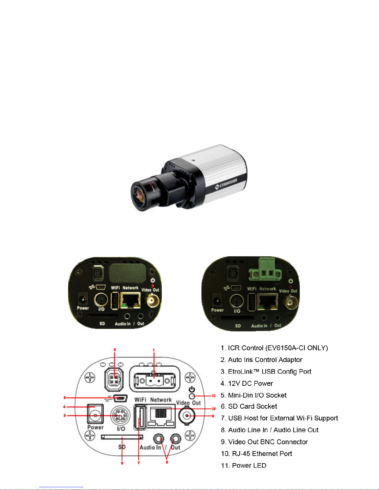
l Front
l Rear
l Connectors
EV6150A-B
EV6150A-CI
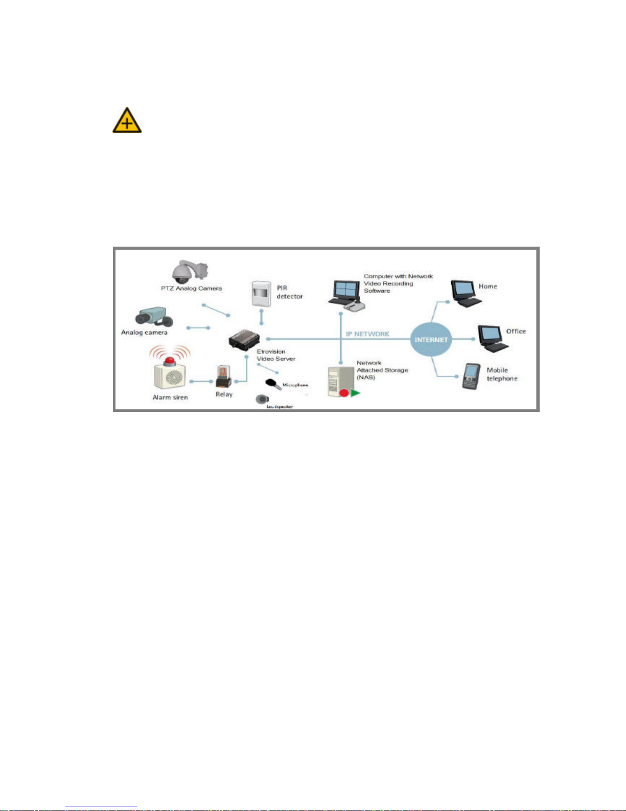
2. SETTING AND INSTALLATION
Note:
l Connect EV6150A- BI / EV6150A-CI to your network by using a standard Cat-5
cable.
l Connect the video output of your camera with video in of video server, using
standard 75O coaxial cable with BNC type connector.
l Connect speaker and active microphone to Audio In / Out.
l Product CD
Product CD in th e package contains:
ü EtroStation™ 3.0 NVR management software
o 16CH Live View / Recording / 4CH Playback
ü EtroStation™ Pro 3.0 NVR management software
o 36CH Live View/Recording/4CH Playback
ü User’s Manual
l Power on IP Camera
Use the power adapter, provided in the package, to power on the IP
camera. The adapter should be connected to 110v~22Ov AC socket.

l Connect to Network
Connect EV6150A-BI / EV6150A-CI and network hub/switch via a
standard CAT5 Ethernet cable and RJ-45 socket. Please pay attention that
the PC must be on the same network domain with the IP camera.
l Connect I/O
Users have to make pin-to-pin correctly to enable this function.
l Enable Audio Function
n The video flicker may occur when enabling or disenabling audio
in and audio ou t. The situation normally lasts for a second.
3. USING EV6150A-BI / EV6 150A-CI FOR THE
FIRST TIME
l Before You Install Software
ü Please check PC OS platform. Microsoft Windows 2000 or
Windows XP is capable of running EtroStation™ 3.0 software.
ü PLEASE read EtroStation™ 3.0 user’s manual before installation .
l Language Support
ü English

l Install EtroStation™ 3.0
User can easily find the specific IP camera on the network via this
software.
l Browser for Live Viewing and Video Settings
Microsoft IE browser version 6 or higher is recommended. Currently
Mozilla Firefox and others are not compatible.
l Factory Setting – Initial IP Address
Default IP Address: 192.168.1.2
Gateway: 192.168.1.1
Subnet Mask: 255.255.255.0
l Network Domain
Alter the IP address of the PC to the same domain of default value
(192.168.1.2). Users may alter the IP address of the IP camera to the
same of PC via EtroScan™ . Please refer to page 45 to check detailed
information.
l Use EtroScan™
The software allows users easily and quickl y find the specific IP camera on
the network. Run EtroStation™ 3.0 setup and install the two applications.
The following is the brief instruction:
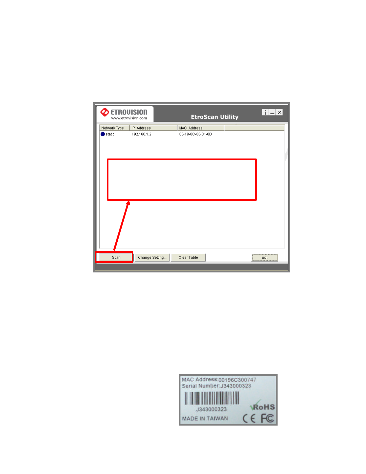
Select EtroScan™ from the start menu. User can see the following image:
Press Scan button to check the IP and MAC address list. Press Clear
Table button and press Scan again to refresh.
You will find the list of IP and MAC address listed. To indentify your IP
camera you can flip over the IP camera and check the label for MAC
address on the bottom side.
Press Scan to automatically find online IP Camera
on the
network domain
Note: Please pay attention that a completed RMA form must contain the serial
number of the product. For more information, please refer to our
website.
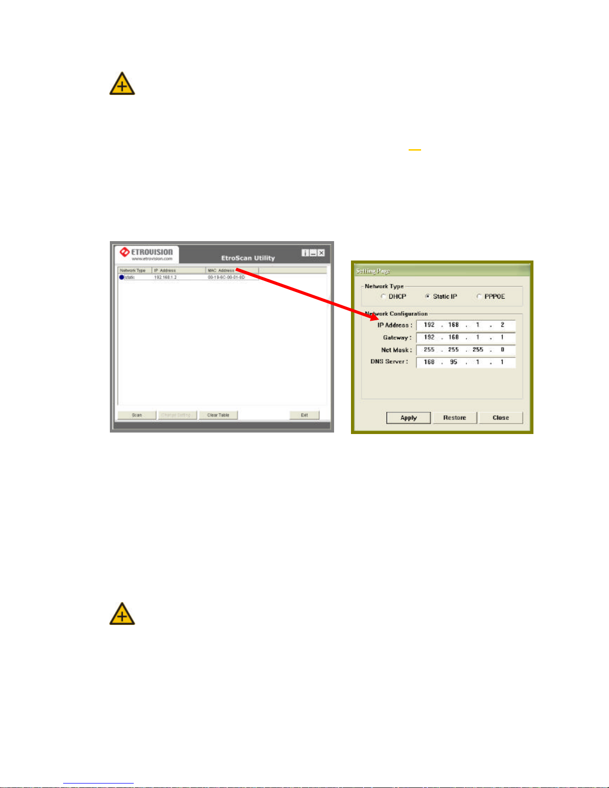
l Change Network Setting via EtroScan™
Double click on a specific IP address; the setting page will pop up. Users
may alter some basic network parameters in this page.
Be sure to press APPLY to enable the new setting
Within 10 seconds, the dialog box would disappear. This indicates that the
new settings are deployed. After typing in the new IP address, user may
close the setting page and wait for 45 seconds. It takes 45 seconds to
restart the system. After rebooting, user may press Scan to check the
new IP address.
Note: “DOUBLE Right Click Function” à Double right click on a specific IP
address on the list; user can quickly open the live viewing browser
page.
Press Exit to quit.
Double click
4. ACCESS IP CAMERA
l Browser
Ø Open an IE browser
Ø Type in the IP address of video server that you found via EtroSacn™ . For
example: 192.168.1.2 (default IP address)
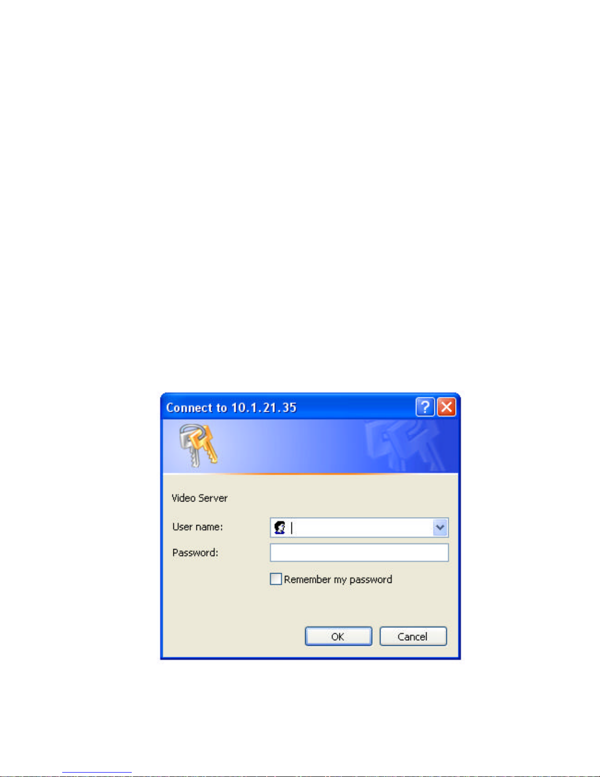
Ø A popup login dialog box will automatically display.
Ø Initial username and password (case-sensitive):
Login: root
Password: pass
Press OK button to access to the live viewing web page.
l Initial Username & Password
root
pass
à Administrator
Ø Default ID / Password = root / pass
Ø The ID of administrator can not be changed or deleted; only the
password is changeable.
Ø Administrator has the authority to view and control system settings.
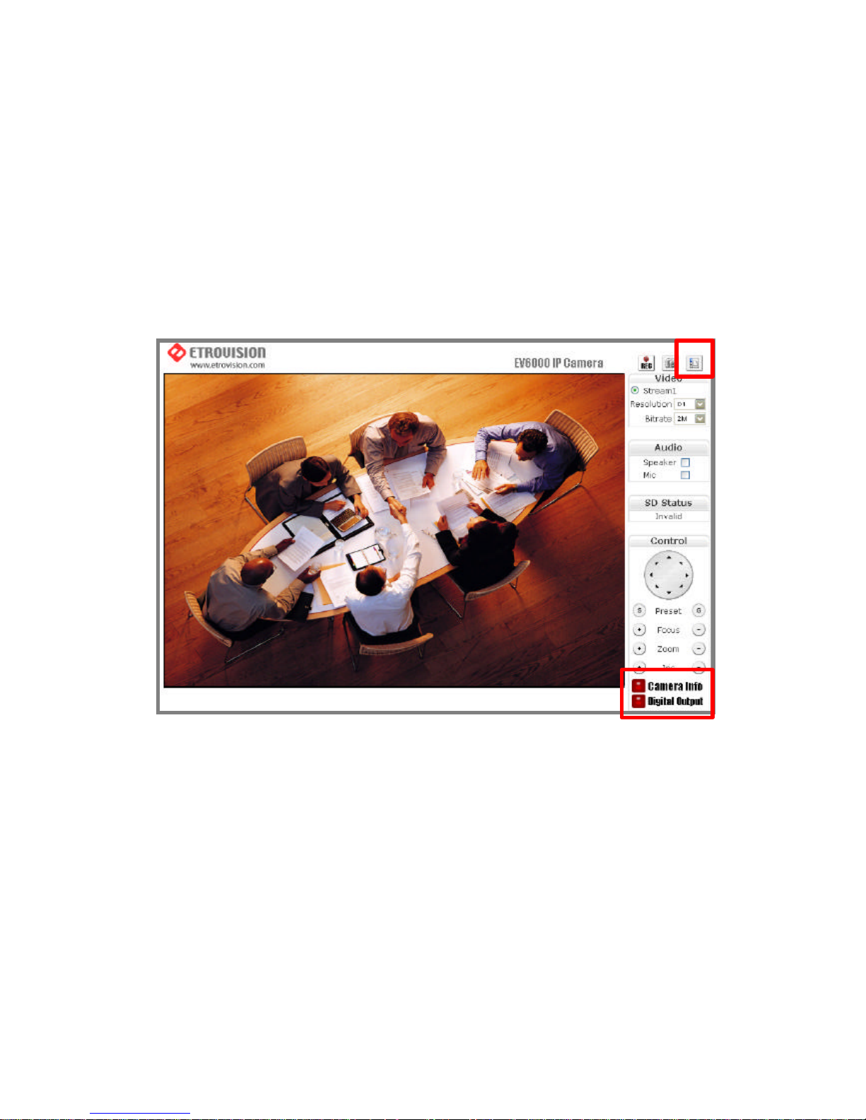
After logging in with root / pass as administrator, user may see the live
viewing page.
1. There is a toggle button on the top right corner of the live viewing
page.
2. User may press this button to switch web configuration page to the
live viewing page and vice versa.
3. Control options are listed on the right side.
4. OSD is displayed on top left corner of the screen .
The sequence is date (mm-dd-yyyy), time, and camera name.

(camera name is selectively displayed)
l Control Panel Settings
1. Video / Resolution
The following table shows common resolution format values:
2. Video rates / Bit rates
3. Choose a specific value and the setting will be enable d within few
seconds. The image on the screen might briefly pause.
4. Camera information (Please refer to the picture)
The button is on the lower right corner of the living viewing image,
showing video information such as frame rate (fps), model name,
Resolution CIF QCIF D1
NTSC
352X240 176X120 720X480
PAL
352X288 176X144 720X576
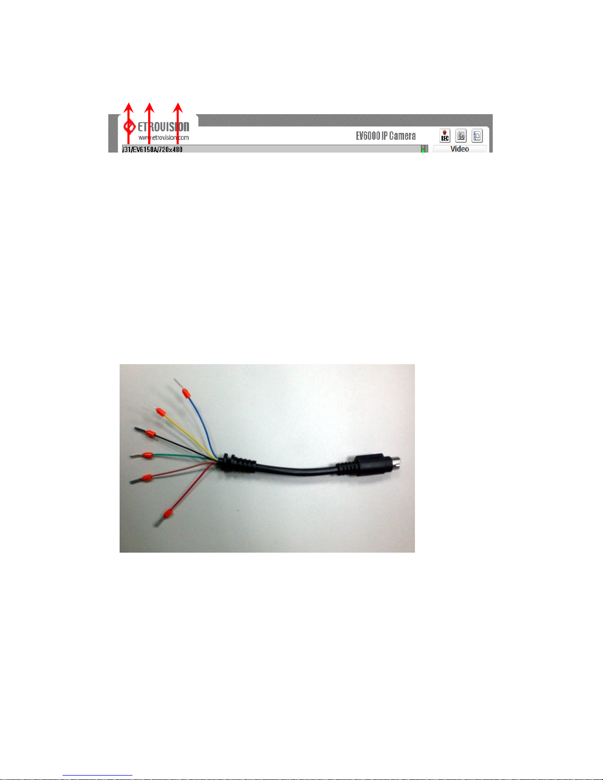
and resolution.
5. Digital Output (Please refer to the picture)
To enable this function, user has to connect the PIN via the Mini DIN
cable. The toggle button works as a switch to enable/disenable
Digital Out function.
l Pin Define
- Blue line : RS485 +
- Yellow line : DI +
- Black line : DI -
- Green line : RS485 -
- Brown line : DO +
- Red line : DO –
FPS Name Resolution
5. WEB INTERFACE SETTINGS – BASIC
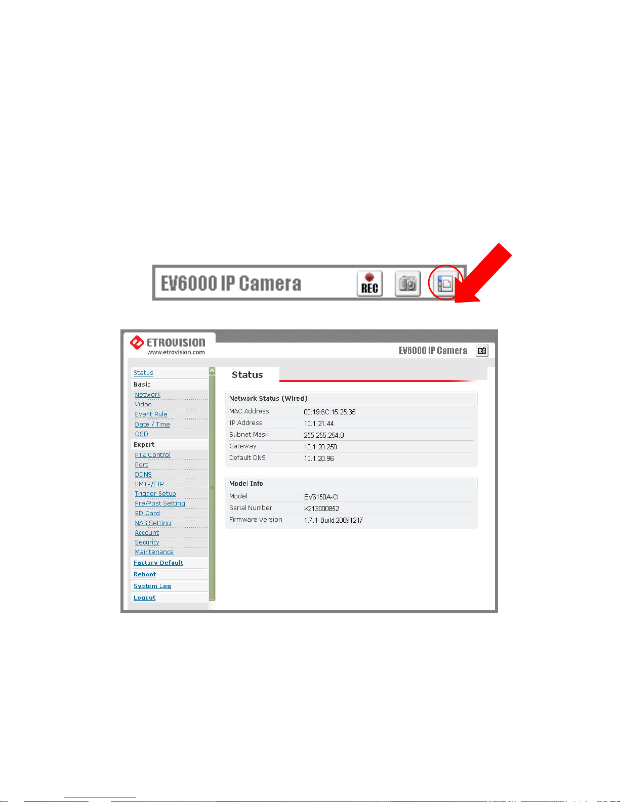
EV6150A-BI / EV6150A-CI built-in web interface provides the access to
further settings. Enable the top -right side icon in the live viewing page
to access to the further settings. This button also works as a switch
between configuration and live viewing page.
l Status
1. Status is the first item of the setting options.
2. This page shows the IP address, MAC address of the video server,
hardware, firmware information , and other related information.
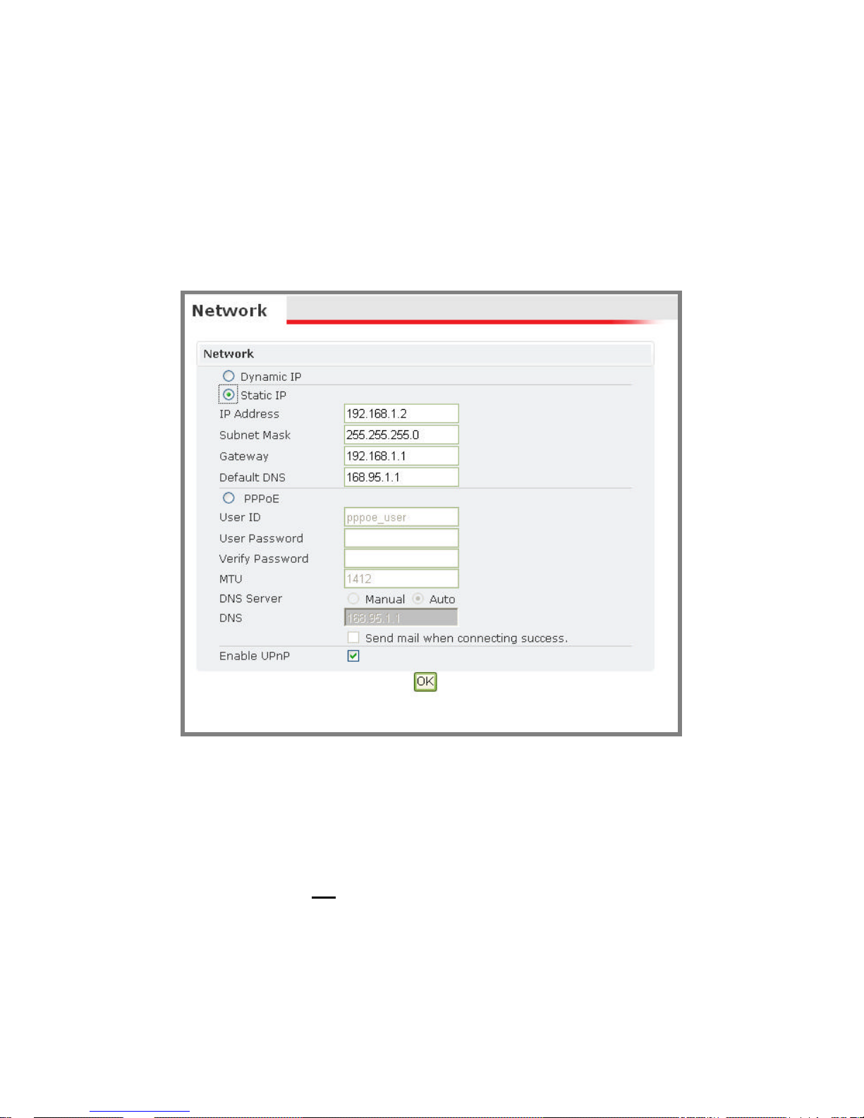
l Network
There are three available types of wired network connection: STATIC,
DYNAMIC and, PPPoE.
à Static IP
1. IP Address
Please confirm with the network administrator.
2. Subnet Mask / Gateway / Default DNS
Please confirm with the network administrator.
3. Be sure to press “OK” to save the new setting.
4. Reboot will be required and automatically triggered after pressing OK.
Please wait for a moment to the count down timer stop. The page will be
redirected to the initial login one.
Note: Always use Etro Scan™ to find the MAC addresses after reboot and
double check the IP address. Make sure the IP address is correct. If IP
was changed in web configuration, you cannot return to initial login
page after reboot.
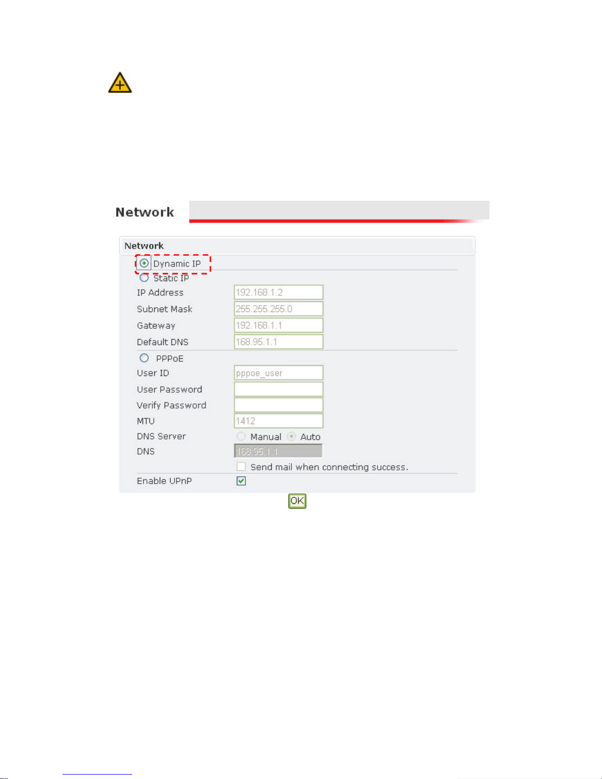
à Dynamic IP
1. If DHCP server is on LAN and you want to allocate Dynamic IP address,
use DHCP.
2. Press “OK” button.
3. Reboot will be required and automatically triggered after pressing OK.
4. Please wait for a moment to the count down timer stop. The page will be
redirected to the initial login one.
Note: Always use Etro Scan™ to find the MAC addresses after reboot and
double check the IP address. Make sure the IP address is correct. If IP
was changed in web configuration, you cannot return to initial login
page after reboot.
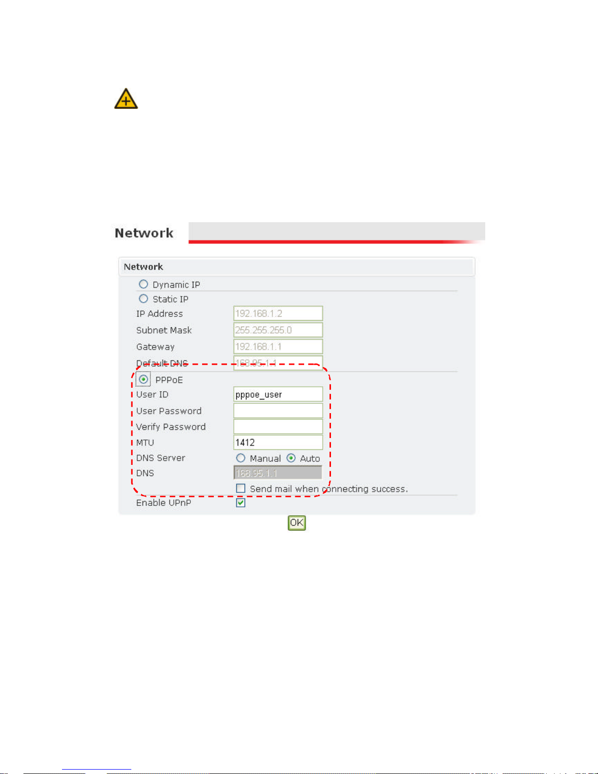
à PPPoE Settings
1. If the network supports PPPoE like xDSL, this option is available.
2. Require ISP (Internet Service Provider) to provide ID/Password.
3. User ID / Password
4. PPPoE user ID / Password
5. Service Name: Service name of ISP
6. MTU
。Maximum transmission unit of data
7. IP address of DNS sever can be set to be automatically created.
8. If xDSL does not use static IP, you should use DHCP.
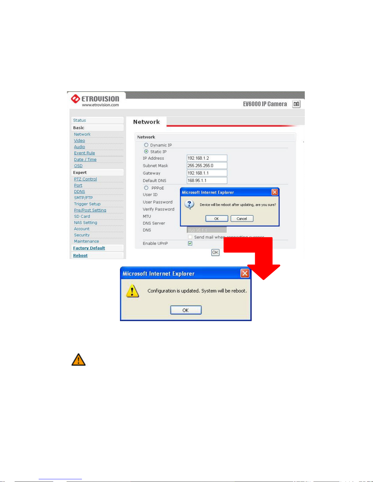
Caution: Be sure press “OK” after you have changed the setting in a
particular setting page. After few seconds, a confirmation dialog
box will pop up to indicate that the setting has been updated. To
return to the same page, please press “OK ”.
l Video
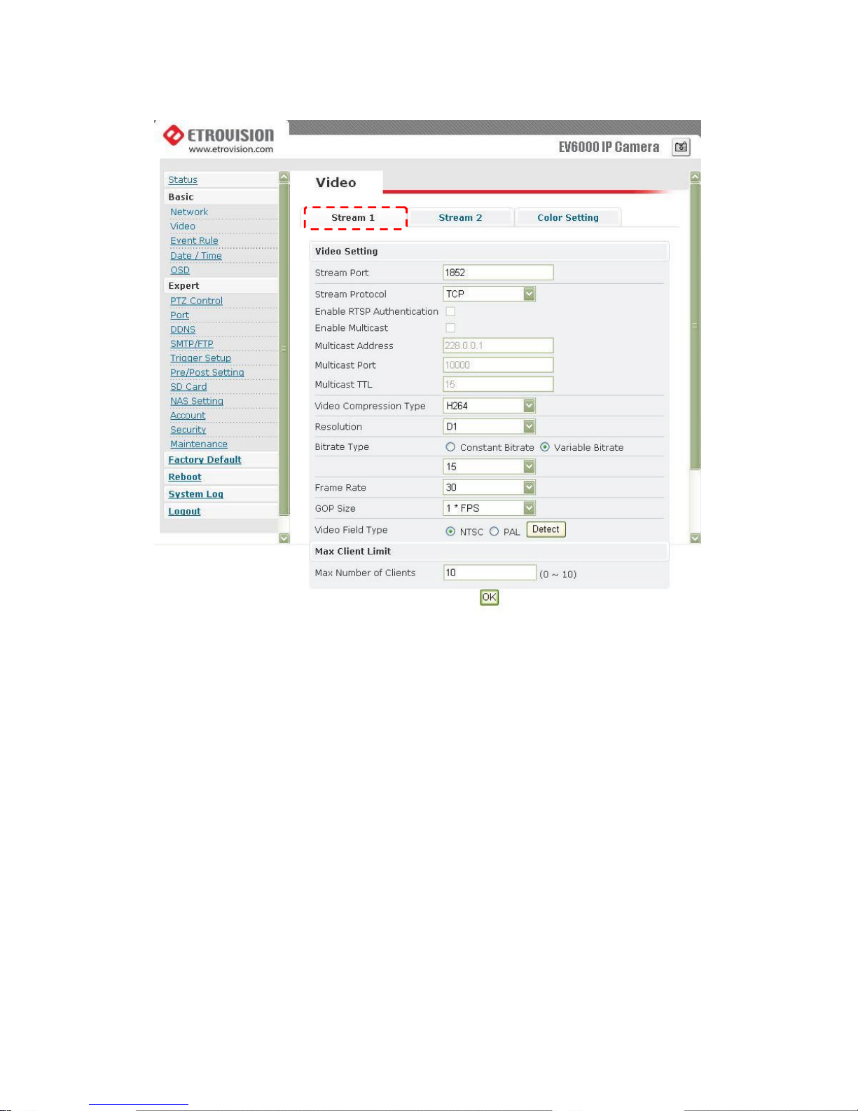
Stream 1
à Video Settings
1. Stream Port: Stream 1 port value setting
2. Stream Protocol: Selectable options: TCP/UDP (RTP) / User can decide
whether to enable multicast function or not (If UDP is selected).
3. Video Compression Type: Selectable options : H264/M-JEPG / MPEG-4
4. Resolution : Selectable Options: D1/CIF/QCIF
5. Bit rate Type: There are two selectable options: constant bit rates (CBR)
and variable bit rates (VBR), providing the flexibility in choosing
bandwidth .
6. Constant bit rates (CBR): 4M / 3M / 2M / 1.5M / 1M / 750K / 500K / 384K
/ 256K / 128K / 64K

Note: 1M is recommended when using H.264; 1.5M is recommended when
using MPEG-4.
Note: When mosaic or fragment occurs in the image, users may lower the
frame rate or assign another level of image quality.
7. Variable bit rates (VBR) ranges: 15 ~ 51 (The value “15” is default.)
8. Frame per second: 1 / 5 / 10 / 15 / 20 / 25 / 30
9. Group Size (GOP): This function is designed for adjusting the ratio
between “I” frame and “P” frame. Lower the group size represents the
lower bandwidth consumption.
10.Video Type: NTSC / PAL
Note: System can automatically detect the input video signal when the
detect icon clicked.
à Max Client
This function allows more than one user to have the access to the video
stream. The relationship between bit rates, resolution, and the client
amount is an inverse ratio.
Maximum number of clients depends on the available network bandwidth
and the required video quality. The available range is 0 ~ 10.
Stream 2
Caution: You have to enable Stream 2 in this section to see the option on the
 Loading...