

EtroVISION 1080p/5M series User Manual

USERS
MANUAL
EV8x8x Models
Firmware Version 1.2.0
Document Revision A
ETROVISION TECHNOLOGY / www.etrovision.com / +886-2-2655-1518 / Technical Support: etrotech@etrovision.com / Sales Contact: etrosales@etrovision.com

-
- IP Setting
-
SETTINGS
CONTENT
1. INTRODUCTION 4
2. THE LIVE VIEW 5
Live View, Setup & Client Setup 6
Client Setup 7
- Recording Path
- Streaming Protocol
- Buffering Time
Controls and Status 8
- Speed Dome Models
Digital Zoom 8
Information 10
Streaming 10
Audio 10
N53 Panorama Mode 11
Control (PTZ Control) 11
- Speed Dome PTZ Control
- N53 Digital PTZ Control
- EV8x8xQ-MD
12
12
13
3. SETUP 14
System – Information 15
System – Generic Setting 16
- Camera Name
- System Time
- Schedule Reboot
- Camera Lens (for EV8180 models
16
16
16
17
only)
- Digital Input
- LED
- HTTP Port
- Language
17
17
18
18
System – User Account Management 18
System – Maintenance 19
Firmware Update
- Web UI Firmware Upgrade
- Upgrade using SD Card
- Clean the ActiveX and IE Cache &
19
19
20
20
History
- Export/Import Camera
23
Configuration
- Restore Factory Default
- Reboot Device
23
23
System – Local Storage 24
System – Recording/Snapshot 25
- Event-Triggered Recording
- Continuous Recording
- Snapshot Setting
7
7
7
Cyclic Recording 26
System – ONVIF 26
Network – IP Setting 27
25
25
26
27
8
- WLAN Setting
27
Network – Streaming 29
Network – DDNS 30
Network – Access Filtering 30
Network – IP Probe 31
Network – Quality of Service 31
Network – SNMP 32
Video/Audio – Video Setting 33
- TV Output
- Resolution Mode
33
34
(EV8x80F Models Only)
- Profile Setting
34
Video/Audio – Audio Setting 36
Video/Audio – Color Setting 36
- Day/Night Setting
- IR-Cut Filter
- Color & Sensor Settings
36
36
37
Video/Audio – Text Overlay 39
Video/Audio – Privacy Mask 39
Event Handle – Event Rule 41
- EV8280 Event Actions
42
Event Handle – Event Server 42
- Email Setting
- Network Storage
- FTP Server
TCP/HTTP Recipient
42
43
43
44
Event Handle – Motion Detection 45
PTZ Control – Serial Setting 46
System Log – View Log 47
System Log – Remote Log Setting 47
4. PTZ DOME CAMERA CONTROL
48
PTZ Control – General Setting 48
- Home Function
48
Content 2

5. MOTION JPEG IN A BROWSER
PTZ Control – Patrol 49
PTZ Control – Auto Scan 51
PTZ Control – Privacy Mask 53
55
6. STREAMING VIDEO 56
RTSP Streaming 56
- Authentication
Image Snapshot in a Browser 57
7. ROUTER/FIREWALL CONFIGURATION 58
Streaming Router Configuration 58
- Camera Router/Firewall
- Clients only requiring streaming via
HTTP
- Clients only streaming RTP over
RTSP/TCP
- Clients only streaming using RTP
over UDP
- Client Router/Firewall
- DMZ
- Open UDP Port
- Firewall/Security Settings
57
58
58
58
59
60
60
61
61
8. ADDING A CAMERA TO AN NVR 62
RTSP URL 62
Administrator User & Password 63
9. FIREFOX 64
10. DIGITAL INPUT/OUTPUT 65
Digital Input 65
Digital Output 65
11. DOCUMENT CHANGE LOG 66
Document Version 66
Content 3

1 INTRODUCTION
This guide is for the use with the 1080p/5MP series using firmware version 1.1.5.003.
The User’s Manual provides functionality and instructions for the 1080p/5M series which includes the
EV1180 megapixel model series (EV8x8x cameras).
Before Using the IP Camera/Video Server
- Check the PC requirements
- Review the OS platform requirements
- Read an special and import precautionary information
- Having basic knowledge of network setup and configuration will be helpful
Disclaimer
© 2012 Etrovision Technology. All rights reserved.
EtroLink™ & AnyUSB™ are trademarks of Etrovision Technology; other product or service names mentioned
herein are the trademarks of their respective owners. Information contained in this document may be
superseded by updates. No representation or warranty is given and no liability is assumed by Etrovision
Technology with respect to the accuracy or use of the information, or infringement of patents or other
intellectual property rights. No licenses are conveyed, implicitly or otherwise, under any intellectual
property rights.
1 Introduction 4

2 THE LIVE VIEW
The IP camera web interface is made up of two main pages: the Live View page and the Setup page. The
Live View provides the current display from the IP camera along with selected settings, configuration and
functionality.
A login is required to access the web UI. The administrator username is “root”, and the password by default
is “pass”.
After logging into the IP camera via the browser, the user is first presented with the Live View interface.
Below is an example of the Live View page. Following the screenshot is a discussion of the different areas
within the Live View page.
2 The live view 5
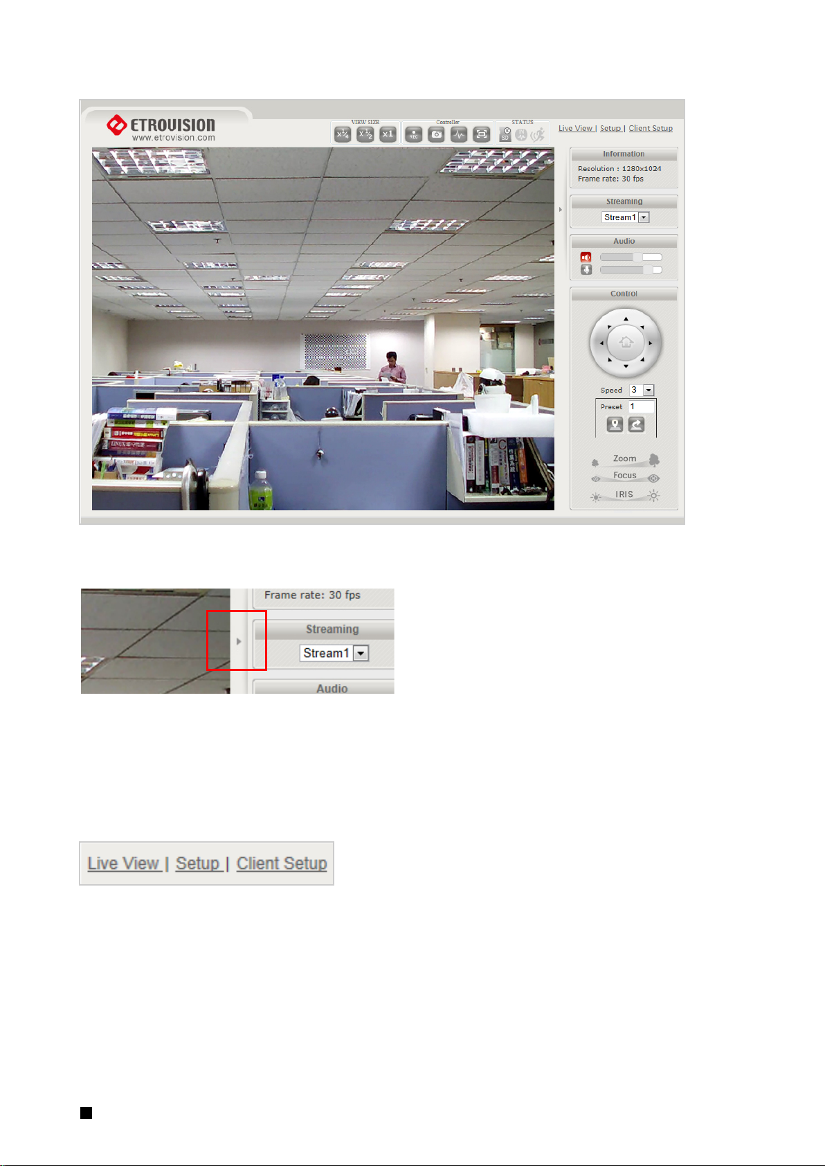
The right hand panel (Information, Streaming, Audio, Control) can be hidden by clicking the small arrow
bordering the video and Streaming panel.
Click the arrow (highlighted in red) to hide/display the right side panel.
Live View, Setup & Client Setup
In the top right corner of the screen are three links.
Live View: the main viewing screen with various controls.
Setup: provides the interface for most of the camera configuration.
Client Setup: configuration for PC client settings such as storage directory, and web UI streaming
preferences.
2 The live view 6
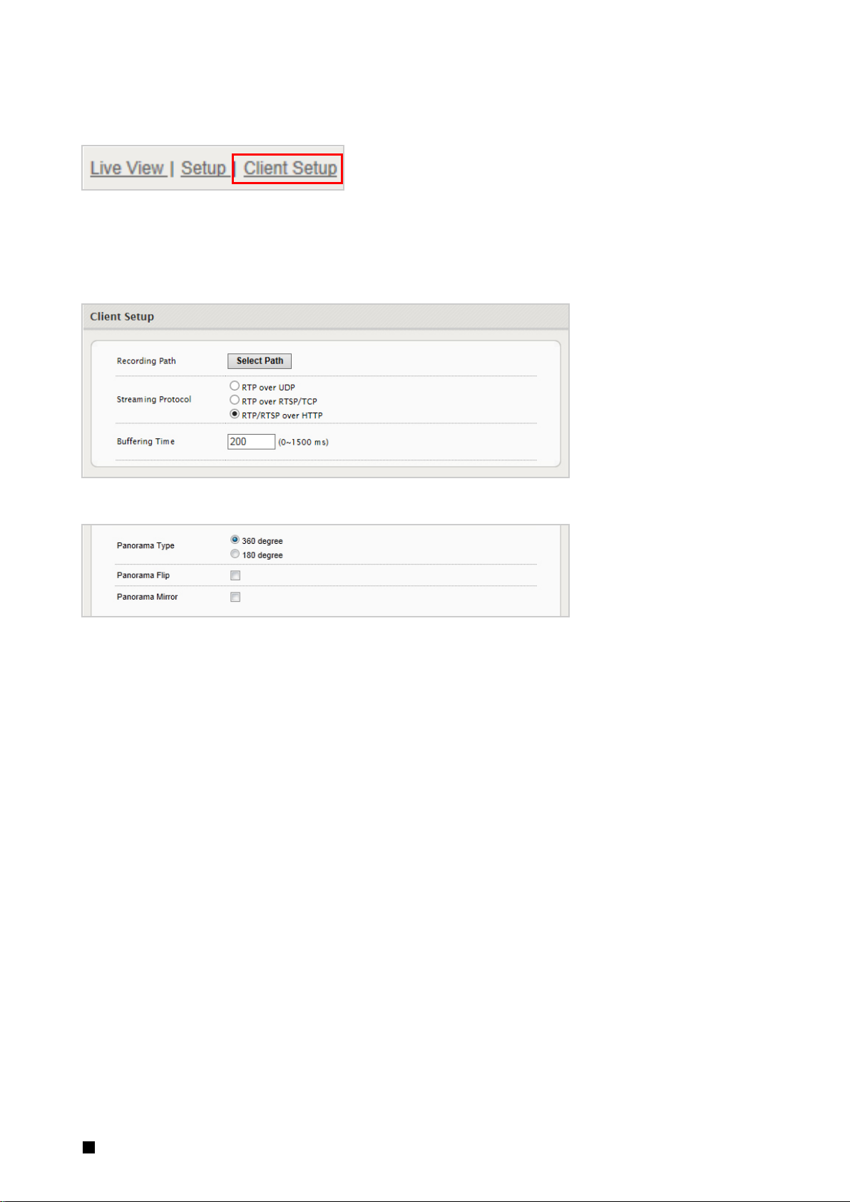
Client Setup
The Client Setup provides options to modify the recording path, streaming protocol and buffering time.
Streaming protocol and buffering time relate to streaming settings for the web UI on the client PC. These
settings are only applied for the browser session, and don’t persist after the browser is closed.
Settings apply to a specific PC; they are not universal.
The N53 model also includes some additional client setup parameters specific to that model.
Recording Path
Recording Path is used to define the directory where snapshot images and video will be stored.
Streaming Protocol
RTP/RTSP over HTTP is the default. This is the most flexible setting in that it streams using port 80
which should likely require no client router configuration.
RTP over UDP may use less bandwidth than the other options, but it may also result in inferior video
quality since packets may be lost in transmission (more common over WAN) and may require
additional router client configuration for UDP traffic.
See section 5 Router/Firewall Configuration for more information on network configuration
considerations.
Buffering Time
Buffering Time can be increased if video appears to lag due to network latency. However, an
increased buffer will result in increased lag between real time.
2 The live view 7
Record
2. Digital
Out
4. SD
Card
6. Motion
Alert
1. Adjust
Live View
3. Full
5. Digital In
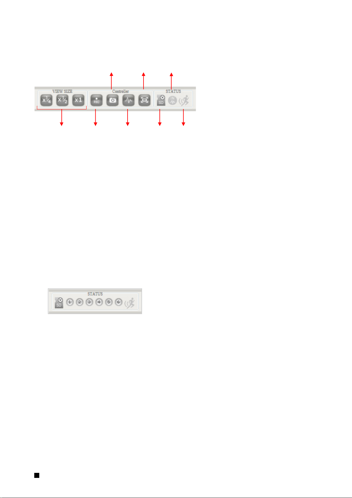
Controls and Status
SnapShot
Screen
Alert
Detection
1. The View Size controls adjust the viewable screen size in Live View. The Zoom feature can be used,
and Record and Snapshot will capture video/snapshots to the local hard drive.
2. Digital Out will trigger a digital output signal (e.g. to an alarm).
3. Full Screen will display video in full screen mode. Click the Esc key to exit Full Screen mode.
4. SD Card shows the status of the SD card.
5. Digital In Alert will display when a digital in alert has been triggered.
6. Motion Detection Alert will display when motion detection has been triggered.
Speed Dome Models
The speed dome cameras hav 6 digital input connections. Therefore, the Live View Digital IN alert
displays 6 separate signals labeled 1-6.
2 The live view 8
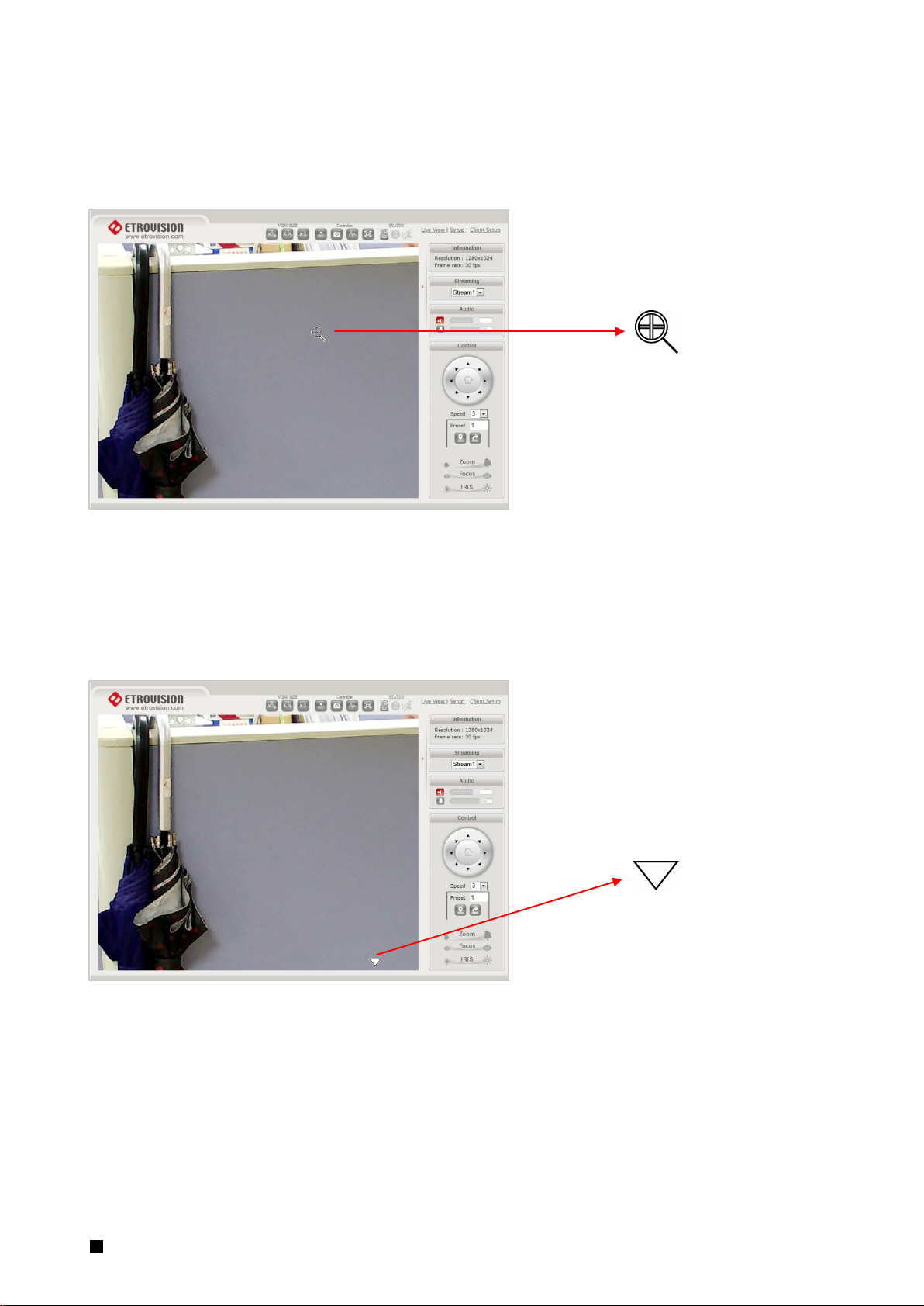
Digital Zoom
The Digital Zoom feature allows zooming in on a specific area. When using the View Size controls, a
magnifying glass icon will replace the mouse pointer icon.
To magnify a specific area, place the magnifying glass icon over the desired area and left click the mouse.
Additional left mouse clicks will continue to magnify wherever the mouse is placed.
To zoom out, right click the mouse.
If the mouse is moved to the edge of the image window, the mouse icon will change to a white, triangular
icon.
This icon allows moving the view using electronic PTZ if the functionality is available and enabled.
2 The live view 9

Information
Resolution and frame rate will be displayed in the Information pane.
Streaming
To toggle between different video streams, use the Stream drop down list.
The number of ROI which are enabled in the Video Setting – Profile Setting will determine the number of
streams available for viewing. See the “Video Control – Video Setting” section for more information.
Audio
Audio volume controls for speaker and microphone. Clicking on the icon will mute or enable.
2 The live view 10
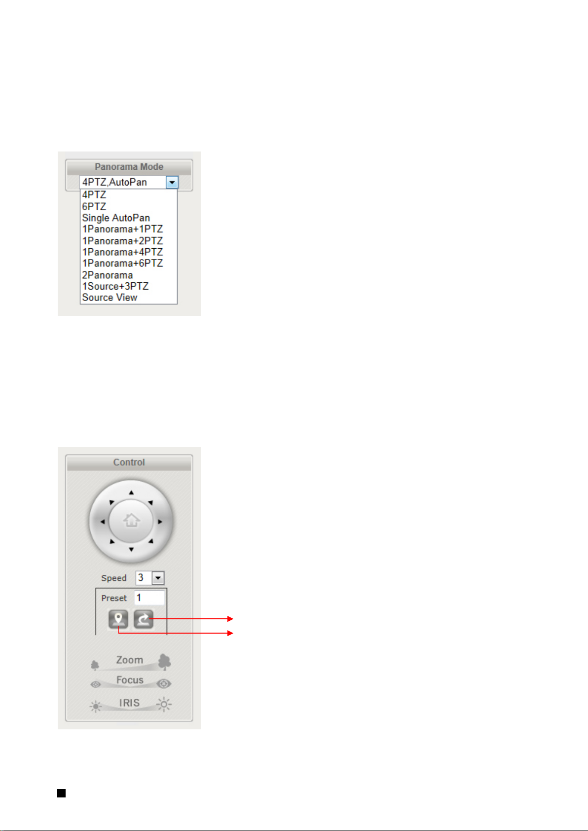
N53 Panorama Mode
The N53 fisheye model has some additional options for displaying video in the Live View. The N53’s wide
panoramic view allows for displaying the image in multiple ways.
The display options differ between the F and U models.
The positioning of the views cannot be permanently set to display in a specific position when the Live View
is opened.
Control (PTZ Control)
The PTZ control panel will not be present in those models where PTZ will not be used (e.g. EV8580). Use the
Set Preset button to mark a preset, and the Go to Preset button to use a preset.
Go to Preset
Set Preset
2 The live view 11

Speed Dome PTZ Control
The speed dome cameras have some additional PTZ controls displayed in the Control panel. For more
information about the speed dome PTZ functionality, see the section PTZ Dome Camera PTZ Control
Settings.
Home
Go to Preset
Set Preset
Auto Focus
Auto Scan
Auto Patrol
Disabled if AF enabled
N53 Digital PTZ Control
The N53 can display multiple views, so select the desired Window to use the PTZ.
2 The live view 12
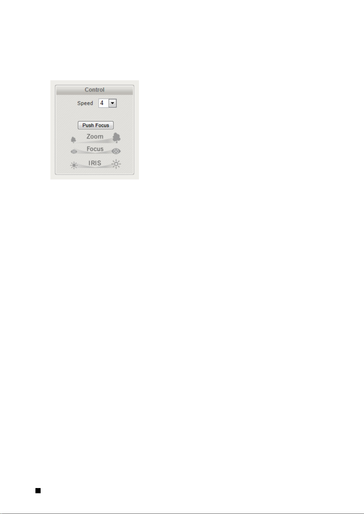
EV8x8xQ-MD
The EV8x8xQ-MD models (Computar Zoom Lens) also have a Push Focus function which automatically
determines the optimal focus for a given setting.
2 The live view 13
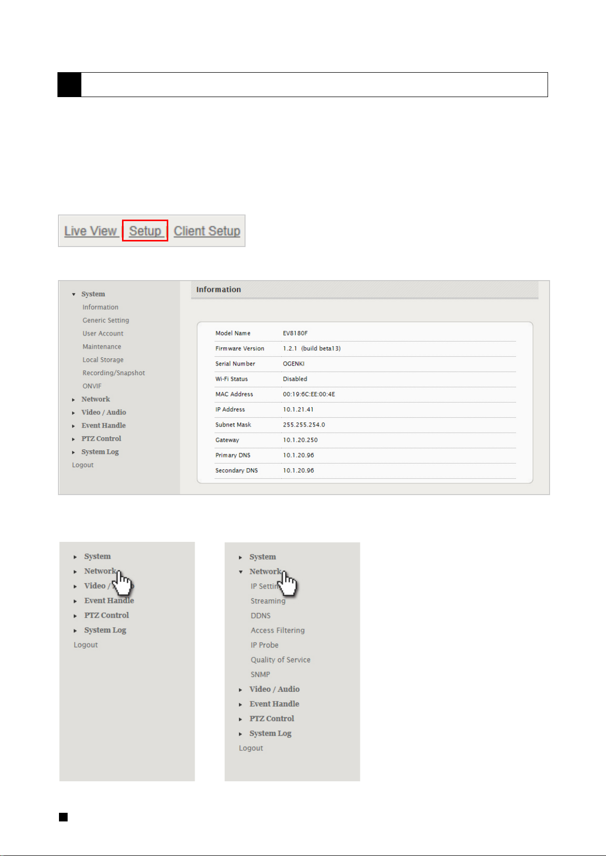
3 SETUP
The web interface is made up of two main pages: the Live View page and the Setup page. The Live View
page interface was introduced in the previous section.
The Setup interface is primarily used for viewing and configuring the IP camera’s settings.
From the Live View page, click the Setup link at the top right side:
Below is a screenshot of the Setup page. The initial page displayed is the “System Information” page.
The left hand panel lists the configuration nodes which can be viewed and modified. Clicking on an item will
reveal sub menus which are available.
3 Setup 14

To return to the Live View page, click the Live View link in the right hand corner.
NOTE: Configuration changes in the Setup interface require clicking the SAVE button. Otherwise, changes
will not be applied.
The following discusses the different basic configuration options within the Settings page.
System – Information
The Information page is always the initial page displayed when switching to the Setup view. Basic
information related to the IP camera is displayed here.
The page only displays information; no changes can be made here.
3 Setup 15
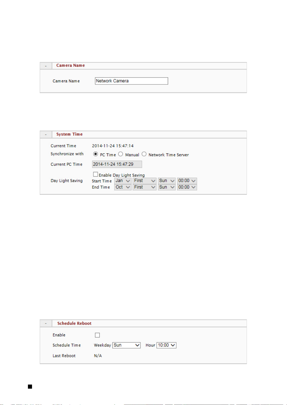
System – Generic Setting
Camera Name
Enter a camera name if a specific name is desired.
System Time
3 options are available:
- Manual: insert time manually
- PC Time: set to the current PC time
- Network Time Server: periodically synchronizes with a time server
For Network Time Server two standard options are provided. If another time server is preferred, then
choose others from the list and add the address of the time server which will be used.
Renew Period specifies the synchronization schedule.
Day Light Saving allows the daylight saving time to be defined. When the Enable Day Light Saving is
checked, the start and end time should be configured to define the DST start/end time. The camera
will then automatically adjust for DST.
Schedule Reboot
3 Setup 16
The camera can be configured to reboot on a weekly basis if desired. Last Reboot displays the date
and time of the last reboot.
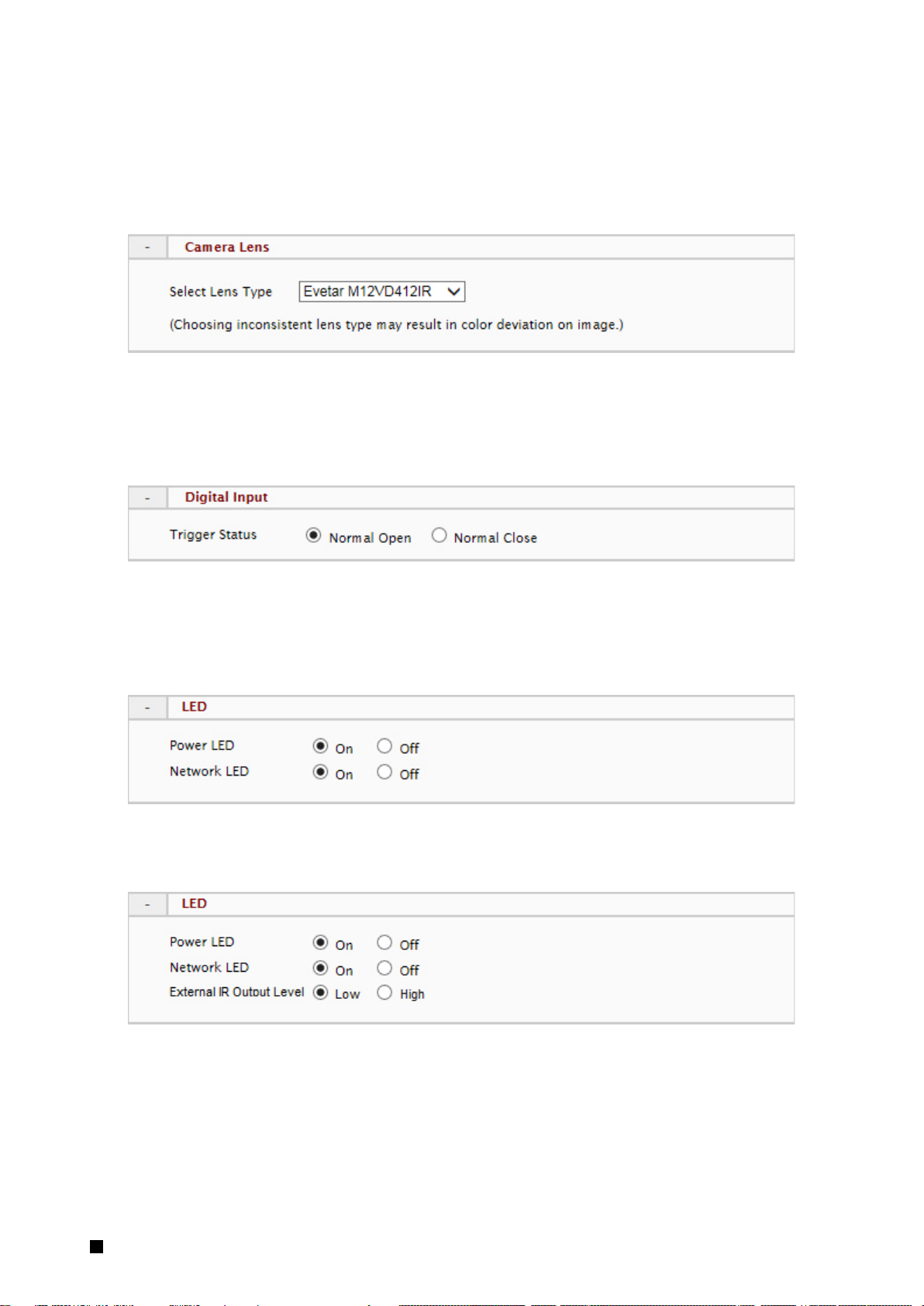
Camera Lens (for EV8180 models only)
Select the appropriate lens type for the camera. A mismatch between the Camera Lens setting and
the actual lens type may result in color deviation.
Digital Input
This defines the method by which the digital in sensor operates. If the normal condition is open (N.O.),
then the alarm will be triggered when the circuit is closed. The opposite applies for N.C.
LED
The camera LED lights can be enabled or disabled.
The EV8781 has an additional setting which controls operation of an external IR LED source.
The External IR Output Level controls the circuit voltage which is used to turn on/off the external IR
LED.
NOTE: Refer to the external IR LED manufacturer’s recommendation to properly set the External IR
Output Level.
Low = Active Low: no voltage turns on the external IR LED; voltage turns off the IR LED
3 Setup 17
High = Active High: voltage turns on the external IR LED; no voltage turns off the IR LED
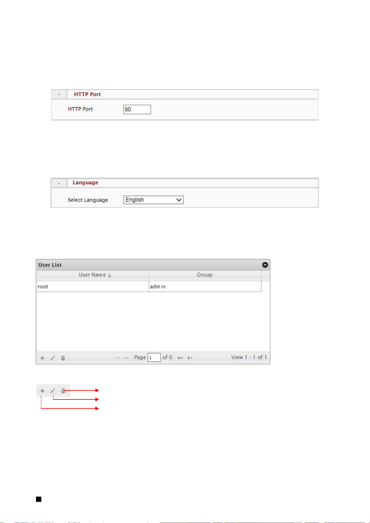
HTTP Port
To use a non-default port, change the HTTP Port value. This port is used by the camera’s web server
and HTTP streaming.
Language
Currently English, Simplified Chinese, Czech, French, German, Russian and Italian are available.
System – User Account Management
User accounts can be added, edited or deleted via the controls in the left corner.
Delete User
Edit User
Add User
3 Setup 18
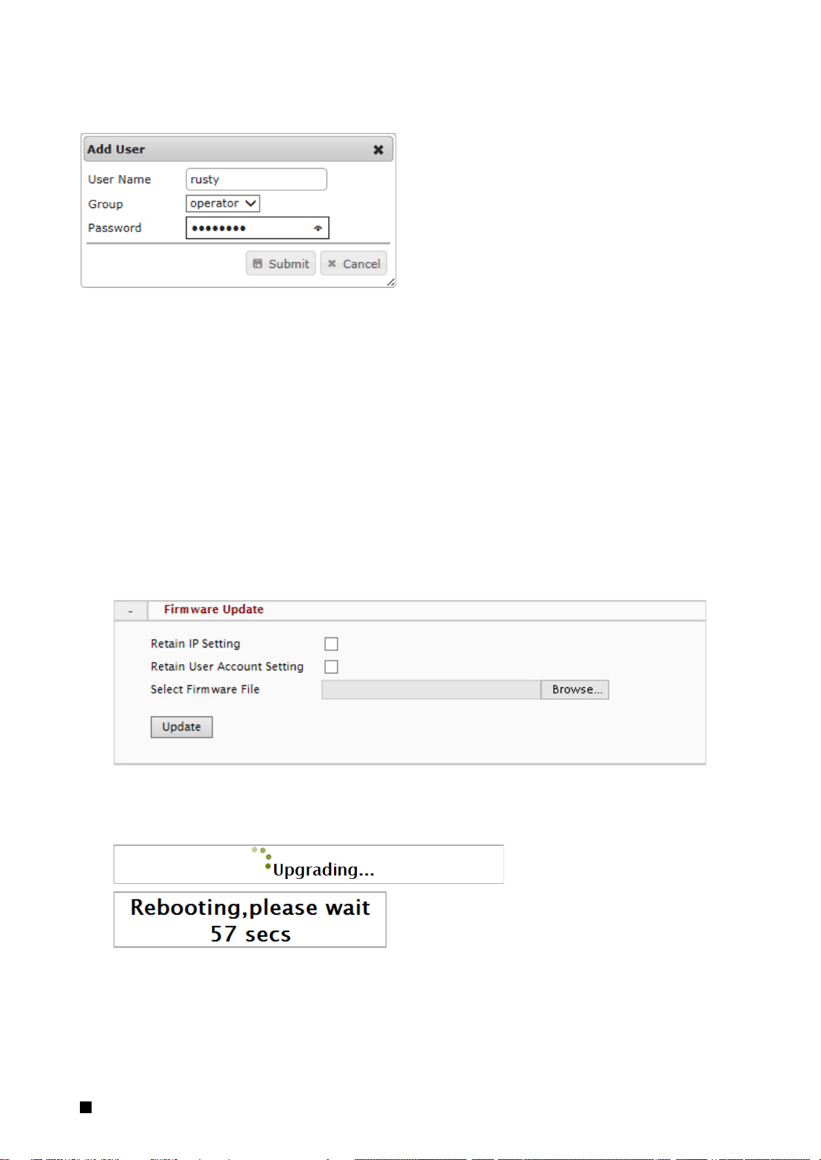
Users are assigned to a group (admin, operator or viewer).
To edit or delete an account, highlight the account in the User List window and click the edit/delete button.
After making changes, click SAVE to apply changes.
System – Maintenance
Firmware Update
The firmware can be upgraded using the web UI or an SD card. After upgrading, the ActiveX controls
and browser cache should be cleaned to prevent old controls & pages from being used.
Web UI Firmware Upgrade
IP and User Account settings can be preserved by checking the appropriate boxes. After selecting the
new firmware file, click Update to proceed. Messages that the camera is upgrading and rebooting will
follow during the upgrade.
Perform the steps in “Clean the ActiveX and IE Cache & History” below, using Etroscan change the
network settings (if applicable), then check the System Information page to verify the upgrade has
been completed successfully.
3 Setup 19
Upgrade using SD Card
The SD card should be empty of any existing files before proceeding.
1. Rename the firmware file to ev-fw.bin, and copy the file to the SD card.
2. Insert the card into the camera’s SD card slot.
3. Power on the camera, and wait about 1 minute.
The green power LED will flash quickly during the upgrade, become stable briefly and slowly blink
while performing a reboot.
4. Check EtroScan to verify the camera is available (IP address may have changed to factory default,
192.168.1.2).
5. Remove the SD card.
6. After web UI access is once again available, review the System Information page to verify the
upgrade has completed successfully.
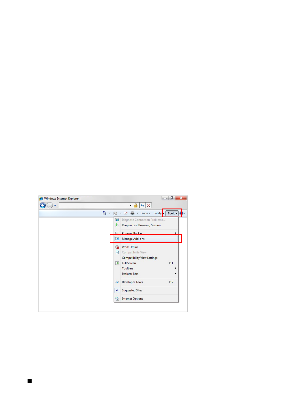
Clean the ActiveX and IE Cache & History
After upgrading, the ActiveX controls and IE cache & history should be cleared to prevent old pages
and controls from being used.
Close all instances of IE and open 1 IE window. In the right corner, select Tools->Manage Add-ons
3 Setup 20
 Loading...